Language selection

Search

Patent 2432994 Summary

Third-party information liability

Some of the information on this Web page has been provided by external sources. The Government of Canada is not responsible for the accuracy, reliability or currency of the information supplied by external sources. Users wishing to rely upon this information should consult directly with the source of the information. Content provided by external sources is not subject to official languages, privacy and accessibility requirements.

Claims and Abstract availability

Any discrepancies in the text and image of the Claims and Abstract are due to differing posting times. Text of the Claims and Abstract are posted:

  • At the time the application is open to public inspection;
  • At the time of issue of the patent (grant).
(12) Patent Application: (11) CA 2432994
(54) English Title: FLAIL MALLET ASSEMBLY
(54) French Title: SYSTEME DE MAILLET A FLEAU
Status: Deemed Abandoned and Beyond the Period of Reinstatement - Pending Response to Notice of Disregarded Communication
Bibliographic Data
(51) International Patent Classification (IPC):
  • B02C 13/28 (2006.01)
  • B02C 18/18 (2006.01)
(72) Inventors :
  • DOPPSTADT, WERNER (Germany)
(73) Owners :
  • WERNER DOPPSTADT UMWELTTECHNIK GMBH & CO KG
(71) Applicants :
  • WERNER DOPPSTADT UMWELTTECHNIK GMBH & CO KG (Germany)
(74) Agent: RICHES, MCKENZIE & HERBERT LLP
(74) Associate agent:
(45) Issued:
(86) PCT Filing Date: 2002-01-08
(87) Open to Public Inspection: 2002-07-18
Examination requested: 2006-08-23
Availability of licence: N/A
Dedicated to the Public: N/A
(25) Language of filing: English

Patent Cooperation Treaty (PCT): Yes
(86) PCT Filing Number: PCT/EP2002/000100
(87) International Publication Number: EP2002000100
(85) National Entry: 2003-06-23

(30) Application Priority Data:
Application No. Country/Territory Date
101 01 434.1 (Germany) 2001-01-13

Abstracts

English Abstract


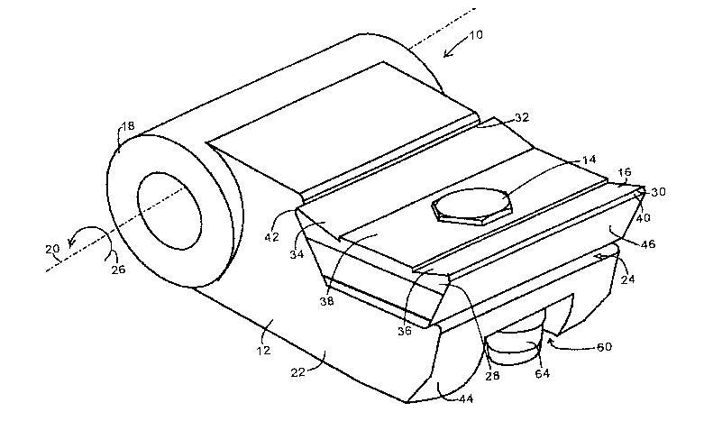
The invention relates to a beating arrangement for a rotary shredder,
comprising a base body (12) which is rotationally arranged around an axis (20)
and a cutting body (16) which is detachably fixed onto a protruding part (22)
of the base body. A protruding profile (50) is formed on the front surface
thereof in the direction of rotation whereon the cutting body (16) forms a
positive fit. The profile (50) can be embodied in the form of a protruding
truncated pyramid, whose base surface lies on the plane of the front surface
(24) of the protruding parts. The cutting body (16) can comprise two cutting
edges (30, 32) which are bilaterally symmetrical in relation to a surface
which extends tangentially in relation to a circumference of rotation. The
cutting body can be fixed by means of a screw (14), which extends through the
centre of the cutting body and the profile.


French Abstract

L'invention concerne un système de fléau pour un déchiqueteur à rotor, qui comprend un corps de base (12) logé rotatif autour d'un axe (20) et un corps de coupe (16) fixé détachable sur une partie en saillie (22) du corps de base. Sur la surface avant dans le sens de rotation de la partie en saillie (22) est formé un profil saillant (50) sur lequel le corps de coupe (16) s'applique par liaison de forme. Le profil (50) peut avoir la forme d'une pyramide tronquée saillante dont la surface de base se trouve dans le plan de la surface avant (24) de la partie en saillie. Le corps de coupe (16) peut présenter deux arêtes coupantes (30, 32) en symétrie bilatérale par rapport à une surface tangentielle à une circonférence de rotation. Le corps de coupe peut être fixé au moyen d'une vis (14) qui traverse centralement le corps de coupe et le profil.

Claims

Note: Claims are shown in the official language in which they were submitted.


7
Claims
1. Swinging flail mallet for rotor shredders, comprising
(a) a base body (12) having a pivot bearing (18), by means of which the flail
mallet (10) is mounted on a rotor for rotation about a pivot axis parallel to
the rotor axis, and having a surface at the front, with respect to the
direction
of rotation, extending over the total width of the base body (12) and forming
a step and a plane surface (34) contiguous therewith , which defines a
reduced-thickness plate-like end portion (22) of the base body (12),
(b) a cutting body (16), which also extends across the total width of the base
body (12) and has a base, defining a plane base surface (26) and having
wedge-shaped cutting ledges of triangular cross section projecting at the two
ends thereof and having cutting edges (30,32) parallel to the pivot axis, and
(c) means for attaching the cutting body (16) to the base body (12) such that
the
plane base surface (26) lies on the plane surface (34) of the step,
characterized in that
(d) the cutting edges have plane outer surfaces extending at an angle
outwards,
contiguous to the base surface (26) of the base,

8
(e) an outer one of the cutting edges projecting at an angle outwards beyond
the
plane base surface of the base project, with their cutting edge (30), beyond
the
outer end of the base body (12) remote from the pivot axis,
(f) a projection (50) is formed on the plane surface (24), the cutting body
(16)
being placed thereon with a complementary recess in its base surface (26) of
the cutting body (26),
(g) the cutting body (16), with the outer surface of its inner cutting edge
and its
base surface (26) , lies form-fittingly on the step of the base body (16),
whereby the cutting body (16) is closely engaged, on two sides, by the base
body.
2. Flail mallet assembly according to claim 1, characterized in that the
profile has
the form of a projecting truncated pyramid, its base area laying in the plane
of the
front surface of the projection.
3. Flail mallet assembly according to claim 1 or 2, characterized in that the
cutting
body is provided with two cutting edges symmetrical to a plane extending
tangential to a rotational circumference.
4. Flail mallet assembly according to one of the preceeding claims,
characterized in
that the cutting body is screwed by means of a screw extending through the
middle
of the cutting body and through the profile.
5. Flail mallet assembly according to claim 4, characterized in that the base
body
has a recess at the in the direction of the rear surface, with respect to the
rotation, of
the projection, wherein a nut for the screw can be embedded.
6. Flail mallet assembly according to claim 4, characterized in that the
cutting body
is provided with a recess at the in the direction of the front surface, with
respect to
the rotation, wherein the head of the screw can be embedded.

9
7. Flail mallet assembly according to one of the proceeding claims,
characterized in
that the surface of the cutting body is chamfered at the side opposite to the
axis of
rotation and is aligned with the chamfered side of the base body opposite to
the axis
of rotation, when the cutting body is fixed to the base body.
8. Flail mallet assembly according to one of the proceeding claims,
characterized in
that the cutting edge of the cutting body is hardened.

Description

Note: Descriptions are shown in the official language in which they were submitted.


CA 02432994 2003-06-23
Flail mallet assembly
Technical Field
The invention relates to a flail mallet assembly for rotor shredders with a
base body
rotatably mounted about an axis and a cutting body releaseably fixed to a
projection of
the base body. Such flail mallets are used as striking tools for rotor
shredders for, for
example, plastic, wood or the like.
State of the Art
From the DE 35 45 708 C2 a flail mallet assembly is known, wherein a cutting
body
shaped as a tooth is releaseably fixed with its shaft in a recess. The fixing
is carried out
by means of a screw extending through a bore hole in the base body and the
shaft of the
cutting body. The shaft is provided with a projecting edge at its end
extending around a
projection in the recess. Furthermore the shaft has a profile projecting into
a
complementary profile within the recess. Thereby the tooth is kept in its
position even
when strong forces occur. Usually the tip of the flail mallet is worn such
that an edge is
formed along the rotating movement direction of the flail mallet. Due to the
complex
shape of the described flail mallet assembly its production is difficult and
expensive.
From the DE-OS 29 43 456 a device for shreddering of bark and annual plants is
known.
The device comprises a rotating body with a flail mallet arranged close to its
circumference. Each flail mallet consists of a base body on one end pivotably
arranged at
the rotating body and of a cutting body fixed at the front surface, with
respect to rotation,
of the flail mallet. These cutting bodies are exchangeably fixed to the
respective flail
mallet bodies, as they suffer quick wear during operation of the assembly and
can
therefore be replaced without having to exchange the entire flail mallet.

CA 02432994 2003-06-23
2
With both arrangements comparatively much material, i.e. the entire cutting
body, is
rendered useless if the tip of the flail mallet is exchanged.
Disclosure of the invention
It is the object of the invention to provide a flail mallet assembly with an
easily
replaceable cutting body using as little material as possible. It is a further
object of the
invention to provide a flail mallet assembly which can easily produced. It is
yet another
object of the invention to provide a flail mallet assembly with a good
transmission of
forces to the base body.
According to the invention these objects are achieved by a flail mallet
assembly
according to the first portion of claim 1, the flail mallet assembly being
provided with a
projecting profile at the in the direction of the rotation front surface of
the projection, to
which the cutting body is form-fitted. Thereby an optimal transmission of the
forces is
achieved by Form-fitting. The material which shall be cut usually generate
great forces in
different directions of the cutting body and through the cutting body to the
base body of
the flail mallet assembly. By transmitting the forces by form-fitting, not
only forces
perpendicular to the direction of movement of the cutting body can be taken
up, but also
all other active forces of the cutting material to the flail mallet. No
extensive strain on
fixing devices, such as by screws and the like occurs.
The profile at the base body corresponds to the profile at the cutting body,
for example a
recess. Thereby the cutting body has a smaller volume with the respective
smaller
material consumption.
In a preferred embodiment of the invention the profile has the form of a
projecting
truncated pyramid, its base area laying in the plane of the front surface of
the projection.
This Form is easy to manufacture and suitably reduces the material
consumption. With the
amount of sides of the truncated pyramid the amount of positions is set, in
which the

CA 02432994 2003-06-23
3
cutting body can be fixed. Thereby an adjusting position of the cutting edge
is not
necessary.
Preferably the cutting body is provided with two cutting edges symmetrical two
a plane
running tangential to a rotational circumference. However, there can be a
plurality of
cutting edges, also. For a four-sided truncated pyramid four cutting edges are
possible. If
the truncated pyramid has more sides the amount of cutting edges can be
increased. In
this embodiment the cutting body can be used several times. The cutting body
only has to
be loosened and turned by an angle set by the geometry and fixed again.
Thereby the
material consumption and the required time are further reduced.
In a further embodiment of the invention the cutting body is screwed by means
of a screw
running through the middle of the cutting body and through the profile. There
are further
ways of fixing, especially because the side forces are not taken up by the
screw anymore
but by the profile. The base body preferably has a recess at the in the
direction of the
rotation rear surface of the projection, wherein the nut for the screw can be
embedded.
Thereby the strain and damaging of the nut is avoided. Furhtermore the
required length of
the screw is shortened. Furthermore the cutting body can be provided with a
recess at the
in the direction of the rotation Front surface, wherein the head of the screw
can be
embedded at least partially. Thereby less strain and damaging of the head of
the screw is
effected.
In order to achieve an optimal cutting effect with small damaging and wear of
the base
body the surface of the cutting body preferably being chamfered at the side
opposite to
the axis of rotation. This one is aligned with the chamfered side of the base
body opposite
to the axis of rotation, when the cutting body is fixed to the base body.
Thereby the wear
of the base body is minimized.
The cutting edge of the cutting body preferably is hardened to ensure a long
lifetime.
Further embodiments of the invention are subject matter of the subclaims. An
example is
described below in greater detail with reference to the accompanying drawings.

CA 02432994 2003-06-23
4
Brief description of the drawings
Fig.l shows a perspective view of a rotor flail mallet with a base body and a
cutting
body screwed onto it.
Fig.2 shows a perspective view of the rotor flail mallet of Fig. l without the
cutting
body.
Fig.3 shows a cut view through the rotor flail mallet of Fig.l .
Description of an embodiment
In Fig.l, 10 denotes a rotor flail mallet. The rotor flail mallet 10 comprises
a base body
12 and a cutting body 16 screwed onto it with a screw 14, which forms the tip
of the flail
mallet. The base body 12 consists of a hollow cylinder 18 being rotatably
mounted about
an axis 20. A projection 22 is provided at the hollow cylinder. The projection
22 is
shaped essentially with a step, wherein the "step" has a surface 24 on which
the cutting
bodv 16 lies. The surface 24 is directed in the direction of the rotational
movement
represented by an arrow 26 in Fig.1. It, therefore, forms the front surface of
the base body
12. The cutting body 16 lies in a fitted manner on the base body 12. Due to
the step-like
arrangement the cutting body 16 is surrounded on two sides by the base body 12
and
forms a unit therewith, where cutting material cannot enter into.
The cutting body 16 has a uniform trapezoid cross section over its entire
width. The
smaller parallel surface 26 of the trapezoid forms the rear side of the
cutting body 16
adjacent to the front surface 24 of the base body 12. The front portion 28 of
the cutting
body 16 is hardened. Thereby the wear of the cutting edges is delayed. The
cutting body
can also consist of two portions, a hardened front portion and a non-hardened
back
portion being connected with each other.

CA 02432994 2003-06-23
The front portion 28 of the cutting body comprises two cutting edges 30 and
32, parallel
to each other on opposite sides of the cutting body. In different embodiments
four cutting
edges can be provided on each side of the cutting body at an angle of about 90
degrees.
The cutting edges 30 and 32 are slightly projecting. Accordingly the surface
34 or 36,
5 respectively runs a little inclined towards the edges. Thereby an optimal
cutting effect is
achieved. In order to achieve a good stability the middle portion 38 of the
front surface
between the cutting edges 30 and 32 is straight, i.e. parallel with respect to
the rear
surface 26 of the cutting body. The angle of the cross-sectional trapezoid is
truncated
somewhat at its ends 40 and 42. This is shown in Fig. 3 also.
The rear surface of the base body 12 and the surface 44 opposite to the axis
are not
exactly plane. Thereby the resistance with respect to the cutting material is
smaller. The
surface 44 opposite to the axis extends such that it joins the side surface 46
of the cutting
body 16 without edges.
In Fig.2 the base body 12 is shown without the cutting body. At the front
surface 24 of
the base body 12 a profile 50 in the form of a truncated pyramid can be seen.
Within the
truncated pyramid 50 a bore hole 52 is provided for the screw 14. The sides 54
have a
relative angle of 90 degrees and two sides have edges parallel to the cutting
angles 30, 32
(Fig.3).
The cutting body 16 has a recess on its back side which is complementary to
the profile
50. By this arrangement the cutting body 16 can only be screwed on or
otherwise fixed in
tour different positions on the base body. An adjustment is not necessary. In
the present
case the cutting body 16 is fixed in such a way that the two cutting edges 30,
32 extend
parallel to the axis 20 of rotation of the flail mallet. 1f the cutting edge
used up the screw
14 is loosende, the cutting body is rotated by an angle of 180 degrees and the
screw is
fixed again. The "fresh" cutting edge then sits at the position of the
previous one. If
cutting edges are provided at each side of the cutting body 16 the cutting
body can be
used four times instead of two times. If further cutting edges shall be
provided the
amount of sides of the truncated pyramid 50 has to be increased.

CA 02432994 2003-06-23
6
A recess 60 is provided on the rear side of the base body 12 . The screw 14
extends
through a bore hole 62 in the cutting body 16 and the bore hole 52 in the base
body. A
fitting nut 64 for the screw 14 is arranged in the recess 60. Thereby the bore
holes 52 and
62 do not need to be threaded which of course is also possible. Due to the
protected
position of the head of the screw and the nut they are not or only little
affected by the
cutting material.

Representative Drawing
A single figure which represents the drawing illustrating the invention.
Administrative Status

2024-08-01:As part of the Next Generation Patents (NGP) transition, the Canadian Patents Database (CPD) now contains a more detailed Event History, which replicates the Event Log of our new back-office solution.

Please note that "Inactive:" events refers to events no longer in use in our new back-office solution.

For a clearer understanding of the status of the application/patent presented on this page, the site Disclaimer , as well as the definitions for Patent , Event History , Maintenance Fee  and Payment History  should be consulted.

Event History

Description Date
Time Limit for Reversal Expired 2008-01-08
Application Not Reinstated by Deadline 2008-01-08
Deemed Abandoned - Failure to Respond to Maintenance Fee Notice 2007-01-08
Letter Sent 2006-09-18
Request for Examination Received 2006-08-23
Request for Examination Requirements Determined Compliant 2006-08-23
All Requirements for Examination Determined Compliant 2006-08-23
Letter Sent 2004-01-30
Inactive: Single transfer 2003-12-24
Inactive: IPRP received 2003-10-24
Inactive: Courtesy letter - Evidence 2003-09-30
Inactive: Cover page published 2003-09-26
Inactive: Notice - National entry - No RFE 2003-09-23
Application Received - PCT 2003-07-29
National Entry Requirements Determined Compliant 2003-06-23
Application Published (Open to Public Inspection) 2002-07-18

Abandonment History

Abandonment Date Reason Reinstatement Date
2007-01-08

Maintenance Fee

The last payment was received on 2006-01-03

Note : If the full payment has not been received on or before the date indicated, a further fee may be required which may be one of the following

  • the reinstatement fee;
  • the late payment fee; or
  • additional fee to reverse deemed expiry.

Patent fees are adjusted on the 1st of January every year. The amounts above are the current amounts if received by December 31 of the current year.
Please refer to the CIPO Patent Fees web page to see all current fee amounts.

Fee History

Fee Type Anniversary Year Due Date Paid Date
Registration of a document 2003-06-23
MF (application, 2nd anniv.) - standard 02 2004-01-08 2003-06-23
Basic national fee - standard 2003-06-23
MF (application, 3rd anniv.) - standard 03 2005-01-10 2004-12-16
MF (application, 4th anniv.) - standard 04 2006-01-09 2006-01-03
Request for examination - standard 2006-08-23
Owners on Record

Note: Records showing the ownership history in alphabetical order.

Current Owners on Record
WERNER DOPPSTADT UMWELTTECHNIK GMBH & CO KG
Past Owners on Record
WERNER DOPPSTADT
Past Owners that do not appear in the "Owners on Record" listing will appear in other documentation within the application.
Documents

To view selected files, please enter reCAPTCHA code :


To view images, click a link in the Document Description column. To download the documents, select one or more checkboxes in the first column and then click the "Download Selected in PDF format (Zip Archive)" or the "Download Selected as Single PDF" button.

List of published and non-published patent-specific documents on the CPD .

If you have any difficulty accessing content, you can call the Client Service Centre at 1-866-997-1936 or send them an e-mail at CIPO Client Service Centre.


Document
Description 
Date
(yyyy-mm-dd) 
Number of pages   Size of Image (KB) 
Abstract 2003-06-22 2 86
Description 2003-06-22 6 246
Representative drawing 2003-06-22 1 31
Claims 2003-06-22 3 81
Drawings 2003-06-22 3 50
Notice of National Entry 2003-09-22 1 188
Courtesy - Certificate of registration (related document(s)) 2004-01-29 1 107
Reminder - Request for Examination 2006-09-10 1 116
Acknowledgement of Request for Examination 2006-09-17 1 176
Courtesy - Abandonment Letter (Maintenance Fee) 2007-03-04 1 175
PCT 2003-06-22 8 286
Correspondence 2003-09-22 1 25
PCT 2003-06-23 4 167
Fees 2004-12-15 1 33
Fees 2006-01-02 1 34