Note: Descriptions are shown in the official language in which they were submitted.
CA 02433493 2003-06-30
WO 02/056035 PCT/US01/49039
LOW COST, ON-LINE CORROSION
MONITOR AND SMART CORROSION PROBE
BACKGROUND OF THE INVENTION
The present invention generally relates to a device,
method and system for industrial processing. More
specifically, the present invention relates to a device,
method and system for monitoring corrosive industrial
processes.
It is, of course, generally known that various
industrial processes produce corrosive by-products. Such
corrosive by-products frequently corrode industrial
equipment, increase production costs, and create
production delays. Thus, corrosion monitoring is a
valuable tool which can alleviate such process upsets.
At present, typically on-line corrosion monitoring
equipment for industrial processing is relatively
expensive and cumbersome to use. Such corrosion
monitoring devices frequently contain large and
complicated monitoring components which are not portable
and must be placed in a permanent fixed position in
relation to the industrial process being monitored.
Moreover, because such equipment is large, complicated
and cumbersome, it may be difficult to set up and operate
in an efficient manner by either skilled or unskilled
personnel.
It is generally known that currently available
corrosion monitoring devices are capable of storing data
for later downloading to other computerized devices.
However, such corrosion devices often lack the ability to
provide real-time corrosion monitoring or the capability
CA 02433493 2003-06-30
WO 02/056035 PCT/US01/49039
2
to communicate with more portable computerized devices
such as laptop or handheld computers.
Another problem sometimes encountered with currently
available corrosion monitoring devices is that such
devices are not disposable. Although some corrosion
monitoring devices offer replaceable components, many
function improperly and are often very expensive.
The disposability problem can be further
exacerbated because many currently available monitoring
devices do not offer waterproof or weatherproof
enclosures. Thus, moisture and exposure to other
environmental elements harms many of the internal
components of such devices. Thus, the life span,
functional consistency and monitoring reliability of at
least some currently available corrosion monitoring
devices can be significantly reduced. Such detrimental
environmental effects can also significantly increase the
operation and maintenance costs of those devices as well.
A still further problem encountered with at least
some prior art corrosion monitoring devices is the
substantial number of inaccurate readings. In most
instances, the inaccuracy occurs because the monitoring
device is incapable of identifying the type of
metallurgical material utilized by the device to
determine corrosion rate.
For example, within most corrosion monitoring
devices, an electrode probe having a specific metallurgy
is used to determine corrosion rate of an industrial
process. The corrosion rate is determined based upon the
corrosivity of the industrial process upon the specific
type of metallic probe electrode used. If the metallurgy
CA 02433493 2003-06-30
WO 02/056035 PCT/US01/49039
3
of the probe changes or cannot be determined by the
monitoring device, frequent and substantial inaccurate
readings result which must later be accounted for and
corrected. To correct such misreadings, additional
operating costs are incurred.
Improved device, method and system for monitoring
industrial processes would therefore be desirable.
SUMMARY OF THE INVENTION
The present invention relates to an improved device,
method and system for monitoring an industrial process.
More specifically, the present invention relates to an
improved device, method and system for monitoring
industrial corrosive cooling water treatment processes.
To this end, the present invention provides a device
comprising a controller module; a probe module which
operably communicates with the controller module; and a
resistor module which operably communicates with the
controller module, wherein the resistor module is capable
of identifying the probe module to the controller module.
The present invention also provides a corrosion
monitoring system comprising a controller module; a probe
module having at least one metallurgical probe electrode
which operably communicates with the controller module;
and a resistor module having a resistance value which
operably communicates with the controller module, wherein
the resistance value identifies the metallurgy of the
probe electrode to the controller module.
Additionally, the present invention also provides a
method of determining corrosion rate comprising the steps
of providing a corrosion monitoring device comprising a
controller module; a probe module which operably
CA 02433493 2003-06-30
WO 02/056035 PCT/US01/49039
4
communicates with the controller module; and a resistor
module which operably communicates with the controller
module; placing the probe module within a solution;
charging the probe module and resistor module with a
current via the controller module; identifying the type
of probe module by the controller module based upon the
resistance value of the charged resistor module; and
determining the rate of corrosion by the controller
module after the probe module has been identified.
Moreover, the present invention further provides a
probe device comprising an electrode and a resistor
having a resistance value which identifies the electrode.
Additional features and advantages of the present
invention are described in and will be apparent from, the
detailed description of the presently preferred
embodiments and from the drawings.
BRIEF DESCRIPTION OF THE FIGURES
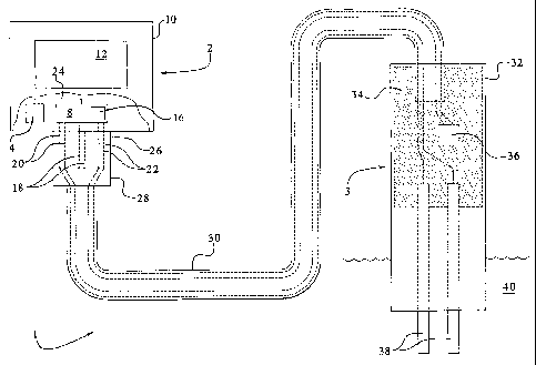
Fig. 1 illustrates a perspective view of an
embodiment of the device of the present invention.
DETAILED DESCRIPTION OF THE PRESENTLY PREFERRED
EMBODIMENTS
The present invention relates to devices, methods
and systems for monitoring corrosive industrial
processes. More specifically, the present invention
relates to devices, methods and systems for monitoring
corrosion of industrial cooling water treatment systems.
Referring now to the drawings wherein like numerals
refer to like parts, Fig. 1 illustrates an embodiment of
the monitoring device 1 of the present invention from a
perspective view. In the illustrated embodiment,
CA 02433493 2003-06-30
WO 02/056035 PCT/US01/49039
monitoring device 1 includes two main components. Those
main components, as can be seen in Fig. 1, include
controller module 2 and probe module 3 which operably
communicate with one another via cable 30.
Focusing upon controller module 2 specifically, the
module further comprises a controller body 10, which
includes a circuit board 8, a display device 12 and a
power source 14. Circuit board 8 further operably
communicates with microcontroller 16. Circuit board 8 is
supplied with power from power source 14 via electrical
cable 24 and circuit board 8 redirects that power to
microcontroller 16 and conductor pairs 20, 22.
Moreover, as industrial processes are monitored by
monitoring device 1 of the present invention, data is
collected and stored by microcontroller 16 for later
downloading to other computerized devices. To download
such information from microcontroller 16 to those other
computerized devices, a data cable 18 extending from
circuit board 8 is utilized.
Additionally, as current is supplied to circuit
board 8 and redirected to conductor pairs 20, 22 which
are connected to and extend from circuit board 8. That
current is then provided to probe module 3 and its
internal components via cable 30 which provides operable
communication between controller module 2 and probe
module 3 by housing conductor pairs 20, 22 as can be seen
in Fig. 1.
Controller body 10 of monitoring device 1 may be
manufactured from any material, preferably a plastic
material capable of withstanding industrial compounds
such as corrosive substances and environmental forces.
CA 02433493 2003-06-30
WO 02/056035 PCT/US01/49039
6
In a preferred embodiment of the present invention,
controller body 10 is made from a plastic material which
is capable of withstanding corrosion as well as indoor
and outdoor environmental elements.
An advantage of the present invention is that
monitoring device 1 is preferably manufactured from
materials which can withstand the harsh elements found
within industrial processes and those of the environment.
In doing so, the present invention can provide industrial
process monitoring without disruption or inaccurate
readings due to those forces.
Thus, it should be appreciated by those skilled in
the art that power source 14 provides current to multiple
components within monitoring device 1 which may be
utilized in a variety of manners and levels as needed to
operate the device according to the principles of the
present invention.
In a preferred embodiment of the present invention,
power source 14 is a battery. Thus, monitoring device 1
does not have to be permanently positioned in one
location near an electrical outlet. By being battery
powered, monitoring device 1 has the advantage of
becoming more compact, portable and safe from electrical
shock hazards unlike conventional monitoring devices
which must be connected to an alternating current
electrical outlet in order to operate properly.
Battery types which are suitable for use as power
source 14 include, but are not limited to, alkaline
batteries; lithium batteries; zinc-air batteries;
rechargeable nickel-cadmium batteries; and rechargeable
nickel-metal hydride batteries. Alkaline batteries are
CA 02433493 2003-06-30
WO 02/056035 PCT/US01/49039
7
most preferred due to their widespread commercial
availability and low cost.
Microcontroller 16 of the present invention may be
any conventional microcontroller found within the
software arts. Preferably, microcontroller 16 is a mixed
signal microcontroller such as a 68-pin, 16-bit RISC
microchip having a fast execution time and lower power
consumption through the use of a 32.768-kilohertz watch
crystal. Moreover, it is also preferable that
microcontroller 16 includes an LCD display driver, an A/D
converter, timers, and an array of digital I/O pins to
achieve the monitoring, displaying, and data
communication principles of the present invention.
Microcontroller 16 of the present invention is also
capable of storing collected data utilizing memory
storage devices generally associated with
microcontrollers such as non-volatile memory (EEPROM) and
random access memory (RAM). Additionally,
microcontroller 16 can provide that stored data to other
computerized and Internet based devices by downloading
such information using data cable 18.
Data cable 18 is capable of providing operable
communication between controller module 2 and
conventional desktop and portable computerized devices.
It should be appreciated by those skilled in the art that
data cable 18 can be any readily available communication
port including, but not limited to, a parallel
connection, a serial connection, an optical connection, a
fire wire connection, an analog pin connection,
derivatives thereof and combinations thereof.
CA 02433493 2003-06-30
WO 02/056035 PCT/US01/49039
8
An advantage of the present invention is that
monitoring device 1 can be connected to a variety of
computerized and Internet-based devices. Thus,
monitoring device 1 of the present invention via data
cable 18 may be connected to desktop computerized
devices, portable devices such as laptop and palmtop
computers and Internet-based devices such as LAN
networks.
In doing so, monitoring device 1 of the present
invention can provide industrial consumers up-to-date
information immediately if the device is connected to a
running computer or to the Internet. Such on-line
capabilities allows for closer monitoring of industrial
processes, especially those which are sensitive and must
be constantly monitored. The present invention can
provide real-time monitoring of industrial processes in
an on-line manner unlike many conventional monitoring
devices.
Moreover, by allowing monitoring device 1 the
capability to interact with portable and desktop
computerized devices, the present invention creates a
variety of ways in which stored information can be
downloaded easily by the industrial consumer. Thus, the
monitoring device of the present invention can be
utilized in an industry wide fashion because the device
can operably communicate with most, if not all,
conventional computerized systems and networks.
To display information, microcontroller 16 in
conjunction with circuit board 8 operably communicates
with display device 12. Preferably, display device 12 is
a liquid crystal display, which is capable of displaying
CA 02433493 2003-06-30
WO 02/056035 PCT/US01/49039
9
a variety of numbers, texts and symbols. For example, in
a preferred embodiment of the present invention, display
device 12 is capable displays numbers in the range of
.00-99 including the decimal points as well as textual
letters such as the letter "E" to indicate and display an
error code.
An additional advantage of the present invention is
provided through the real-time display of information via
display device 12. Rather than merely downloading stored
information from microcontroller 16 via circuit board 8
and data cable 18, users of monitoring device 1 can
utilize display device 12 to receive information at a
specific moment in time.
To connect controller module 2 via cable 30 to probe
module 3, a cable connection port 26 is provided within
monitoring device 1. (Fig. 1.) Cable connection port 26
provides a connection point for cable connector 28 such
that cable 30 provides operable communication via
conductor pairs 20,22 for controller module 2 to probe
module 3 and various internal components therein. Thus,
it should be appreciated by those skilled in the art that
cable connection port 26 provides dual functionality for
monitoring device 1 of the present invention. In doing
so, cable connection port 26 reduces the number of
connection points required for monitoring device 1 which
enhances its lower cost, portability and compact size.
Cable 30 can be made of any material which is
capable of housing electrical wires and cables like those
of conductor pairs 20, 22. Preferably, cable 30 is an
insulative material coated with an additional material
CA 02433493 2003-06-30
WO 02/056035 PCT/US01/49039
such as plastic which is capable of withstanding
industrial and environmental forces.
Referring now to probe module 3, the probe module
includes a probe module body 32 which further includes an
epoxy 34. Embedded within epoxy 34 are cable 30
including conductor pairs 20, 22; resistor module 36; and
one end of a pair of probe electrodes 38. (Fig. 1.)
As can be seen in Fig. 1, conductor pair 20 extends
from cable 30 within probe body 32 and epoxy 34 to probe
electrodes 38. In doing so, current provided from power
source 14 to circuit board 8 and is redirected from
circuit board 8 via conductor pair 20 to probe electrodes
38. In contrast, conductor pair 22 extends from cable 30
within probe body 32 and epoxy 34 to resistor module 36
and that conductor pair 22 is provided power from circuit
board 8 which was originally provided to circuit board 8
from power source 14.
Cable 30 including conductor pairs 20, 22; resistor
module 36; and probe electrodes 38 are embedded within
epoxy 34 to prevent their exposure to indoor and outdoor
elements, especially moisture. By embedding these
internal components of probe module 3 within epoxy 34,
the module can provide accurate measurements of
industrial processes to a greater extent than could be
previously achieved with other conventional monitoring
devices because disruptive environmental forces are
reduced or eliminated.
For example, by embedding probe electrodes 38 within
epoxy 34 as shown within Fig. 1, the probe electrodes are
spaced apart from one another and prevented from
contacting aqueous substances at their connection point
CA 02433493 2003-06-30
WO 02/056035 PCT/US01/49039
11
to conductor pair 22. This in turn reduces or prevents
probe electrodes 38 from shorting out. By eliminating
such shorting out of probe electrodes 38, inaccurate
voltage readings from the electrodes by microcontroller
16 are significantly reduced or eliminated.
Moreover, by embedding probe electrodes 38 within
epoxy 34, local corrosion phenomena such as crevice and
pitting corrosion are also substantially reduced or
eliminated. Such corrosive prevention enhances the
functional life span of monitoring device 1 as well as
that of probe electrodes 38.
Probe module 3 can be manufactured from any suitable
materials which are capable of withstanding environmental
as well as industrial forces. In a preferred embodiment
of probe module 3, probe body 32 is made from Garolite.
Garolite is a fiber-epoxy laminate which is very strong
and chemically resistant to corrosive substances, does
not absorb water and bonds strongly to epoxy potting
materials. However, it should be appreciated by those
skilled in the art that probe body 32 may be manufactured
from any material which is chemically resistant to water,
but forms a chemical bond to epoxy such as polyvinyl
chloride.
To enhance the weatherproofing capabilities of probe
module 3, probe body 32 further includes epoxy 34. Any
conventional epoxy material may be utilized which is
suitable for use within industrial processes and which
can withstand environmental pressures. Use of epoxy 34
within probe module 3 provides a water and weather-tight
seal around conductor pairs 20,22; cable 30; resistor
CA 02433493 2003-06-30
WO 02/056035 PCT/US01/49039
12
module 36; and to one end of probe electrodes 38 in
relation to probe body 32.
By forming such a seal, protection of those
components is enhanced. Such protection decreases
replacement costs of the present invention because its
life span is significantly increased.
Resistor module 36 within Fig. 1 may be any
currently available resistor. Preferably, resistor
module 36 is small, stable and inexpensive such that its
impedance to a current is easy to measure. In a
preferred embodiment of the present invention, resistor
module 36 is a metal film resistor having a 1% tolerance
and 100 ppm/degree Celsius coefficient.
Under control by microcontroller 16, current from
power source 14 is sent by connector pair 22 to resistor
module 36. Resistance to that current by resistor module
36 is measured and monitored by microcontroller 16.
In doing so, the monitoring device of the present
invention provides an identification function unlike
conventional monitoring devices. When current is passed
through resistor module 36, microcontroller 16 calculates
a resistance value. Based upon that resistance value,
microcontroller 16 is then capable of identifying the
type of probe module 3 to controller module 2.
More specifically, microcontroller 16 is capable of
identifying the type of probe electrode 38 of probe
module 3. Such identification can be done because
monitoring device 1 utilizes a specific resistor module
36 to identify a type of material from which probe
electrodes 38 are constructed.
CA 02433493 2003-06-30
WO 02/056035 PCT/US01/49039
13
For example, if probe electrode 38 has a specific
type of metallurgy such as copper, then resistor module
36 having an impedance ohm value of 1100 is specifically
used within one embodiment of monitoring device 1 to
identify only copper probe electrodes. In doing so, each
time microcontroller 16 determines a resistance value of
1100 ohms from resistor module 36, the microcontroller is
capable of identifying probe electrodes 38 as being
copper electrodes.
Unlike conventional monitoring devices utilizing
probe electrodes, the present invention provides a method
of identifying a variety of electrodes used for different
forms of industrial processing. In essence, probe
electrode 38 acts as a "smart" probe because it can
identify itself to microcontroller 16 of controller
module 2 using resistor module 36 of probe module 3.
As controller module 2 is used with different
embodiments of probe module 3 and different forms of
probe electrodes 38, controller module 2 can quickly and
efficiently identify the type of probe module it is
connected to for use within a variety of industrial
processes. Moreover, because controller module 2 is able
to identify probe electrodes 38 of probe module 3,
controller module 2 can provide more accurate monitoring
of industrial processes.
For example, monitoring device 1 can be used to
monitor corrosive industrial processes each of which
reacts differently to each type of metallurgical probe
electrode 38 placed within probe module 3. By
identifying the type of metallurgy probe electrode 38 via
resistor module 36, controller module 2 can adjust
CA 02433493 2003-06-30
WO 02/056035 PCT/US01/49039
14
corrosive measurements accordingly once the metallurgical
nature of probe electrode 38 has been deduced.
Conventional monitoring devices are less accurate
than the monitoring device 1 of the present invention
because such devices do not provide probe identification.
Thus, the present invention significantly increases the
accuracy to which an industrial process can be monitored
than could be done previously.
Probe electrodes 38 of the present invention can be
of any conventional monitoring material utilized to
monitor industrial processes. Preferably, probe
electrodes 38 are made of a metallurgical material
including, but not limited to, copper, nickel, copper and
nickel alloys, steel, admiralty brass, derivatives
thereof and combinations thereof.
Furthermore, it should also be appreciated by those
skilled in the art that probe module 3 and resistor
module 36, each can be used separately with conventional
monitoring devices to upgrade and simplify those devices
in monitoring industrial processes.
In a further embodiment of the present invention, a
probe device is provided. The device comprises an
electrode and a resistor having a resistance value which
identifies the electrode. The electrode of the probe
device is a material chosen from the group consisting of
copper, nickel, nickel and copper alloys, steel,
admiralty brass, derivatives thereof and combinations
thereof. Preferably, the probe device is portable and
battery powered.
It should be appreciated by those skilled in the art
that the monitoring device of the present invention can
CA 02433493 2003-06-30
WO 02/056035 PCT/US01/49039
have numerous alternative embodiments once the principles
of the present invention have been grasped.
The monitoring device 1 of the present invention
offers numerous benefits over prior art monitoring
devices. Monitoring device 1 is comprised of components
which are not of large size such that controller module 2
and probe module 3 of monitoring device 1 are portable.
Additionally, all of the components of the present
invention are small adding to the compact nature of
monitoring device 1.
Additionally, because of the reduced size of
components and use of battery power, monitoring device 1
of the present invention is inexpensive to manufacture.
Thus, the present invention offers a portable, yet highly
accurate, monitoring device which costs significantly
less than currently available monitoring devices.
Moreover, it should be appreciated by those skilled
in the art that monitoring device 1 of the present
invention is designed for easy set-up and use. The
device has been constructed in such a manner that it can
be simply installed operated by unskilled personnel in an
electrically safe manner.
To install monitoring device 1, an unskilled worker
must merely place controller module 2 in an appropriate
location where it can be mounted near flowing sample 40
and connect probe module 3 to controller module 2 via
connector 28 of cable 30 to connector 26 of controller
module 2 and put probe module 3 into contact with flowing
sample 40 such that electrodes 38 are completely immersed
in flowing sample 40. Since monitoring device 1 is
CA 02433493 2003-06-30
WO 02/056035 PCT/US01/49039
16
preferably battery powered once the batteries have been
installed, the device is always on.
The entire installation of the device is simple and
a worker does not have to provide any further
programming, pressing of buttons, operation of
instructional menus, calibrations, or auxiliary power
source hook up to operate monitoring device 1 of the
present invention. In addition, since monitoring device
1 is battery powered, the unskilled worker doesn't have
to constantly turn the device on or off, which further
enhances its simplicity of operation and installation.
Because of its ease of installation and operation,
the present invention substantially simplifies the manner
in which an industrial process is monitored by personnel.
Such simplicity provides an advantage over currently
available monitoring devices which are more complicated
and cumbersome to install and operate.
In operation, monitoring device 1 of the present
invention can be used to monitor a variety of industrial
processes. Monitoring device 1 can be used to monitor
such processes including, but not limited to, corrosion;
electrical conductivity; temperature; localized corrosion
phenomena; pitting tendency, derivatives thereof and
combinations thereof. Preferably, monitoring device 1 of
the present invention is used to monitor corrosion which
occurs during industrial processing. More preferably,
monitoring device 1 of the present invention is utilized
to monitor corrosion of cooling water industrial
treatment systems.
In another embodiment of the present invention, a
method of determining corrosion rate is provided. The
CA 02433493 2003-06-30
WO 02/056035 PCT/US01/49039
17
method comprises the steps of providing a corrosion
monitoring device such as monitoring device 1 which
comprises a controller module 2; a probe module 3 which
operably communicates with the controller module; and a
resistor module 36 which is capable of identifying the
probe module to the controller module.
The probe module 3 is placed within a sample
solution 40 such that probe electrodes 38 are fully
immersed with the solution. Then, in probe module 3,
resistor module 36 is charged with a current via
controller module 2. The identity of probe module 3 is
then determined by controller module 2 based upon the
resistance value of the charged resistor module.
Finally, the rate of corrosion based upon formulas known
within the art is determined by controller module 2 after
probe module 3 has been identified.
In a preferred embodiment of the method, device 1 of
the present invention, produces a current via power supply
14 which is conducted via electrical cable 24 to circuit
board 8 and redirected to microcontroller 16 and
conductor pairs 20, 22. In doing so, current is carried
to electrode probe 38 via conductor pair 20, to create a
series circuit through sample solution 40.
Microcontroller 16 is capable of determining the
metallurgy of probe electrodes 38 based upon the
resistance value or impedance of resistance module 36.
Once probe electrodes 38 have been identified, the
corrosion rate of the electrodes in sample solution 40 is
determined using a well known linear polarization
resistance formula.
CA 02433493 2003-06-30
WO 02/056035 PCT/US01/49039
18
Linear polarization resistance of a corroding metal
is the slope of potential versus current density at the
corrosion potential of the electrode and is inversely
proportional to the corrosion current or corrosion rate.
Using a simple factor, corrosion rate can be calculated
from a measured value of the linear polarization
resistance.
Additionally, solution resistance i.e., the
electrical resistance of sample 40 between the electrodes
38, must be accounted for as well. Most often, it is a
significant portion of the total resistance measured and
must be subtracted out to get an accurate value of the
linear polarization resistance relative to corrosion
rate. Solution resistance is independent of metallurgy
and varies with sample composition and temperature.
More quantitatively, the equivalent circuit for an
electrode in an aqueous sample is a resistor and a
capacitor connected in parallel. The resistance is the
polarization resistance, Rp, and the capacitor, Cp, comes
about due to the nature of the metal-fluid interface
called the double layer.
For example, the pair of probe electrodes 38 can be
represented by two RpCp elements coupled in series to the
solution resistance, RS, of sample solution 40.
Therefore, the total dc resistance Rtot, can be expressed
as the equation Rtot = Rs + 2 RP R.
Two resistances then are directly determined by
monitoring device 1 of the present invention. Those
resistances are Rtot and RS, from which Rp is obtained by
their difference. Corrosion rate is calculated from the
equation of mpy = k/Rp, where mpy is in mils per year and
CA 02433493 2003-06-30
WO 02/056035 PCT/US01/49039
19
k as is known in the Art as a proportionality constant
that is unique to the metallurgy of probe electrodes 38.
In order to find Rtot and Rs, the two probe electrodes
38 are inserted in the feedback loop of an op amp in the
inverting configuration. One of probe electrodes 38 is
maintained at power supply 14's ground potential while
the other probe electrode 38 is driven by the output of
the op amp such that the current forced through that
probe electrode is equal in magnitude to that
deliberately injected into the input node of the op amp.
Knowing the input current, i, and output voltage, v,
resistance is calculated as R = v/i.
Therefore, to determine corrosion rate, a dc
current, ids, is injected into probe electrodes 38 to
determine Rtot, the total resistance. As both probe
electrodes 38 Cps charge up, the output voltage approaches
the value Rt,,t x ids. Preferably, in order to prevent
polarizing probe electrodes 38, the voltage change is
kept within 25 mV and steps of both polarities are used.
An estimate of Rtot, is then made by sending a small
test current to probe electrodes 38. The resultant
voltage change and impedance is monitored by
microcontroller 16. With that result, an appropriate
current is computed for a 25 mV change.
Then, zero current is injected into probe electrodes
38 giving a voltage of V,,, followed by a current idc that
will cause a change of approximately +25 mV(V1). A
current that will give a change of -25 mV(V2) is then
injected followed by another zero current step giving a
voltage of V3. In doing such a sequence of currents, Rtot
CA 02433493 2003-06-30
WO 02/056035 PCT/US01/49039
can then be calculated from the four readings using the
equation Rtot = (2V]. - Vo+V3 - 2V2) /4idC=
A similar procedure is used to determine RS by
imposing a 1.3 kHz square wave of sufficient current
amplitude (ipk) to cause a +/- 40 mV change. In doing so,
the double layer capacitance imposes negligible impedance
effectively shorting out both probe electrodes 38. Thus,
peak-to-peak amplitude voltage change becomes RS x ipk. RS
= V/ipk. Once RS has been determined, it is subtracted
from Rot and Rp and thus corrosion rate is calculated. Rp
is then found as R. = ' (Rtot - Rs) and corrosion rate =
k/Rp.
It should be appreciated by those skilled in the art
that the corrosion measurement function of the monitoring
device 1 of the present invention consists of many
operations. For example, monitoring device 1 initially
takes a battery reading of power source 14, turns on
analog power via microcontroller 16, connects the probe
electrodes to the circuitry and performs the corrosion
measurements as referred to above.
Therefore, the method of the present invention
provides a simplified manner of determining corrosion
rate for unskilled personnel because the method
calculates corrosion rate for those personnel without
additional calibrations, programming, and monitoring
steps being performed. All such steps are completed with
the unitary monitoring device used within the method.
In a still further embodiment of the present
invention, a corrosion monitoring system is provided.
The corrosion monitoring system comprises a controller
module 2; a probe module 3 having at least one
CA 02433493 2003-06-30
WO 02/056035 PCT/US01/49039
21
metallurgical probe electrode 38 which operably
communicates with the controller module 2; and a resistor
module having a resistance value which operably
communicates with the controller module 2, wherein the
resistance value identifies the type of metallurgy of the
probe electrode 38 to the controller module 2 as can be
seen in Fig. 1.
The system may further include a display device 12
which operably communicates with the controller module 2.
Further, the controller module 2 of the system is capable
of determining corrosion rate and storing corrosion rate
data.
The system is also capable of operably communicating
with desktop and portable computerized devices via the
controller module 2. Preferably, the system is battery
powered and portable.
The system of the present invention provides
industrial process consumers a single device which is
inexpensive, easy to install and operate, portable and
connectivity with a variety of computerized devices to
provide real-time as well as stored data capabilities.
Moreover, because the system like monitoring device 1 of
the present invention is made from inexpensive materials
and is compact, the entire system once utilized can be
disposed of in without substantial cost. Conventional
monitoring devices and systems cannot provide such
disposability.
Therefore, the devices, methods and systems of the
present invention provide a simplified manner of
determining corrosion rate which is more accurate than
currently available monitoring devices. Moreover, the
CA 02433493 2011-11-24
22
devises, methods and systems of the present invention do
so iri a compact-, portable, battery powered, on-liner
diepoaabie arid inexpensive mam er which could not be
achieved previously with prior art devices.
It should be understood that variou chancgea and
modifications of the presently preferred embodiments
described herein will be apparent to those skilled in the'
art. Such-changes and' modifications can be made
within the scope of the appended claims.