Language selection

Search

Patent 2433825 Summary

Third-party information liability

Some of the information on this Web page has been provided by external sources. The Government of Canada is not responsible for the accuracy, reliability or currency of the information supplied by external sources. Users wishing to rely upon this information should consult directly with the source of the information. Content provided by external sources is not subject to official languages, privacy and accessibility requirements.

Claims and Abstract availability

Any discrepancies in the text and image of the Claims and Abstract are due to differing posting times. Text of the Claims and Abstract are posted:

  • At the time the application is open to public inspection;
  • At the time of issue of the patent (grant).
(12) Patent: (11) CA 2433825
(54) English Title: SENSOR TUBE FOR DETERMINING A CONCENTRATION PROFILE
(54) French Title: TUYAU CAPTEUR DESTINE A LA DETERMINATION D'UN PROFIL DE CONCENTRATION
Status: Expired and beyond the Period of Reversal
Bibliographic Data
(51) International Patent Classification (IPC):
  • G01M 03/04 (2006.01)
(72) Inventors :
  • JAX, PETER (Germany)
(73) Owners :
  • AREVA NP GMBH
(71) Applicants :
  • AREVA NP GMBH (Germany)
(74) Agent: SMART & BIGGAR LP
(74) Associate agent:
(45) Issued: 2010-04-13
(86) PCT Filing Date: 2001-12-06
(87) Open to Public Inspection: 2002-06-13
Examination requested: 2006-11-21
Availability of licence: N/A
Dedicated to the Public: N/A
(25) Language of filing: English

Patent Cooperation Treaty (PCT): Yes
(86) PCT Filing Number: PCT/EP2001/014308
(87) International Publication Number: EP2001014308
(85) National Entry: 2003-06-05

(30) Application Priority Data:
Application No. Country/Territory Date
100 60 853.1 (Germany) 2000-12-06

Abstracts

English Abstract


The invention relates to a sensor tube (1, 6) for determining a concentration
profile of a substance along a certain
distance. The invention provides that an outer, hard, pressure-resistant tube
(2) is lined on the inside by a diffusion
layer (3) which is permeable to the substance. Holes (5) extending from
outside to the diffusion layer (3) are
arranged in the outer tube (2).


French Abstract

Tuyau capteur (1, 6) destiné à la détermination du profil de concentration d'une substance le long d'un tronçon donné. Selon la présente invention, un tuyau (2) externe dur et stable à la pression est garni à l'intérieur d'une couche de diffusion (3) qui est perméable à ladite substance. Le tuyau externe (2) comporte des trous (5) qui s'étendent de l'extérieur jusqu'à la couche de diffusion (3).

Claims

Note: Claims are shown in the official language in which they were submitted.

CLAIMS:
1. A sensor tube for determining a concentration
profile of a substance along a path, wherein an outer hard
pressure-stable tube is covered on the inside by a diffusion
layer which is permeable to the substance, and holes which
extend from outside as far as the diffusion layer are
arranged in the outer tube.
2. The sensor tube as claimed in claim 1, wherein the
diffusion layer is located between an inner hard transport
tube and the outer tube, and holes which extend from inside
as far as the diffusion layer are arranged in the transport
tube.
3. The sensor tube as claimed in claim 2, wherein the
transport tube consists of a material which has only low
adsorption.
-6-

Description

Note: Descriptions are shown in the official language in which they were submitted.


CA 02433825 2008-06-20
30146-21
Sensor tube for determining a concentration profile
Background
The invention relates to a sensor tube for
determining a concentration profile of a substance along a
line segment. Such a sensor tube is known from
EP 0 175 219 Bl. It serves for detecting leakage locations.
For this purpose, the sensor tube is laid, for example,
along a pipeline. By means of the method known from
DE 24 31 907 C3, the location at which a detectable
substance has emerged from the pipeline is determined. To
be precise, this substance penetrates into the sensor tube
and is subsequently delivered, by means of a pump connected
to the sensor tube, to a sensor likewise connected to the
sensor tube. By means of the known flow velocity, the
leakage location on the pipeline can be determined from the
timespan between the switch-on of the pump and the arrival
at the substance of the sensor.
With the known device, leakage monitoring is
possible only over a distance of approximately 15 km.
Moreover, the known sensor tube may not withstand a very
high external pressure. However, such a high external
pressure occurs if the sensor tube is to be used for
monitoring an underwater pipeline.
Summary
An object on which embodiments of the invention is
based is to specify a sensor tube for determining a
concentration profile, which sensor tube can be used over
large line segments and, furthermore, also withstands a high
external pressure.
-1-

r -.~ CA 02433825 2009-06-16
30146-21
Accordingly, in one aspect of the invention, there
is provided a sensor tube for determining a concentration
profile of a substance along a path, wherein an outer hard
pressure-stable tube is covered on the inside by a diffusion
layer which is permeable to the substance, and holes which
extend from outside as far as the diffusion layer are
arranged in the outer tube.
The above object is thus achieved, according to an
embodiment of the invention, in that an outer hard pressure-
stable tube is covered on the inside by
-la-

CA 02433825 2003-06-05
a diffusion layer which is permeable to the substance, and in
that holes which extend from outside as far as the diffusion
layer are arranged in the outer tube.
The outer hard tube is particularly advantageous when the pump
does not suck a transport medium, which is usually air,
through the sensor tube, but presses it through the tube, in
order to generate excess pressure in the sensor tube. The
transport medium and consequently the substance which has
penetrated can then be moved over a markedly greater distance
than would be possible in the case of suction and a vacuum.
Moreover, on account of the outer hard tube, the sensor tube
advantageously withstands a high external pressure, such as,
for example, the water pressure in the vicinity of a pipeline
laid in the ocean.
The substance to be detected in the event of a leakage passes
through the holes arranged in the outer tube to the diffusion
layer and diffuses through this layer into an inner conduit of
the tube. The ambient air or the seawater which surrounds the
sensor tube passes through these holes only as far as the edge
of the diffusion layer.
The sensor tube according to the invention affords the
advantage that the sensor tube can be used over a greater line
segment than hitherto and, furthermore, withstands a higher
external pressure.
For example, the diffusion layer is located between an inner
hard transport tube and the outer tube, holes which extend
from inside as far as the diffusion layer being arranged in
the transport tube.
-2-

CA 02433825 2008-06-20
30146-21
This affords the advantage that the diffusion layer is
protected from inside. When the transport medium is moved with
excess pressure through the conduit of the sensor tube, the
diffusion layer cannot be damaged. So that the substance
diffusing through the diffusion layer from outside can pass
into the inner conduit, holes are arranged in the transport
tube.
The transport tube consists, for example, of a material which
has only low adsorption. This affords the advantage that the
substance located in the transport tube, after arriving there
from outside, is not adsorbed or is only slightly adsorbed by
the inner wall of the transport tube. This then ensures that
the substance arrivcs csscntially completely at the sensor.
Brief Description of the Drawings
The sensor tube according to the invention is explained in
more detail by means of the drawing in which:
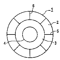
Fig. 1 shows a sensor tube consisting of an outer hard tube
and of an inner diffusion layer,
Fig. 2 shows a sensor tube consisting of an outer hard tube,
of a diffusion layer and of an inner transport tube.
Detailed Description
Figure 1 shows a sensor tube 1 which is designed for a leak
detection and location system (LDLS). It consists of an outer
hard pressure-stable tube 2 which is covered on the inside by
a diffusion layer 3. A conduit 4 remains free within the
sensor tube 1. If a substance to be detected, which has
emerged, for example, from a leak in a pipeline, arrives at
the sensor tube 1 from outside, it penetrates through holes 5,
which are arranged in the outer tube 2 and extend as far as
the diffusion layer 3, into the sensor tube 1. The substance
then diffuses through the diffusion layer 3 and passes into
-3-

CA 02433825 2003-06-05
the conduit 4. After the diffusion phase, a transport medium
is pumped through the conduit 4 for a defined timespan and the
substance is detected by means of a sensor at the end of the
sensor tube 1.
Figure 2 shows a sensor tube 6 which largely corresponds to
the sensor tube 1 of figure 1. The only difference is that the
diffusion layer 3 is located between an inner hard transport
tube 7 and the outer hard tube 2. Holes 8 which extend from
inside as far as the diffusion layer 3 are arranged in the
transport tube 7. The diffusion layer 3 is protected from a
high pressure of the transport medium by the inner transport
tube 7. The diffused-in substance passes from the diffusion
layer 3 out through the bores 8 into the conduit 4. The
transport tube 7 consists of a material which has only low
adsorption, so that the substance reaches the sensor
essentially completely.
-4-

CA 02433825 2003-06-05
Reference symbols
r
1 Sensor tube
2 Outer tube
3 Diffusion layer
4 Conduit
Hole in the outer tube
6 Sensor tube
7 Transport tube
8 Hole in the transport tube
-5-

Representative Drawing
A single figure which represents the drawing illustrating the invention.
Administrative Status

2024-08-01:As part of the Next Generation Patents (NGP) transition, the Canadian Patents Database (CPD) now contains a more detailed Event History, which replicates the Event Log of our new back-office solution.

Please note that "Inactive:" events refers to events no longer in use in our new back-office solution.

For a clearer understanding of the status of the application/patent presented on this page, the site Disclaimer , as well as the definitions for Patent , Event History , Maintenance Fee  and Payment History  should be consulted.

Event History

Description Date
Time Limit for Reversal Expired 2019-12-06
Common Representative Appointed 2019-10-30
Letter Sent 2018-12-06
Inactive: Correspondence - Transfer 2010-05-18
Grant by Issuance 2010-04-13
Inactive: Cover page published 2010-04-12
Pre-grant 2010-01-21
Inactive: Final fee received 2010-01-21
Notice of Allowance is Issued 2010-01-04
Letter Sent 2010-01-04
Notice of Allowance is Issued 2010-01-04
Inactive: Approved for allowance (AFA) 2009-12-31
Amendment Received - Voluntary Amendment 2009-06-16
Inactive: S.30(2) Rules - Examiner requisition 2009-01-06
Inactive: S.29 Rules - Examiner requisition 2009-01-06
Amendment Received - Voluntary Amendment 2008-06-20
Inactive: S.30(2) Rules - Examiner requisition 2007-12-27
Letter Sent 2007-04-04
Inactive: Multiple transfers 2007-02-20
Letter Sent 2006-12-07
Amendment Received - Voluntary Amendment 2006-12-05
All Requirements for Examination Determined Compliant 2006-11-21
Request for Examination Requirements Determined Compliant 2006-11-21
Request for Examination Received 2006-11-21
Letter Sent 2003-09-11
Inactive: Cover page published 2003-08-29
Inactive: Notice - National entry - No RFE 2003-08-27
Inactive: IPRP received 2003-08-22
Application Received - PCT 2003-08-08
Inactive: Single transfer 2003-07-16
National Entry Requirements Determined Compliant 2003-06-05
Application Published (Open to Public Inspection) 2002-06-13

Abandonment History

There is no abandonment history.

Maintenance Fee

The last payment was received on 2009-07-14

Note : If the full payment has not been received on or before the date indicated, a further fee may be required which may be one of the following

  • the reinstatement fee;
  • the late payment fee; or
  • additional fee to reverse deemed expiry.

Patent fees are adjusted on the 1st of January every year. The amounts above are the current amounts if received by December 31 of the current year.
Please refer to the CIPO Patent Fees web page to see all current fee amounts.

Owners on Record

Note: Records showing the ownership history in alphabetical order.

Current Owners on Record
AREVA NP GMBH
Past Owners on Record
PETER JAX
Past Owners that do not appear in the "Owners on Record" listing will appear in other documentation within the application.
Documents

To view selected files, please enter reCAPTCHA code :


To view images, click a link in the Document Description column (Temporarily unavailable). To download the documents, select one or more checkboxes in the first column and then click the "Download Selected in PDF format (Zip Archive)" or the "Download Selected as Single PDF" button.

List of published and non-published patent-specific documents on the CPD .

If you have any difficulty accessing content, you can call the Client Service Centre at 1-866-997-1936 or send them an e-mail at CIPO Client Service Centre.

({010=All Documents, 020=As Filed, 030=As Open to Public Inspection, 040=At Issuance, 050=Examination, 060=Incoming Correspondence, 070=Miscellaneous, 080=Outgoing Correspondence, 090=Payment})


Document
Description 
Date
(yyyy-mm-dd) 
Number of pages   Size of Image (KB) 
Drawings 2003-06-04 1 12
Claims 2003-06-04 1 25
Representative drawing 2003-06-04 1 3
Abstract 2003-06-04 1 9
Description 2003-06-04 5 174
Description 2008-06-19 6 176
Claims 2008-06-19 1 20
Description 2009-06-15 6 176
Claims 2009-06-15 1 20
Abstract 2010-02-08 1 9
Representative drawing 2010-03-23 1 3
Reminder of maintenance fee due 2003-08-26 1 106
Notice of National Entry 2003-08-26 1 189
Courtesy - Certificate of registration (related document(s)) 2003-09-10 1 106
Reminder - Request for Examination 2006-08-07 1 116
Acknowledgement of Request for Examination 2006-12-06 1 178
Commissioner's Notice - Application Found Allowable 2010-01-03 1 162
Maintenance Fee Notice 2019-01-16 1 181
PCT 2003-06-04 13 488
PCT 2003-06-04 4 176
Correspondence 2010-01-20 1 38