Note: Descriptions are shown in the official language in which they were submitted.
CA 02433868 2003-07-02
WD 02/058872 PCT/ILO1/01202
CUTTING INSERT
FIELD OF THE INVENTION
This invention relates to a generally square-shaped indexable cutting
insert with four cutting edges for mounting in milling cutters for either
slotting
operations or for left-hand and right-hand face milling of right-angled
corners in a
metal workpiece.
BACKGROUND OF THE INVENTION
In prior art milling cutters having square shaped indexable cutting
inserts for milling of right-angled corners in a metal workpiece, the cutting
inserts
are generally mounted in such a way that a reference plane formed by'the four
cutting edges generates a negative radial rake and a positive axial rake
(helix).
Each insert has a main cutting edge for milling in a workpiece a right-angled
corner, or shoulder, and a transversely directed secondary cutting edge. The
secondary cutting edge generally comprises two. sections, a section adjacent
the
main cutting edge that serves as a wiper for forming a smooth base wall of the
shoulder and a non-operative section. The cutting insert is designed and
mounted
in the milling cutter so that a small clearance is formed between the non-
operative
section and the base wall of the shoulder.
Since the cutting insert is mounted with a positive axial rake it
CA 02433868 2003-07-02
Wo 02/058872 PCT/ILO1/01202
-2-
preferably has a positive geometry in order to ensure a clearance between the
base
wall of the shoulder and the side flank of the insert adjacent the base wall
of the
shoulder. A cutting insert mounted as described above in a milling cutter
would
have a relatively small cutting edge wedge angle and a large radial relief
angle.
Consequently, during machining the cutting insert would be susceptible to
breakage
in the region of the cutting edge and the milling cutter can also suffer from
chatter.
It has been found that the cutting insert's performance can be improved when
the
clearance between the workpiece and the insert's side flank adjacent the
workpiece
is reduced in the region of the main cutting edge but is not reduced in the
region of
the wiper.
Of particular interest are generally square shaped cutting inserts with
four cutting edges that can be used for both left-hand and right-hand milling.
Such
a cutting insert is disclosed in U.S. Patent No. 5,951,212. However this
insert does
not provide for improved performance in the manner described.
It is an object of the present invention to provide a novel generally
square shaped cutting insert with four cutting edges that can be used for both
left-
hand and right-hand milling and that provides improved performance in the
manner
described.
SUMMARY OF THE INVENTION
In accordance with the present invention there is provided an indexable
cutting insert for use in milling cutters comprising:
a top surface, a bottom surface and M substantially identical side surfaces
extending between the bottom surface and the top surface, the top surface
having
the general shape of an M-sided polygon in a top view of the cutting insert;
each side surface being located between two corner side surfaces;
each side surface sloping outwardly from the bottom surface toward the top
surface and intersecting with the top surface at a cutting edge, the cutting
edge
being located between two corner edges and being substantially parallel to the
CA 02433868 2003-07-02
WO 02/058872 PCT/ILO1/01202
-3-
bottom surface;
each cutting edge comprising a primary cutting edge extending between two
wipers, each wiper being adjacent a corner edge;
each side surface comprising at least two component surfaces, a first relief
surface adjacent the primary cutting edge and a second relief surface merging
with
the first relief surface at a boundary line and intersecting with the top
surface at the
two wipers; wherein
M is an integral multiple of four and the first relief surface has a width
dimension measured perpendicularly to the cutting edge, the width dimension
having a minimum value proximal to the two wipers and a maximum value at a
central region of the cutting edge.
In accordance with the present invention, the first relief surface forms a
first
non-zero relief angle with a line perpendicular to a reference plane
containing the
cutting edge associated with each side surface, and the second relief surface
forms,
in the region of the first and second wipers, a second non-zero relief angle,
wherein
the second relief angle is greater than the first relief angle.
In accordance with a specific embodiment of the present invention, the
boundary line of each side surface comprises two equal substantially straight
boundary line sections meeting at a central region of the side surface
Further in accordance with a specific embodiment of the present invention,
the second relief surface comprises two similar constituent relief surfaces
merging
at the central region of the side surface.
Preferably, each one of the two constituent relief surfaces slopes outwardly
from the corner side surfaces towards the central region of the side surface.
If desired, the first relief surface is ground.
Further if desired, the two constituent relief surfaces are ground.
Still yet further if desired, the second relief surface is provided with a
recess
centrally located therein.
In accordance with the present invention the cutting insert has a through bore
CA 02433868 2003-07-02
WO 02/058872 PCT/ILO1/01202
-4-
passing through the top and bottom surfaces.
Preferably, the cutting insert comprises a pressed and sintered powder body.
In accordance with a preferred embodiment of the present invention, M is
equal to four.
In accordance with an embodiment of the present invention, the second relief
surface is provided with a recess centrally located therein.
BRIEF DESCRIPTION OF THE DRAWINGS
For a better understanding the invention will now be described, by way
of example only, with reference to the accompanying drawings in which:
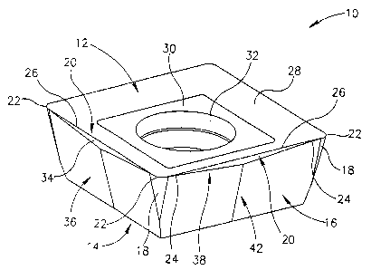
Fig. 1 is a perspective view of the cutting insert in accordance with the
present invention;
Fig. 2 is a side view of the cutting insert illustrated in Fig. 1;
Fig. 3 is a top view of the cutting insert illustrated in Fig. l;
Fig. 4 is a cross section view of a portion of the cutting insert along the
line
IV-IV in Fig. 3;
Fig. 5 is a cross section view of a portion of the cutting insert along the
line
V-V in Fig. 3;
Fig. 6 is a perspective view of the cutting insert in accordance with the
present invention with a recess in each second relief surface;
Fig. 7 is slotting cutter in which are seated cutting inserts in accordance
with
the present invention; and
Fig. 8 is face-milling cutter in which are seated cutting inserts in
accordance
with the present invention.
DETAILED DESCRIPTION OF PREFERRED EMBODIMENTS
Attention is first drawn to Figs. 1 to 5. T'he cutting insert 10 in
accordance with the present invention has a top surface 12, a bottom surface
14 and
four substantially identical side surfaces 16 extending between the bottom
surface
CA 02433868 2003-07-02
WO 02/058872 PCT/ILO1/01202
-5-
14 and the top surface 12. The cutting insert is preferably manufactured by
pressing and sintering a powder body. As seen in Fig. 3 the top surface 12 is
generally square-shaped in a top view of the cutting insert 10. Each side
surface 16
extends between two corner side surfaces 18. The corner side surfaces 18 are
radiused, having a maximum radius proximal to the top surface 12 and
decreasing
to a minimum radius proximal to the bottom surface. Each side surface 18
slopes
outwardly from the bottom surface 14 toward the top surface 12 and intersects
the
top surface at a cutting edge 20. In other words, and as can be seen in Figs.
1 and
2, the cutting insert 10 has a positive geometry, so that each side surface 16
forms
an acute wedge angle ~i (as will be explained in greater detail below, in
accordance
with the present invention ~ takes on two values ~1 and ~2) with the top
surface 12
of the cutting insert 10. Each cutting edge 20 is substantially parallel to
the bottom
surface 14 and extends between two radiused corner edges 22. The cutting edge
20
comprises two portions, two wipers 24, or auxiliary cutting edges, adjacent
the
corner edges 22 and a primary cutting edge 26 extending between the two wipers
24. The top surface 12 comprises a chip rake surface 28 that slopes downwardly
and inwardly from the cutting edges 20, the wipers 24 and the comer edges 22
toward a central region 30 of the top surface 12. The primary cutting edges
26, the
wipers 24 and the corner edges 22 are all capable of cutting and therefore the
entire
circumference of the top surface 12 forms a continuous cutting edge from which
the chip rake surface 28 slopes downwardly and inwardly. The cutting insert 10
has
a through bore 32 passing through central region 30 of the top surface 12 and
through the bottom surface 14 for receiving a clamping screw for clamping the
cutting insert 10 in an insert pocket of a cutting tool.
In order to strengthen the cutting insert 10 in the region of the primary
cutting edges 26, each side surface 16 is divided into two component surfaces,
a
first relief surface 34 adjacent the primary cutting edge 26 and a second
relief
surface 36 merging with the first relief surface at a boundary line 38 and
intersecting with the top surface 12 at the two wipers 24 on either side of
the
CA 02433868 2003-07-02
WO 02/058872 PCT/ILO1/01202
-6-
primary cutting edge 26.
The first relief surface 34 has a width dimension W measured perpendicularly
to the cutting edge 20 that, in accordance with a first aspect of the present
invention, has a minimum value proximal to the two corner edges 22 and a
maximum value at a central region 40 of the cutting edge 20. With this
construction, as can be seen in the figures, the first relief surface 34 is
generally
triangular in shape. Furthermore, this construction imparts to the cutting
insert 10 a
symmetry that enables it to be used as either a right handed or left handed
cutting
insert.
A second aspect of the present invention concerns the relief, or
clearance, of the side surfaces 16 of the cutting insert 10. In the
description and
claims, a reference plane P containing the cutting edge 20 associated with
each side
surface 16 is defined. Since each cutting edge 20 is substantially parallel to
the
bottom surface 14, the reference plane P is also parallel to the bottom
surface 14 of
the cutting insert 10 as can be seen in Fig. 2. In accordance with a second
aspect of
the present invention, the first relief surface 34 forms a first relief angle
a1 with a
line N perpendicular to the reference plane P, and the second relief surface
36
forms, in the region of the wipers 24, a second relief angle oc2, wherein the
second
relief angle a2 is greater than the first relief angle ocl. As can be seen in
Figs. 4 and
5, in accordance with this aspect of the invention, the wedge angle al in the
region
of the primary cutting edge 26 of each side surface 16 is greater than the
wedge
angle ~2 in the region of the wipers 24. Clearly, the presence of the first
relief
surface 34 strengthens the cutting insert 10 in the region of the primary
cutting edge
26 due to the increased wedge angle. In accordance with a specific non-binding
example, a2 = 14° and al = 8° thereby increasing the clearance
at the primary
cutting edge by 6° whilst strengthening the cutting insert by
increasing the wedge
angle along the primary cutting edge 26.
As can be seen in the figures, the boundary line 38 of each side surface
16 comprises two equal boundary line sections 38a, 38b meeting at a central
region
CA 02433868 2003-07-02
Wo 02/058872 PCT/ILO1/01202
42 of the side surface 16. In accordance with a preferred embodiment of the
present invention, the boundary line sections 38a, 38b are straight lines. In
a similar
manner, the second relief surface 36 comprises two similar constituent relief
surfaces 36a, 36b merging at the central region 42 of the side surface 16. For
each
side surface 16, each one of the two constituent relief surfaces 36a, 36b
slopes
outwardly from adjacent corner side surfaces 18 towards the central region 42
of
the side surface where they merge.
Although for many purposes it will suffice to manufacture the cutting
insert illustrated in Figs. 1 to 5 by pressing and sintering without any
further
processing, greater accuracy can be obtained by grinding some of the surfaces.
Therefore, if desired, the first relief surface 34 is a ground surface.
Further if
desired, the two constituent relief surfaces 36a, 36b are ground surfaces.
Attention is now drawn to Fig. 6, illustrating the cutting insert 10 in
accordance with the teachings of the present invention, in which each second
relief
surface 36 is provided with a recess 44 centrally located therein. Each
constituent
relief surface 36a, 36b is divided into two regions, an upper region 46a, 46b
and a
lower region 48a, 48b. The lower regions 48a, 48b of the two constituent
relief
surfaces 36a, 36b of a given side surface 16 slope outwardly 'from adjacent
corner
side surfaces 18 towards the recess 44. On the other hand, the upper regions
46a,
46b of the two constituent relief surfaces 36a, 36b merge at an upper central
region
50 of the side surface 16 above the recess 44.
Figs. 7 and 8, illustrate preferred applications of the cutting insert 10 of
the present invention. Fig. 7 shows a slotting cutter 52, in which only three
identical radially mounted cutting inserts 10 (10', 10") are shown. The
cutting
inserts 10 are mounted as both left-hand inserts 10' and right-hand inserts
10". The
cutting inserts mounted as left-hand inserts 10' have an operative wiper 24'
proximate to one face 53a of the slotting cuter 52, whereas the cutting
inserts
mounted as right-hand inserts 10" have an operative wiper 24" proximate to the
other face 53b of the slotting cuter 52. Fig. 8 shows a face-milling cutter 54
for
CA 02433868 2003-07-02
WO 02/058872 PCT/ILO1/01202
-g-
right-handed milling of a work piece, using cutting inserts 10 in accordance
with
the present invention (only one insert is shown). In a similar manner, cutting
inserts 10 in accordance with the present invention can be used in a face-
milling
cutter for left-handed milling of a work piece.
Although the present invention has been described to a certain degree of
particularity, it should be understood that various modifications and
alterations can
be made without departing from the spirit or scope of the invention as
hereinafter
claimed. For example, the invention has been described with respect to a
cutting
insert that is generally square-shaped in a top view of the cutting insert.
However,
the invention is by no means restricted to a cutting insert with a generally
square-
shaped geometry. It will be appreciated that the invention applies equally
well to a
cutting insert that is generally octagonally-shaped in a top view of the
cutting insert.
In general, the invention applies equally well to a cutting insert that is
generally M-
shaped in a top view of the cutting insert, where M is an integral multiple of
four.