Note: Descriptions are shown in the official language in which they were submitted.
CA 02434177 2003-07-09
WO 02/055218 PCT/US02/00931
SHEET COATER
Field of the Invention
[0001] This invention relates to devices and methods for coating substrates of
limited
length and for improving the uniformity of non-uniform or defective coatings.
Background
[0002] There are many known methods and devices for coating a moving web and
other
fixed or moving endless substrates, and for smoothing the resulting coating.
Several are
described in Booth, G. L., "The Coating Machine", Pulp and Paper Manufacture,
Vol. 8,
Coating, Converting and Processes, pp 76 - 87 (Third Edition, 1990) and in
Booth, G. L.,
Evolution of Coating, Vol. 1 (Gorham International Inc.). For example,
multiroll coaters
(see, e.g., U.S. Patent Nos. 2,105,488; 2,105,981; 3,018,757; 4569,864 and
5,536,314) can
be used to provide thin coatings. Multiroll coaters are shown by Booth and are
reviewed
in Benjamin, D. F., Anderson, T. J. and Scriven, L. E. "Multiple Roll Systems:
Steady -
State Operation", AIChE J., V41, p. 1045 (1995); and Benjamin, D. F.,
Anderson, T. J.
and Scriven, L. E., "Multiple Roll Systems: Residence Times and Dynamic
Response",
AIChE J., V41, p. 2198 (1995). Commercially available forward-roll transfer
coaters
typically use a series of three to seven counter rotating rolls to transfer a
coating liquid
from a reservoir to a web via the rolls. These coaters can apply silicone
release liner
coatings at wet coating thickness as thin as about 0.5 to about 2 micrometers.
The desired
coating caliper and quality are obtained by artfully setting roll gaps, roll
speed ratios and
nipping pressures. Another type of coating device is shown in U.S. Patent No.
4,569,864,
which describes a coating device in which a thick, continuous premetered
coating is
applied by an extrusion nozzle to a first rotating roll and then transferred
by one or more
additional rolls to a faster moving web.
[0003] Devices for coating substrates of limited length (e.g., small sheets)
are also
available, and can be used to prepare experimental or test coatings without
requiring set up
or operation of a web coating apparatus. These are commonly referred to as
hand spread
devices, and consist of a knifing apparatus in which a gap is set between a
knifing edge
-1-
CA 02434177 2003-07-09
WO 02/055218 PCT/US02/00931
and a bed plate, and a sheet is pulled through the gap while it is flooded
with coating
liquid. Another example is a wire-wound rod coater known as a "Mayer Bar" (see
U.S.
Patent No. 1,043,021 to Mayer) which can be used to make manual hand spreads
on small
test sheets.
Summary of the Invention
[0004] Many current coating applications require extremely thin coatings,
e.g., on the
order of 10 micrometers or less. For such thin coatings, it can be very
difficult to form
hand spreads having the desired caliper and coating quality. When it is not
practical to
prepare a suitable hand spread, then typically a coating run must be set up on
a suitable
web coating apparatus. This takes time and can generate substantial quantities
of costly
scrap. Additionally, large quantities of raw materials are required for
continuous coating.
[0005] For thicker coatings, current hand spread techniques are somewhat more
suitable.
However, even thick hand spread coatings are often deficient in coating
quality, caliper
uniformity or precise attainment of a target average caliper.
[0006] The present invention provides, in one aspect, coating devices and
methods for
coating substrates of limited length. In one embodiment, a device of the
invention
comprises:
a) a rotating support having a surface, the surface at least partially covered
with a removable substrate of limited length;
b) at least one pick-and-place roll that is nipped against the substrate on
the
support and whose period of rotation is not equal to the period of rotation
of the support;
c) a coating applicator for applying a quantity of coating liquid to the
substrate or to the pick-and-place roll; and
d) a motion device that rotates the support and substrate for a plurality of
revolutions whereby wetted surface portions of the pick-and-place roll
repeatedly contact the substrate.
[0007] In another embodiment, a method of the invention comprises:
a) providing a rotating support (e.g., a mounting roll) having a surface, the
surface at least partially covered with a removable substrate of limited
length and, in either order:
-2-
CA 02434177 2003-07-09
WO 02/055218 PCT/US02/00931
i) nipping the substrate between the support and at least one pick-and-
place roll whose period of rotation is not equal to the period of
rotation of the support; and
ii) applying a quantity of coating liquid to the substrate or to the pick-
and-place roll; and
b) rotating the support and substrate for a plurality of revolutions whereby
wetted surface portions of the pick-and-place roll repeatedly contact the
substrate.
[0008] In particularly preferred embodiments of the devices and methods of the
invention, (a) the coating is applied unevenly (e.g., with repeatedly varying,
discontinuous
or intermittent caliper variations), (b) two or more pick-and-place rolls are
employed, (c)
the rotational speed of at least one pick-and-place roll is varied with
respect to the
rotational speed of the support or other pick-and-place roll, (d) at least one
pick-and-place
roll period of rotation is not periodically related to the period of rotation
of the support or
(e) at least one pick-and-place roll period of rotation is not periodically
related to the
period or rotation of at least one other pick-and-place roll.
[0009] The devices and methods of the invention facilitate the formation of
continuous
void-free, uniform and extremely thin coatings on substrates of limited length
using low-
cost equipment.
Brief Description of the Drawing
[0010] Fig. la is a schematic side view of a device of the invention.
[0011] Fig. 1b is a schematic side view of another device of the invention.
[0012] Fig. 2 is a perspective view of a sheet of limited length mounted upon
a rotatable
support.
[0013] Fig. 3 is a perspective view of a device of the invention.
[0014] Fig. 4 is an improvement diagram illustrating the minimum caliper that
can be
obtained by periodically applying cross-web coating stripes to a substrate
mounted in a
device of the invention having one rotating support and one pick-and-place
roll and
rotating the support for 20 revolutions, using various dimensionless roll
sizes and
dimensionless stripe widths.
[0015] Fig. 5 is an improvement diagram like that of Fig. 4, but after 200
revolutions.
-3-
CA 02434177 2003-07-09
WO 02/055218 PCT/US02/00931
[0016] Fig. 6 is an improvement diagram like that of Fig. 4, but for a device
of the
invention having one rotating support and two pick-and-place rolls.
[0017] Fig. 7 is an improvement diagram like that of Fig. 4, but after 40
revolutions.
[0018] Fig. 8 is an improvement diagram like that of Fig. 4, with an expanded
horizontal axis.
[0019] Fig. 9 is an improvement diagram like that of Fig. 8, but after 100
revolutions.
[0020] Fig. 10 is an improvement diagram illustrating the dimensionless range
minimum as a function of roll size for 2% speed variations of the pick-and-
place rolls.
[0021] Fig. 11 is an improvement diagram illustrating the dimensionless range
minimum that can be obtained by periodically applying a cross-web coating
stripe of
constant dimensionless stripe width to a substrate mounted in a device of the
invention
having one rotating support and two pick-and-place rolls and rotating the
support for 10
revolutions, using various dimensionless roll sizes for the two pick-and-place
rolls.
[0022] Fig. 12 is an improvement diagram like that of Fig. 11, but after 20
revolutions.
[0023] Fig. 13 is an improvement diagram like that of Fig. 11, but with a 2%
variation
in relative roll speeds.
Detailed Description
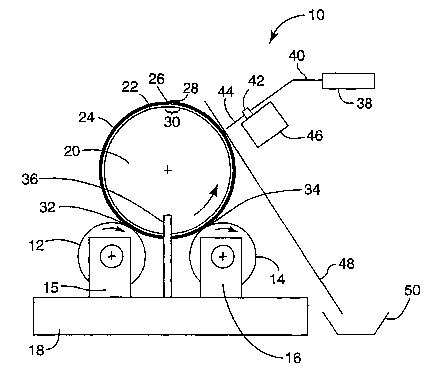
[0024] Referring to Fig. la, a device 10 of the invention is shown in cross
sectional
view. Steel "pick-and-place" or contacting rolls 12 and 14 are supported by
low friction
bearings (not shown in Fig. la) housed in pedestals 15 and 16 atop base 18.
Rolls 12 and
14 are spaced horizontally from one another and in parallel. In the embodiment
shown in
Fig. la, contacting rolls 12 and 14 are the same size. If desired, more than
two such rolls
can be employed. Roll 12 or roll 14 or both can be driven at speeds of, e.g.,
1 to 1000
revolutions per minute by a variable drive device not shown in Fig. la.
Rotating support
or mounting roll 20 is surrounded by rubber cover 22 and sheet 24. Sheet 24
has a limited
length, and ends 26, 28 of sheet 24 overlap slightly at region 30. Roll 20
rests in the gap
between and is supported by rolls 12 and 14. The diameters and axes of
contacting rolls
12 and 14 and of mounting roll 20 preferably are carefully controlled and
aligned, with
diameters and surface straightness tolerances of ~10 micrometers being
preferred. The
weight of roll 20 provides a nipping force that promotes intimate contact
between sheet 24
and rolls 12 and 14 in nip points 32 and 34. Retainer stop 36 and an
additional retainer
-4-
CA 02434177 2003-07-09
WO 02/055218 PCT/US02/00931
stop (not shown in Fig. la) on the other end of roll 20 prevent sideways axial
movement
of roll 20. When driven roll 12 rotates, rolls 14 and 20 are driven by surface
traction at
nearly the same surface speed as roll 12.
[0025] Coating liquid from syringe pump 38 is supplied through supply line 40
and feed
block 42 to needle 44. Oscillating mechanism 46 moves needle 44 back and forth
across
the surface of roll 20. Rest positions are provided at each end of the
oscillation stroke.
Deflector plate 48 and an additional deflector plate (not shown in Fig. 1a) on
the other end
of roll 20 intercept the flow of coating liquid at each end of the stroke of
mechanism 46.
The gap between the deflector plates controls the coating width on roll 20,
and the plates
drain excess coating liquid into a collection trough 50.
[0026] Fig. 1b shows a device of the invention 60 like device 10 in Fig. la,
but in which
roll 14 is absent and roll 20 lies directly above roll 12. Both rolls 12 and
20 are carried on
low friction bearings 62. The nip force at nip point 64 is adjusted using a
conventional
roll gap controller 66.
[0027] Fig. 2 is a perspective view of a sheet 24 of limited length mounted
upon
rotatable mounting roll 20. As shown in Fig. 2, the ends 26, 28 of sheet 24
are placed in
abutting relationship. However, the ends 26, 28 can overlap as shown in Fig.
la and Fig.
1b or can have a small gap between them if desired. Axle 67 supports roll 20.
[0028] Fig. 3 is a perspective view of a device 70 of the invention. Device 70
is like
device 10 of Fig. la, but is designed so that the coating liquid is applied to
a raised portion
68 on roll 12 rather than to sheet 24 on roll 20. Device 70 is portable and
can be used, for
example, on a benchtop. Roll 20 lies between and is supported by rolls 12 and
14. Rolls
12 and 14 are carried by low friction bearings 62 in pedestals 15 and 16,
respectively atop
base 18. Rotating retainer stop 35 atop support post 37 limits sideways
movement of roll
20. Rotating force is supplied to roll 12 by variable speed drive motor 72
operating
through coupling 74. The speed of rotation of motor 72 (and thence of roll 12)
is
controlled using power switch 75 and potentiometer 76 in housing 78. Pilot
light 77
indicates that motor 72 is energized. Oscillating mechanism 46 moves supply
line 40 and
needle 44 back and forth along rails 80 due to the action of rotating spiral
wound lead
screw 82. Power switch 84 and a conventional speed regulation device (not
shown in Fig.
3) regulate the speed of lead screw 82 and the rate of oscillation of
mechanism 46. Bubble
-5-
CA 02434177 2003-07-09
14-0~-2003 / ~. ' /,S
US0200931
- .: ~ ~d~9~ P~
levels 86 and leveling screws 88 assist in leveling device 70. Handle 90
enables device 70
to be moved by hand from place to place.
[0029] The basic principles of operation of the devices shown in Fig. la
through Fig. 3
are described in detail in the above-mentioned U.S. Patent Application Serial
No.
09/757,955 filed January 10, 2001, and in pending U.S. Patent Application
Serial No. '
03 / '~ fir' a r~u .1
c'Ife ~~6~993~ filed and entitled COATING
DEVICE AND METHOD USING PICK-AND-PLACE DEVICES HAVING EQUAL OR
SUBSTANTIALLY EQUAL PERIODS, the entire disclosure of which is incorporated by
reference herein.
[0030] Sample sheet coating can be accomplished using the devices of the
invention by
initially mounting sheet 24 on roll 20 using a suitable mounting technique. If
sheet 24 has
suitable dielectric properties, then static electrical forces usually will be
sufficient to hold
sheet 24 in place without other fastening measures being required. Next, roll
20 is placed
adjacent contacting roll 12 and other contacting rolls such as roll 14 if
present, so that
sheet 24 is nipped between roll 20 and the contacting roll or rolls.
[0031] The total volume of coating liquid needed to achieve the desired
coating caliper
can be calculated in advance. Assuming equal film splits at the nip points,
e.g., the nip
points 32 and 34 in Fig. la, the total coating liquid volume will equal the
desired caliper
times the wetted surface area. This wetted surface area will equal the wetted
surface of all
the contacting roils, e.g., rolls 12 and 14 plus the wetted surface on roll
20. The desired
volume of coating liquid is next applied as one or a plurality of liquid
stripes across the
length of at least one of the contacting rolls, e.g., roll 12 or roll 14, or
across the face of
sheet 24 on roll 20. The coating liquid application can conveniently be
carried out by
flowing the coating liquid through needle 44 while needle 44 traverses back
and forth. By
varying the number of stripes and the flow rate from needle 44, the desired
final caliper on
sheet 24 can be very accurately controlled. The applied coating liquid stripes
can be
placed in random or in specific locations on a contacting roll or rolls or on
sheet 24.
Improved uniformity for a set number of rotations may be achieved if the
stripe width and
placement are optimized as described in more detail below. Stripe coating is
preferred
over attempting to apply a uniform coating to a contacting roll or to sheet
24, because it is
much easier to apply a nonuniform coating of thicker stripes than to apply a
uniform thin
-6-
AMENDED SHEET
CA 02434177 2003-07-09
14-0~4-2003 US0200931
coating. The flow rate of the liquid preferably is held constant during
application in order
to promote good cross web uniformity in the final coating.
[0032] The initial lengthwise uneven coating on the contacting roll or on
sheet 24 is
converted to a uniform coating by causing the various device rolls to revolve
for a
S plurality of revolutions, whereupon wetted and to be wetted surface portions
of the sheet
24 and the contacting roll or rolls will contact and re-contact one another at
successively
laced bt~c~
different positions. This causes the coating liquid to be picked up from and ~
onto
the sheet 24. The coating quickly becomes much more uniform. For example, in
the
device shown in Fig. 3, when the variable speed drive motor 72 is energized
then the
contacting rolls 12 and 14 and mounting roll 20 all rotate at approximately
the same
surface speed. A very uniform caliper coating is obtained by rotating roll 20
for a suitable
number of revolutions (e.g., 10 or more, 20 or more or even 100 or more
revolutions) and
by exercising appropriate control of various factors discussed below.
Following
completion of the desired number of revolutions, sheet 24 is removed from roll
20 and
permitted to dry or harden if required. To assist in removal of sheet 24, roll
20 can be
lifted away from the device of the invention and placed on a suitable stand or
benchtop.
However, due to the weight of roll 20, it rnay be somewhat difficult to pick
up roll 20 by
hand. The devices of the invention can be equipped with a suitable lifting
device (e.g.,
pneumatically-operated lifting jacks that raise roll 20) to assist in removal
of sheet 24.
[0033] Preferably the respective circumferences of rolls 20 and 12 (and the
respective
circumferences of roll 20 and additional contacting rolls such as roll 14 if
present) are not
expressed by a fraction in which the numerator and the denominator are
integers ranging
from one to twenty. However, if the respective roll circumferences are integer
multiples,
we have found ways to achieve uniformity using the improvement diagrams
discussed
below. We have also found ways to minimize or reduce the number of roll
revolutions
needed to achieve uniformity. Investigation of a very large number of
operational modes
for the devices and methods of the invention has been accomplished through the
use of
computer modeling.
[0034] The improvement diagram in Fig. 4 further illustrates features of our
invention.
Fig. 4 shows results that can be obtained by applying coating liquid to
mounting roll 20 or
contacting roll 12 of device 60 in Fig. 1b in a variety of operational modes.
The modes
involve variation in the contacting roll size and the width of an applied
stripe of coating
AMENDED SHEET
CA 02434177 2003-07-09
WO 02/055218 PCT/US02/00931
liquid. In Fig. 4 and the other improvement diagrams depicted herein, a
uniformity metric
referred to as the "dimensionless minimum caliper" is calculated by dividing
the final
minimum coating caliper found on the surface of sheet 24 by the final average
coating
caliper. The improvement diagram in Fig. 4 is a shaded contour plot. The
shadings
assigned to various dimensionless minimum caliper ranges are noted in the
legend. Dark
gray regions represent dimensionless minimum caliper values in the range of 0
to 0.3.
Black regions represent dimensionless minimum caliper values in the range of
0.3 to 0.6.
Light gray regions represent dimensionless minimum caliper values in the range
of 0.6 to
0.9. White regions represent dimensionless minimum caliper values in the range
of 0.9 to
1. A dimensionless minimum caliper value of 0.0 indicates there is at least
one uncoated
spot on sheet 24 after operation of device 60. A dimensionless minimum caliper
value of
1.0 indicates a perfectly uniform coating on sheet 24 after operation of
device 60.
[0035] It is possible to apply very thick stripes of coating. These will often
spread into
wider stripes after the first passage through a nip. We define stripe width as
the width
immediately after the first passage of the stripe through a nip. We also
define two
dimensionless parameters (referred to in Fig. 4 as the "dimensionless roll
size" and
"dimensionless stripe width") by dividing the actual contacting roll 12
circumference and
the actual stripe width by the actual roll 20 circumference. Every point on
the
improvement diagram of Fig. 4 thus represents a dimensionless roll 12
circumference and
a dimensionless stripe width for the application of a single stripe of coating
liquid and
operation of device 60 for 20 revolutions. Fig. 4 shows the results for
combinations of
dimensionless roll 12 sizes from 0 to 1 and dimensionless stripe widths from 0
to 1. Any
point location on the improvement diagram represents a pair of choices for
these variables.
The shading at that point location represents the attained dimensionless
minimum caliper.
White regions in Fig. 4 thus represent operating conditions where the
combination of roll
12 size and applied stripe width results in "good uniformity" (viz., a
dimensionless
minimum coating caliper greater than 0.9) across the coated face of sheet 24.
Dark gray
regions in Fig. 4 represent operating conditions where the combination of roll
12 size and
applied stripe width results in one or more voids or near voids on the coated
face of sheet
24.
[0036] While poor choices and impractical stripe widths dominate most of the
areas of
the improvement diagram for this simple two roll device, surprisingly good
choices of roll
_g_
CA 02434177 2003-07-09
WO 02/055218 PCT/US02/00931
size and stripe width are found in Fig. 4. Examples include regions 102, 104
and 106 in
Fig. a
[0037] Roll 12 sizes that are integer multiples and proper fractions of the
roll 20 size
preferably are avoided unless an appropriate value of stripe width is chosen
and an
adequate number of roll 20 revolutions is used. Fig. 5 is an improvement
diagram
showing the results obtained for a two roll device (roll 20 plus roll 12)
after 200
revolutions of roll 20. The improvement diagram in Fig. 5 has much larger
white regions
than the improvement diagram in Fig. 4, illustrating the beneficial effect of
operating the
devices of the invention for a greater number of revolutions. Operating
conditions in Fig.
5 in which roll 20 is l, 2, 3, 4; 5, 6, 7, 8, 9, or 10 times larger than roll
12 are not desirable.
These correspond to dimensionless roll 12 sizes of l, 1/2, 1/3, 1/4, 1/5, 1/6,
1/7, 1/8, 1/9,
and 1/10 and are shown as dark gray, black or light gray vertically-extending
regions in
Fig. 5. Other dimensionless roll 12 sizes are also undesirable, such as those
shown by the
other light gray and black areas in Fig. 5. For example, dimensionless roll
sizes
corresponding to fractional ratios of 2/5, 2/7 and 2/9 are undesirable along
with roll sizes
corresponding to the fractional ratios 3/5, 3/7, 3/8, 3/10 and 3/11.
[0038] While the above-mentioned roll sizes are undesirable, in special cases
good
uniformity can be obtained for these roll sizes when the stripe width equals a
special
value, called the "minimum dimensionless stripe width". An integer multiple of
this value
also produces good uniformity. Examples of such minimum dimensionless stripe
widths
are illustrated on Fig. 5 as regions 108, 109, 110, 111, 112, 113, 114 and
115. These can
give good uniformity at dimensionless roll sizes of 1/2, 1/3, 1/4, 1/5, 2/3,
4/5, 3/5 and 2/5,
respectively even though operation above or below these stripe width ranges
may not.
[0039] Fig. 5 illustrates results obtained using a relatively large number of
revolutions.
However, in appropriate cases thousands or even tens of thousands of
revolutions can be
employed, so long as the coating liquid is not constrained by factors that
would prevent
long running times. Drying, curing, gelation, crystallization or a phase
change occurring
with the passage of time may impose limitations. If the coating liquid
contains a volatile
component, the time necessary to achieve hundreds or thousands of revolutions
may allow
drying to proceed to the extent that the liquid may solidify. A phase change
for any reason
while the rolls are rotating usually results in disruptions and patterns in
the applied
-9-
CA 02434177 2003-07-09
WO 02/055218 PCT/US02/00931
coating. Therefore, it is generally preferable to produce the desired degree
of coating
uniformity in as few revolutions as possible.
[0040] For industrial coating applications, we prefer to use dimensionless
stripe widths
that are less than about 0.2, and more preferably between about 0.05 and about
0.15. In
general, narrow stripe widths are easier to produce than wider stripe widths.
However,
wider stripe widths (e.g., widths greater than about 0.2) can be used if
desired.
[0041] When stripe width ratios of 0.1 to 0.2 can be applied, one preferred
range of
choices for the dimensionless roll 12 size in Fig. 5 lies between 0.205 and
0.24, or
generally between the fractions 1/5 and 1/4. Other preferred dimensionless
roll 12 size
ranges for these and wider stripe width ratios would have a size between 0.02
to 0.195,
0.255 to 0.28, 0.34 to 0.36 and 0.44 to 0.48.
[0042] Through extensive investigations, we have found the following
generalizations.
For every dimensionless roll 12 size that equals an proper fraction (e.g.,
dimensionless roll
sizes such as 1/2, 2/5, 11/20) there exists a minimum dimensionless stripe
width less than
1.0, such that good uniformity will be obtained if sufficient revolutions of
roll 20 are used.
The exception is for the fractions n/1 where n is an integer. Exceeding the
minimum
dimensionless stripe width may result in but is not sufficient to insure good
uniformity.
For any given fractional roll size, good uniformity will only be obtained if a
sufficient
number of revolutions of roll 20 have occurred. Likewise, after any fixed
number of
revolutions, only a limited range of stripe ratios provide good uniformity.
[0043] Knowledge of the existence of these minimum dimensionless stripe widths
allows an appropriate stripe width to be selected when the dimensionless roll
size choices
are restricted. Likewise, this knowledge often allows a desired caliper to be
obtained at a
given dimensionless roll size by choosing narrower or wider stripe widths from
amongst a
set of available stripe width choices. When such sets exist, then the more
easily produced
narrower stripe widths can be selected in preference to wider stripe widths.
[0044] A value we describe as the "dimensionless range minimum" (defined as
the
lowest dimensionless minimum caliper found when the dimensionless stripe width
varies
from 0.05 to 0.15) can be used to select a preferred range of dimensionless
roll sizes. This
range is especially preferred for industrial use, but should not be considered
a constraint.
Operation outside the dimensionless range minimum is acceptable as well.
-10-
CA 02434177 2003-07-09
WO 02/055218 PCT/US02/00931
[0045] By employing more rolls than just roll 12 bearing against mounting roll
20, an
expanded range of regions with good coating caliper is obtained. Fig. 6 is an
improvement diagram for 20 revolutions for a three roll device (roll 20 plus
rolls 12 and
14) such as is shown in Fig. 1b where rolls 12 and 14 are of equal size:
Comparison of
Fig. 4 and Fig. 6 shows enlarged or new regions of good coating caliper,
especially for
dimensionless roll sizes below 0.5. However, if the dimensionless stripe width
is limited
to between 0.05 and 0.15, there is only a modest expansion of the preferred
white regions
on the contour plot in Fig. 6. One might expect that for small rolls the
results obtained
using two contacting rolls (viz., a three roll device) would be equivalent to
those obtained
by running one roll (viz., in a two roll device) for twice as many roll 20
revolutions. Fig.
7 shows the results obtained in a two roll device after 40 revolutions of roll
20. It should
be noted that the vertical axis of Fig. 7 shows dimensionless stripe widths
only from 0 to
0.5. Comparison of Fig. 6 and Fig. 7 shows that it is actually better to use a
two roll
device having only one contacting roll for 40 revolutions of roll 20, than to
use a three roll
device employing two equal size contacting rolls for 20 revolutions of roll
20.
[0046] Fig. 8 and Fig. 9 show improvement diagrams for 20 and 100 revolutions
of roll
in the two roll device of Fig. la. Both diagrams employ an expanded range of
dimensionless roll size ratios (from 0 to 2) and a reduced range of
dimensionless stripe
widths (from 0 to 0.5). Comparison of Fig. 8 and Fig. 9 shows that
dimensionless roll 12
20 size ratios less than 1.0 are preferred over ratios greater than 1Ø
However, good
uniformity can be obtained using ratios larger than 1.0 if a greater number of
roll 20
revolutions is used.
[0047] Further performance improvements can be obtained by operating the
contacting
rolls at different speeds using a fixed or variable constant speed
differential. The
rotational period of the surface of a rotating body relative to another
rotating body can also
be changed by varying the size of the first body while holding its surface
speed constant
(e.g., by inflating or deflating or otherwise expanding or shrinking the
roll). If the roll is
constructed from a thermally expanding material, then the roll size (and the
roll period)
can also be modified by operating the roll at differing temperatures. Also,
the position of
a roll can be varied during operation. For example, a force can be applied to
the end of
and parallel to shaft 67 of roll 20 to cause roll 20 to oscillate back and
forth relative to the
contact faces of the rolls 12 and 14. This movement will induce sideways,
cross-sheet
-11-
CA 02434177 2003-07-09
WO 02/055218 PCT/US02/00931
movement of liquid and improve overall coating uniformity, especially if the
initially
applied stripe was not perfectly uniform. All of the above variations are
useful, and all
can be used to affect and improve the performance of the devices and methods
of the
invention and the uniformity of the caliper of the finished coating.
S [0048] Very small variations in relative roll surface periods or surface
speeds have been
found to be useful. Variation can be accomplished, for example, by
independently driving
the rolls with separate motors and electrically varying the motor speeds.
Those skilled in
the art will appreciate that a variety of mechanical speed variation devices
can also be
employed, including variable speed transmissions, belt and pulley or gear
chain and
sprocket systems in which a pulley or sprocket diameter is changed, and
limited slip
clutches or braking to slow the rotation of a roll. A variety of speed
variation functions
can be employed, e.g., random or controlled variations, including variations
having a
periodic or non-periodic nature, random walks, linear ramp functions in time
and
intermittent changes. All can be used to lessen the number of revolutions of
roll 20
required to produce uniform coating on a sheet. A preferred mode of speed
variation is to
vary the surface speed differential between a contacting roll and roll 20
sinusoidally as roll
is revolved. Improved results are obtained with small speed variations having
amplitudes as low as 0.5 percent of the average. Often it is desirable to
avoid larger
amplitude variations, especially when large numbers of revolutions of roll 20
are
20 employed, in order to avoid heat generation from excessively high speed
differentials.
[0049] Preferably when two or more contacting rolls are employed, the
contacting rolls
have rotational periods that are different from one another and even more
preferably are
not periodically related to one another. This can conveniently be accomplished
by
selecting contacting rolls having appropriately chosen different diameters.
The period of a
contacting roll can be varied in other ways including dynamically changing the
roll surface
speed, diameter or position as described above.
[0050] When the period of a contacting roll is dynamically varied, the
preferred period
for the variation is longer than the period of revolution for roll 20. We
define the
"dimensionless relative speed period" for a contacting roll and roll 20 as the
period of the
relative speed differential between the contacting roll and roll 20 divided by
the nominal
period of rotation of roll 20. The dimensionless relative speed period will
depend upon
the chosen dimensionless roll size and stripe width. In general, improved
performance for
-12-
CA 02434177 2003-07-09
WO 02/055218 PCT/US02/00931
dimensionless stripe widths in the range of 0.05 to 0.15 will be obtained when
the
reciprocal of the dimensionless relative speed period is between 0.02 and 0.3.
Fig. 10
plots the above-defined dimensionless range minimum using the same shading as
was
employed for the plots of dimensionless minimum caliper in Fig. 4 through Fig.
9. Fig.
10 illustrates the influence after 20 revolutions of a single contacting roll
in a device like
that of Fig. 4 when a 2% sinusoidal speed variation is imparted to the
contacting roll. This
speed variation converts regions that previously provided voids or poor
caliper uniformity
into regions of good caliper uniformity (e.g., the region 120 in Fig. 10).
Similar speed
variations can be employed in devices containing two or more contacting rolls.
Improved
performance is obtained in such devices when the periodic variations are not
synchronized. For example, when two contacting rolls are employed, periodic
variations
that are 180 degrees out of phase are preferred.
[0051] A three roll apparatus in which two differently-sized contacting rolls
act upon the
sheet 24 can produce especially good coatings with dimensionless range
minimums near
1.0 after only a few revolutions. In general, fewer revolutions of the
mounting roll 20 are
required in such devices than when only a single roll 12 or two equally-sized
rolls 12 and
14 are employed. Fig. 11 and Fig. 12 are improvement diagrams for a three roll
apparatus
using rolls 12 and 14 of varying sizes. Fig. 11 and Fig. 12 are constructed
differently
from the previous improvement diagrams. The shading value of any point on the
diagrams
in Fig. 11 and Fig. 12 gives the dimensionless range minimum defined above.
The X axis
represents the dimensionless roll 12 size and the Y axis represents the
dimensionless roll
14 size. Islands of poor performance are centered about abscissa and ordinate
values equal
to integer fractions u/v where a and v are integers. The size of an island is
locally
proportional to the lowest common denominator of the abscissa and ordinate of
its center
point expressed as fractions. Bands of relatively poor performance emanate
from each
axis along straight lines where the axis values are fractions. The lines are
described by
the family of equations y = (s/t)x + u/v where s, t, u, and v all are positive
or negative
integers and where y is the ordinate and x the abscissa. As shown in Fig. 1l,
there are
multiple regions (white regions on the improvement diagram) corresponding to
roll size
combinations that will produce good caliper uniformity in only 10 revolutions.
As shown
in Fig. 12, the range of choices increases when 20 revolutions are employed.
Fig. 11 and
Fig. 12 confirm that very simple roll devices can be used to obtain uniform
functional
-13-
CA 02434177 2003-07-09
WO 02/055218 PCT/US02/00931
coatings on sheets. They identify combinations of roll sizes to use and sizes
to avoid for a
desired level of coating performance.
[0052] Comparison of Fig. 11 and Fig. 13 further demonstrates the improvements
created by speed differentials. Fig. 13 shows the results for a three roll
device after 10
revolutions when two sinusoidal differentials are employed that are 180
degrees out of
phase and that have amplitudes of 2 percent of the average mounting roll
period. The use
of even these small differentials dramatically increases the area of the white
regions on the
improvement diagram.
[0053] The coating liquid can be applied in a variety of uneven patterns other
than
stripes, and by using methods other than the oscillating needle applicator
shown in Fig. 1.
For example, a pattern of droplets can be sprayed onto roll 12 or sheet 24
using a suitable
non-contacting spray head or other drop-producing device. Examples of suitable
drop-
producing devices include point source nozzles such as airless, electrostatic,
spinning disk
and pneumatic spray nozzles. Line source atomization devices are also known
and useful.
The droplet size may range from very large (e.g., greater than 1 millimeter)
to very small.
The nozzle or nozzles can be oscillated back and forth across the substrate,
e.g, in a
manner similar to the above-described needle applicator. Particularly
preferred drop-
producing devices are described in the above-mentioned U.S. Patent Application
Serial
No. 09/841,380, and in pending U.S. Patent Application Serial No. 09/841,381
filed April
24, 2001 and entitled VARIABLE ELECTROSTATIC SPRAY COATING APPARATUS
AND METHOD, the entire disclosure of which is incorporated by reference
herein.
[0054] The benefits of the present invention can be tested experimentally or
simulated
for each particular application. Many criteria can be applied to measure
coating
uniformity improvement. Examples include caliper standard deviation, ratio of
minimum
(or maximum) caliper divided by average caliper, range (defined as the maximum
caliper
minus the minimum caliper over time at a fixed observation point), and
reduction in void
area. For example, through the use of the present invention, range reductions
of greater
than 75%, greater than 80%, greater than 85% or even greater than 90% can be
obtained.
For discontinuous coatings (or in other words, coatings that initially have
voids), the
invention enables reductions in the total void area of greater than 50%,
greater than 75%,
greater than 90% or even greater than 99%. The application of this method can
produce
void-free coatings. Those skilled in the art will recognize that the desired
degree of
-14-
A
' CA 02434177 2003-07-09
14-0~.-2003 US0200931
coating uniformity improvement will depend on many factors including the type
of
coating, coating equipment and coating conditions, and the intended use for
the coated
substrate.
[0055] Through the use of the invention, 100% solids coating compositions can
be
converted to void-free or substantially void-free cured coatings with very low
average
calipers. For example, coatings having thicknesses less than 5 micrometers,
less than 1
micrometer, less than 0.5 micrometer or even less than 0. I micrometer can
readily be
obtained. Coatings having thicknesses greater than 5 micrometers can also be
obtained.
In such cases it may be useful to groove, knurl, etch or otherwise texture the
surfaces of
the contacting rolls so that they can accommodate the increased wet coating
thickness.
[0056] A coating having random or periodic areas that are deficient in coating
material
can be analyzed by considering the coating to be made up of a uniform base
coating
underneath a voided coating of the same composition. The devices described
herein will
act to remove and reposition the top voided coating in a manner similar to
their action on a
lone voided coating. Thus the teachings provided herein for a voided coating
also apply to
a non-voided but non-uniform coating containing coating depressions. In a
similar manner
periodic or random excesses in a coating can be analyzed by considering the
coating to be
made up of a uniform base coating underlying a discontinuous top coating. Thus
the
teachings provided herein for a voided coating also apply to a non-voided but
non-uniform
coating containing~oat ng surges.
aclv~,,~
0057 Another the invention is that the devices and methods of the invention
[ l
increase the rate of drying volatile liquids on a substrate. Drying is often
carried out after
a substrate has been treated by washing or by passage through a treating
liquid. Here the
main process objective is not to apply a liquid coating, but instead to remove
liquid. For
example, droplets, patches or films of liquid are commonly encountered in
operations such
as plating, coating, etching, chemical treatment, printing and slitting, as
well as washing
and cleaning in the electronics industry. When a liquid is placed on or is
present on a
substrate in the form of droplets, patches, or coatings of varying uniformity
and if a dry
substrate is desired, than the liquid must be removed. This removal can take
place, for
example, by evaporation or by converting the liquid into a solid residue or
film. In
industrial settings drying usually is accomplished using an oven. The time
required to
produce a dry substrate is constrained by the time required to dry the
thickest caliper
-15-
AMENDED SHEET
CA 02434177 2003-07-09
WO 02/055218 PCT/US02/00931
present. Conventional forced air ovens produce uniform heat transfer and do
not provide a
higher drying rate at locations of thicker caliper. Accordingly, the oven
design and size
must account for the highest anticipated drying load.
[0058] The devices and methods of the invention greatly increase the rate of
substrate
drying, and substantially reduce the time required to produce a dry substrate.
Without
intending to be bound by theory, the repeated contact of the wet coating with
the
contacting roll or rolls is believed to increase the exposed liquid surface
area, thereby
increasing the rate of heat and mass transfer. The repeated splitting, removal
and re-
deposition of liquid on the substrate may also enhance the rate of drying, by
increasing
temperature and concentration gradients and the heat and mass transfer rate.
In addition,
the proximity and motion of the contacting roll or rolls to the wet substrate
may help break
up rate limiting boundary layers near the liquid surface of the wet coating.
All of these
factors appear to aid in drying. .
[0059] The devices and methods of the invention can be used to apply, make
more
uniform or dry coatings on a variety of flexible or rigid substrates,
including paper,
plastics, glass, metals and composite materials. The substrates can have a
variety of
surface topographies including smooth, textured, patterned, microstructured
and porous
surfaces (e.g., smooth films, corrugated films, prismatic optical films,
electronic circuits
and nonwoven webs). The substrates can have a variety of uses, including
tapes,
membranes (e.g., fuel cell membranes), insulation, optical films or
components, electronic
films, components or precursors thereof, and the like. The substrates can have
one layer
or many layers under the coating layer. The invention is especially useful for
quickly
evaluating a series of coated substrates prior to scale-up of large-scale web
manufacturing
processes. The invention is also useful for preparing calibration standards,
and for
modifying the optical, chemical, mechanical or electrical properties of a
sheet surface
without resorting to hand spreads or to extreme dilution of a coating
formulation with
solvents or water. The invention is especially useful in view of the extremely
thin coating
calipers that can be achieved.
[0060] The invention is further illustrated in the following examples, in
which all parts
and percentages are by weight unless otherwise indicated.
-16-
CA 02434177 2003-07-09
WO 02/055218 PCT/US02/00931
Examples 1 - 9
[0061] Using a coating device like that shown in Fig. 3 (but designed so that
the roll 14
rather than the roll 12 would be electrically driven), a series of coated
sheets was produced
S by applying a modified lubricant oil to biaxially oriented polypropylene
film ("BOPP")
sheets. The BOPP sheets were obtained as a 152 mm wide continuous web that had
been
corona treated and cut into rectangular pieces. The coating device mounting
roll had a 203
mm wide face width, a 305 mm diameter and a surface covered with oil resistant
Buna-N
rubber having a hardness of 52 on the Shore A scale. The rectangular BOPP
pieces were
cut to lengths that would wrap around the mounting roll with an overlap of 13
to 51 mm at
the ends of the cut sheets (viz., 152 mm wide X 970 - 1008 mm long).
[0062] The coating device had two steel pick-and-place contacting rolls having
face
widths of 305 mm and respective diameters of 69.24 mm and 52.45 mm. These pick-
and-
place rolls could be referred to respectively as the primary and secondary
rolls. They
provided dimensionless roll sizes of 0.07209 and 0.05461, respectively. The
primary roll
was undercut on each end leaving a 114 mm raised portion in the center. The
secondary
roll was driven by a DAYTONTM Model 2H530 DC gearmotor controlled using a
DAYTONTM Model 4Z527E DC speed controller (both from Dayton Electric Mfg. Co.,
Niles, lllinois).
[0063] The lubricant oil (MOBIL 1TM, Exxon Mobil Corp, having a designated
viscosity
range of Sw-30) was modified by adding a fluorescent organic liquid (9-allyl
fluorene) at a
concentration of 1 part liquid to 9 parts of oil. Using a syringe pump (model
55-1144
from Harvard Apparatus, South Natich, Massachusetts), the resulting coating
liquid was
supplied through flexible 4mm OD plastic tubing to a flexible plastic needle
mounted
upon the carriage block of a UNISLIDE'rM Model MB2515W2J-S2 1/2 translation
device
(Velmex Inc., Bloomfield, New York) driven by a BODINETM Model NSH-12R
gearmotor (Bodine Electric Co., Chicago, Illinois) and controlled using a BHL
DIGISYSTEMTM Model DXT-15VR1.3 motor controller. The needle was 0.86 mm in
diameter, and was positioned so that the tip of the needle made contact with
the primary
roll.
[0064] Preparation of a coated sample used the following procedure. With the
rubber-
covered mounting roll placed in the docking station, a single BOPP sheet was
applied with
-17-
CA 02434177 2003-07-09
WO 02/055218 PCT/US02/00931
the corona treated side facing outward and centered on the roll. Static
electricity held the
sheet in place. The resulting sheet-wrapped mounting roll was lifted from the
docking
station, set atop the primary and secondary rolls of the coating device, and
centered with
respect to the raised portion of the primary roll.
[0065] The applied volume of coating liquid could be varied by altering any
one or more
of several variables including the discharge rate of the syringe pump, the
number of
traverses of the needle across the primary roll face, and the needle traverse
speed. These
variables were adjusted to achieve the desired applied volume of coating
liquid as a
uniform, continuous ribbon or line of liquid in a single stripe across the
primary roll.
[0066] After application of the liquid stripe to the primary roll, the
secondary roll drive
motor was started and the rubber roll rotated at a speed of 125 revolutions
per minute for a
period of 3 minutes. During rotation, the coating repeatedly transferred back
and forth
between the contacting rolls and the sheet surface and became uniform in
appearance.
After a total of approximately 375 revolutions, the rotation was stopped. The
rubber roll
was carefully removed and placed on the docking station. The coated BOPP sheet
was
then removed and taped to a cardboard frame for inspection. The volume of
applied
coating liquid and thus the average liquid caliper on the sheet was calculated
by assuming
uniform coverage on the primary and secondary rolls and the BOPP sheet at the
end of the
coating cycle. One or more square samples having dimensions of 38 mm X 38 mm
were
removed from each sheet for fluorescence measurements. The samples were
irradiated at
a wavelength of 254 nm and fluorescence was measured at 312.66 nm. Set out
below in
Table 1 are the results of the fluorescence measurements:
Table 1
Example Coating CaliperRelative
No. (micrometers) Fluorescence
Intensity
1 5.4 13.00
2 10.9 26.02
3 19.3 33.00
4 21.8 38.06
5 38.6 52.46
6 77.1 76.96
7a 5.4 13.00
7b 5.4 14.29
7c 5.4 14.03
7d 5.4 15.25
-18-
CA 02434177 2003-07-09
WO 02/055218 PCT/US02/00931
Example Coating CaliperRelative
No. (micrometers) Fluorescence
Intensity
7e 5.4 15.62
7f 5.4 15.64
7g 5.4 14.45
8a 10.9 26.02
8b 10.9 25.89
8c 10.9 25.42
8d 10.9 26.64
8e 10.9 26.04
8f 10.9 27.49
8g 10.9 27.63
9a 21.8 38.06
9b 21.8 38.02
9c 21.8 39.92
9d 21.8 33.87
9e 21.8 35.82
9f 21.8 34.59
9g 21.8 35.83
[0067] The coated sheets of Examples 1 through 9 all appeared to have uniform
void-
free coatings. All coatings were made using a single pass of the applicator
needle against
the primary roll. The results in Table 1 demonstrate near linear correlation
between
predicted caliper and fluorescence except at the lowest caliper. Examples 7a
through 7g
(and likewise Examples 8a through 8g and Examples 9a through 9g) were multiple
samples taken from a single sheet. These individual samples demonstrate very
good
uniformity for the coating method of the invention and the attainment of very
low average
coating caliper.
Examples 10 -16
[0068] Using the device and method of Examples 1 - 9, a coating liquid
formulation
containing 65 parts glycerol, 35 parts water, 0.25 parts of a fluorinated
wetting agent
(3MTM FLUORADTM FC 129, Minnesota Mining and Manufacturing Company, St. Paul,
Minnesota), and 0.25 parts of an optical brightener (TINOPALTM, Ciba
Performance
Chemicals) was coated onto BOPP sheets. By using multiple needle traverses
across the
primary roll, thicker caliper coatings than those formed in Examples 1 -9 were
obtained.
The coating stripes were spaced uniformly around the circumference of the
primary roll in
lines parallel to the rotational axis of the primary roll by rotating the
primary roll slightly
-19-
CA 02434177 2003-07-09
WO 02/055218 PCT/US02/00931
between each traverse of the needle. The coated samples were irradiated at a
wavelength
of 360 nm and fluorescence was measured at 430 nm. The coatings appeared
uniform and
void-free. Samples were cut from four portions of each sheet. The results are
set out
below in Table 2.
-20-
CA 02434177 2003-07-09
14-0~-2003 US0200931
Table 2
Ex. Number Needle Coating Fluorescence
No. Intensity
of NeedleFlow Caliper Sample SampleSampte
Sample
Passes Rate (micrometers)a b c d
(mUmin)
6 1.3 501.2 178.2 179.1 168.6 178.9
I1 6 0.9 347 122.9 120 119.4 118.9
12 6 0.6 231.3 84.6 82.1 83.9 83.8
13 6 0.2 77.1 35.7 35 35 35.9
14 5 0.05 19.3 15.3 14.8 14.3 14.3
2 0.025 9.6 13.9 10.3 10.6 11.9
16 1 0.015 5.8 9.8 8.4 9.1 8.8
[0069] As shown in Table 2, there was a very linear correlation between
coating caliper
and fluorescence intensity. A wide range of coating calipers was achieved by
changing
5 the needle flow rate and number of needle passes while holding the needle
traverse speed
constant. This illustrated one manner in which a wide range of target coating
calipers can
easily be obtained.
[0070] Various modifications and alterations of this invention will be
apparent to those
skilled in the art without departing from the scope ~~ of this invention. This
,
10 invention should not be restricted to that which has been set forth herein
only for
illustrative purposes.
-21-
AMENDED SHEET