Language selection

Search

Patent 2434349 Summary

Third-party information liability

Some of the information on this Web page has been provided by external sources. The Government of Canada is not responsible for the accuracy, reliability or currency of the information supplied by external sources. Users wishing to rely upon this information should consult directly with the source of the information. Content provided by external sources is not subject to official languages, privacy and accessibility requirements.

Claims and Abstract availability

Any discrepancies in the text and image of the Claims and Abstract are due to differing posting times. Text of the Claims and Abstract are posted:

  • At the time the application is open to public inspection;
  • At the time of issue of the patent (grant).
(12) Patent: (11) CA 2434349
(54) English Title: SURGICAL CONSOLE
(54) French Title: CONSOLE CHIRURGICALE
Status: Term Expired - Post Grant Beyond Limit
Bibliographic Data
(51) International Patent Classification (IPC):
  • A61B 50/20 (2016.01)
  • A61B 50/10 (2016.01)
  • A61B 50/13 (2016.01)
(72) Inventors :
  • OLIVERA, ARGELIO M. (Switzerland)
  • PACKARD, DOUGLAS T. (Switzerland)
(73) Owners :
  • ALCON INC.
(71) Applicants :
  • ALCON INC. (United States of America)
(74) Agent: KIRBY EADES GALE BAKER
(74) Associate agent:
(45) Issued: 2009-06-02
(22) Filed Date: 2003-07-04
(41) Open to Public Inspection: 2004-03-05
Examination requested: 2006-08-03
Availability of licence: N/A
Dedicated to the Public: N/A
(25) Language of filing: English

Patent Cooperation Treaty (PCT): No

(30) Application Priority Data:
Application No. Country/Territory Date
10/236,601 (United States of America) 2002-09-05

Abstracts

English Abstract

A surgical console having a panel display mounted on a three-axis gimbel that permits articulation of the panel display via swivel, spin and tilt axes. The articulation mechanism uses two helix cable wraps with a single continuous cable that allows for large rotation of the panel display. The continuous cable simplifies construction and minimizes the electrical signal noise to the panel display.


French Abstract

Une console chirurgicale dotée d'un panneau d'affichage monté sur un cardan à trois axes qui permet l'articulation du panneau d'affichage par le biais d'axes de pivot, de rotation et de basculement. Le mécanisme d'articulation utilise deux recouvrements pour câble en hélice avec un câble unique continu qui permet de grandes rotations du panneau d'affichage. Le câble continu simplifie la fabrication et réduit le bruit du signal électrique au niveau du panneau d'affichage.

Claims

Note: Claims are shown in the official language in which they were submitted.

Claims
1. A surgical console, comprising:
a) a body having an exterior; and
b) a panel display mounted to the exterior of the body by an articulation
mechanism, the articulation mechanism allowing for movement of the panel
display
along at least three axes of motion and including upper and lower spindle
assemblies,
the upper spindle assembly mounting the panel display to the articulation
mechanism
and the lower spindle assembly mounting the articulation mechanism to the body
of
the console,
the console being characterized in that the upper and lower spindle assemblies
contain upper and lower helical cable guides respectively, the helical cable
guides
allowing for rotation of the upper and lower spindle assemblies without
straining or
damaging a cable connecting the panel display to the body.
2. The console of claim 1, wherein the cable connecting the panel display to
the
body is of one continuous, uninterrupted length.
3. The console of any one of claims 1 to 2, wherein said movement of the panel
display along three axes of motion are tilt, spin, and swivel and the
articulation
mechanism allows for spin and swivel of the panel display through at least
90°of
motion.
4. The console of claim 3, wherein the articulation mechanism allows for
swivel
of the panel display through at least 180° of motion.
5. The console of claim 3, wherein the articulation mechanism allows for spin
of
the panel display through at least 225° of motion.
6. The console of claim 3, wherein the articulation mechanism allows for tilt
of
the panel display through at least 95° tilt of the panel display.
4

Description

Note: Descriptions are shown in the official language in which they were submitted.


CA 02434349 2003-07-04
SURGICAL COhiS~LE
Back ound of the Invention
This invention relates generally to the field of surgical consoles and, more
particularly, to panel displays used on microsurgical consoles.
During modern surgery, particularly ophthalmic surgery, the surgeon uses a
variety
of pneumatic and electronically driven microsurgical handpieces. The
handpieces are
to operated by a microprocessor-driven surgical console that receives inputs
from the surgeon
or an assistant by a variety of peripheral devices, such as footswitches,
infrared remote
control devices and touchscreen panel displays. With respect t~ touchscreen
panel
displays, these devices preferably are adjustable and prior art surgical
consoles provide two
axes of motion, swivel and tilt and, prior to the present invention, in order
to provide these
is limited motions, the power supply and control signal cord needed to be
separated into two
or more independent, but connected pieces along its length. Such a
construction adds
undesirable complexity to the construction of the console, and unwanted
electrical noise to
the panel display.
Accordingly, a need continues to exist for a surgical console having a panel
display
2o that provides a simpler construction with reduced electrical noise.
Brief Summary of the Invention
The present invention improves upon the prior art surgical consoles by
providing a
Zs surgical console having a panel display mounted ~n a three-axis gimbel that
permits
articulation of the panel display via swivel, spin and tilt axes. The
articulation mechanism
uses two helix cable wraps with a single continuous cable that allows for
large rotation of
the panel display. The continuous cable simplifies construction and minimizes
the
electrical signal noise to the panel display.
so Accordingly, one objective of the present invention is to provide a
surgical console
having a panel display mounted on a three-axis gimbel that permits
articulation of the
panel display via swivel, spin and tilt axes.
Another objective of the present invention is to provide a surgical console
having a
panel display mounted on an articulation mechanism uses two helix cable wraps
that uses

CA 02434349 2003-07-04
a single continuous cable that allows for large rotation of the: panel
display.
These and other advantages and objectives of the present invention will become
apparent from the detailed description and claims that follow.
brief Description of the Drawings
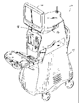
FIG. I is a perspective view of one embodiment of the surgical console of the
present invention.
FIG. 2 is an assembled view of the panel display articulation mechanism of the
io present invention.
FIG. 3 is an exploded, partial assembly view of the panel display articulation
mechanism of the present invention illustrating a first cable wrap mechanism.
FIG. 4 is an exploded, partially assembled view of the panel display
articulation
mechanism of the present invention illustrating the cable routing.
rs FIG. 5 is an exploded, partial assembly view of the panel display
articulation
mechanism of the present invention illustrating a second cable wrap mechanism.
FIG. 6 is an exploded, partially assembled view of the panel display
articulation
mechanism of the present invention illustrating the cable routing.
FIG. 7 is a perspective view of the assembled articulation mechanism of the
present
2o invention.
Detailed Description of the Invention
As best seen in FIG. l, surgical console 10 of the present invention generally
Zs includes panel display 12 mounted to body 14 of console 10 by articulation
mechanism 16.
As best seen in FIGS. 2-7, articulation mechanism 16 generally includes base
I8, upper
spindle assembly 20 having upper cable wrap 21, lower spindle assembly 23
having lower
cable wrap 22 and cable 24. Upper spindle assembly 20 may be of any suitable
design,
but generally includes shaft 19 along with a suitable drag brake (not shown.
fable 24
so preferably is of one continuous, uninterrupted length and has connectors 25
on either end
for connecting display 12 to console 10 through articulation mechanism 16.
As best seen in FIGS. 3 and 4, cable 24 wraps around helix upper cable wrap 21
in
upper spindle assembly 20 and is held in place by screws 26 and clamps 28 in
base 18.
2

CA 02434349 2003-07-04
Upper cable wrap 21 allows panel 12 spin on upper spindle assembly 20 without
straining
or damaging cable 24. Upper spindle assembly 20 allows panel display 12 to
spin about
spindle 19 through at least 90° of motion and preferably at least
225° of motion. Upper
spindle assembly 20 also contains pivot arms 30. As best seen in FIG. '7,
vertical
s mounting arms 32 are rotationally mounted on pivot arms 30 and contain
mounting holes
34 for allowing the mounting of panel display 12 on mounting arms 32. Mounting
arms
32 allow for tilting on panel display 12, such action being assisted by
springs 36 slidably
received on pivot arms 30. Springs 36 also have a gravity compensating
function,
preventing the weight of panel display I2 from rotating panel display 12
downward. In
io addition, pivot arms 30 may contain a suitable drag brake (not shown).
Preferably, pivot
arms 30 and mounting arms 32 allow enough range of motion so as to allow panel
display
12 to tilt forward and tilt backward to fold flat against base I8, preferably
at least 95° of
motion.
As best seen in FIGS. 5 and 6, Lower spindle assembly 23 contains spindle 38,
is clamping plate 40, screw 42 and lower cable wrap 22. Spindle 38 may be of
any suitable
design, but generally includes shaft 39, housing 41 and a suitable drag brake
(not shown).
Screw 42 is received through clamping plate 40, lower cable wrap 22, base 18
and into
spindle 38. Cable 24 is fix to clamping plate 40 by screws 44 and clamp 46.
Spindle 38
and lower cable wrap 22 operate within base 18 in the manner described above
to allow
Zo rotation (swivel) of Lower base 18 on console 10, preferably, through at
least 90° of motion
and more preferable, through at least 180° of motion.
In use, assembly 16 of the present invention allow panel display 12 to rotate
along
three axes, spin (about upper spindle assembly 20), tilt (about pivot arms 30)
and swivel
(about Lower spindle assembly 23). Upper cable wrap 21 and lower cable wrap 22
coil
zs cable 24 in a helix shape, allowing for rotation of upper spindle assembly
20 and lower
spindle assembly 23 without straining or damaging cable 24. Such a
construction also
allows the use of a continuous, uninterrupted sable 24, with no intermediate
breaks or
connections between console 10 and panel display I2, thereby simplifying
construction and
reducing unwanted electrical noise to panel display 12.
3o This description is given for purposes of illustration and explanation. It
will be
apparent to those skilled in the relevant art that modifications may be made
to the
invention as herein described without departing from its scope or spirit.
3

Representative Drawing
A single figure which represents the drawing illustrating the invention.
Administrative Status

2024-08-01:As part of the Next Generation Patents (NGP) transition, the Canadian Patents Database (CPD) now contains a more detailed Event History, which replicates the Event Log of our new back-office solution.

Please note that "Inactive:" events refers to events no longer in use in our new back-office solution.

For a clearer understanding of the status of the application/patent presented on this page, the site Disclaimer , as well as the definitions for Patent , Event History , Maintenance Fee  and Payment History  should be consulted.

Event History

Description Date
Inactive: Expired (new Act pat) 2023-07-04
Inactive: IPC deactivated 2021-10-09
Inactive: Recording certificate (Transfer) 2020-02-04
Common Representative Appointed 2020-02-04
Inactive: Multiple transfers 2019-12-18
Common Representative Appointed 2019-10-30
Inactive: IPC assigned 2019-05-24
Inactive: First IPC assigned 2019-05-24
Inactive: IPC assigned 2019-05-24
Change of Address or Method of Correspondence Request Received 2018-01-09
Inactive: IPC expired 2016-01-01
Grant by Issuance 2009-06-02
Inactive: Cover page published 2009-06-01
Inactive: Final fee received 2009-03-16
Pre-grant 2009-03-16
Letter Sent 2008-09-29
Notice of Allowance is Issued 2008-09-29
Inactive: IPC removed 2008-09-02
Amendment Received - Voluntary Amendment 2008-07-02
Inactive: Approved for allowance (AFA) 2008-06-30
Amendment Received - Voluntary Amendment 2008-03-12
Inactive: S.30(2) Rules - Examiner requisition 2008-01-15
Letter Sent 2006-08-29
Request for Examination Received 2006-08-03
Request for Examination Requirements Determined Compliant 2006-08-03
All Requirements for Examination Determined Compliant 2006-08-03
Amendment Received - Voluntary Amendment 2006-08-03
Inactive: IPC from MCD 2006-03-12
Application Published (Open to Public Inspection) 2004-03-05
Inactive: Cover page published 2004-03-04
Inactive: IPC assigned 2003-08-29
Inactive: First IPC assigned 2003-08-29
Application Received - Regular National 2003-08-14
Filing Requirements Determined Compliant 2003-08-14
Inactive: Filing certificate - No RFE (English) 2003-08-14
Letter Sent 2003-07-04

Abandonment History

There is no abandonment history.

Maintenance Fee

The last payment was received on 2008-06-19

Note : If the full payment has not been received on or before the date indicated, a further fee may be required which may be one of the following

  • the reinstatement fee;
  • the late payment fee; or
  • additional fee to reverse deemed expiry.

Please refer to the CIPO Patent Fees web page to see all current fee amounts.

Owners on Record

Note: Records showing the ownership history in alphabetical order.

Current Owners on Record
ALCON INC.
Past Owners on Record
ARGELIO M. OLIVERA
DOUGLAS T. PACKARD
Past Owners that do not appear in the "Owners on Record" listing will appear in other documentation within the application.
Documents

To view selected files, please enter reCAPTCHA code :


To view images, click a link in the Document Description column. To download the documents, select one or more checkboxes in the first column and then click the "Download Selected in PDF format (Zip Archive)" or the "Download Selected as Single PDF" button.

List of published and non-published patent-specific documents on the CPD .

If you have any difficulty accessing content, you can call the Client Service Centre at 1-866-997-1936 or send them an e-mail at CIPO Client Service Centre.


Document
Description 
Date
(yyyy-mm-dd) 
Number of pages   Size of Image (KB) 
Abstract 2003-07-04 1 14
Drawings 2003-07-04 7 217
Description 2003-07-04 3 203
Claims 2003-07-04 2 81
Representative drawing 2003-09-08 1 15
Cover Page 2004-02-06 1 39
Claims 2008-03-12 1 38
Representative drawing 2009-05-11 1 16
Cover Page 2009-05-11 2 44
Courtesy - Certificate of registration (related document(s)) 2003-07-04 1 106
Filing Certificate (English) 2003-08-14 1 160
Reminder of maintenance fee due 2005-03-07 1 111
Acknowledgement of Request for Examination 2006-08-29 1 177
Commissioner's Notice - Application Found Allowable 2008-09-29 1 163
Correspondence 2009-03-16 1 38