Note: Descriptions are shown in the official language in which they were submitted.
CA 02434733 2003-07-09
DESCRIPTION
APPARATUS AND METHOD FOR REMOVING FOREIGN OBJECT
TECHNICAL FIELD
The present invention relates to an apparatus and a method for
removing a foreign object or matter such as scale attached onto an inner
surface of a small bore pipe such as a heat transfer pipe or a heat exchanger
tube of a heat exchanger and an inner surface of a general pipe.
BACKGROUND ART
A heat exchanger is constituted, for example, in the following
manner: a large number of heat transfer pipes are arrayed within a housing
provided therein so as to be formed in a U shape, and are coupled to a lower
inlet collection pipe and a upper outlet collection pipe, respectively. An
inlet pipe is provided on an upper portion thereof to communicate or connect
with the housing, and an outlet pipe is provided on an upper sidewall
thereof to be coupled to an intermediate space thereof.
Hence, for example, if cooling water is supplied from the inlet
collection pipe into the large number of heat transfer pipes within the
housing while high-temperature air is supplied from the inlet pipe into the
housing, then the high-temperature air descends and the cooling water
ascends in the housing, and thus a heat exchange is performed. Then, the
cooled air reverses itself upward from the lower portion of the housing,
ascends through the intermediate space, and is discharged from the outlet
pipe. Meanwhile, the cooling water is discharged from the outlet collection
pipe.
In such a heat exchanger, it is necessary to perform an ECT
inspection for the heat transfer pipes periodically. However, because oxide
scale is generated on the inner surfaces of the heat transfer pipes due to
long-term use, it is necessary to remove this oxide scale before the
inspection. As a method for removing the oxide scale on the inner surfaces
of the heat transfer pipes, it is general to use a blast method in which an
abrasive is sent with pressure to the heat transfer pipes to abrade and
remove the scale. For example, this method is disclosed in Japanese
Patent Laid-Open Publication 2001-150348.
-1-
CA 02434733 2003-07-09
As described above, in the conventional oxide scale removing method,
the swirling flow of the abrasive is made to collide with the oxide scale
generated on the inner sui-faces of the steel pipes to perform blast
processing therefor, thus removing the oxide scale. The oxide scale can be
removed irrespective of the unevenness of the inner surfaces of the steel
pipes by allowing the abrasive to collide with the oxide scale as described
above on the inner surfaces of the steel pipes from various directions.
However, regarding a specific portion where a large amount of oxide scale is
generated, the removal of the oxide scale cannot be sufficient. In order to
remove the large amount of oxide scale generated on the inner surfaces of
the steel pipes, the amount of abrasive and a rate or speed at which the
abrasive is sent with pressure must be increased, causing problems that an
equipment for abrasion is to be larger and that costs become higher.
Moreover, due to restriction on the local thinning amount of the bent
portion of each U-shaped pipe, the increases in the abrasive amount and the
pressure rate at which the abrasive is sent with pressure may sometimes be
limited when the oxide scale is in a large amount. In this case, the oxide
scale is removed by a manual operation, causing a problem that it takes an
extremely long time to do the operation for the heat exchanger having no
less than several thousands of heat transfer pipes.
The present invention was made in order to solve such problems as
described above. It is an object of the present invention to provide an
apparatus and a method for removing a foreign object or matter, which are
capable of easy removal of the foreign object such as scale attached onto
inner surfaces of pipes of nuclear power equipment or the like for a short
period of time by means of simple equipment and manner.
DISCLOSURE OF THE INVENTION
An apparatus for removing a foreign object of a first aspect of the
present invention, which is for achieving the foregoing object, is
characterized by comprising: an abrasion assisting member with a diameter
smaller than an inner diameter of a pipe, the abrasion assisting member
being inserted into the pipe; a holder mechanism for holding the abrasion
assisting member, the holder mechanism being attachable to/detachable
from an end of the pipe; and blasting means for sending abrasive with
pressure into the pipe to remove the foreign object attached onto an inner
.2.
CA 02434733 2003-07-09
surface of the pipe. The abrasive may be sent with pressure from any of
the ends of the pipe: the end into which the abrasion assisting member is
inserted, and an end opposite thereto.
According to the apparatus for removing a foreign object of the first
aspect of the present invention, the foreign object or matter is removed by
increasing a flow rate of the abrasive between the inner surface of the pipe
and the abrasion assisting member, thus making it possible to abrade and
remove the foreign object or matter such as scale attached onto the inner
surface of the pipe easily for a short period of time by means of simple
equipment.
An apparatus for removing a foreign object of a second aspect of the
present invention is characterized in that, in the apparatus for removing a
foreign object of the first aspect of the present invention, a holder that is
attachable to/detachable from the end of the pipe and a support arm
supported in the holder to be freely movable in an axial direction thereof
and having a tip end freely insertable into/withdrawable from the pipe
through an opening of the pipe are included as the holder mechanism, and
the abrasion assisting member is attached onto the tip end of the support
arm.
According to the apparatus for removing a foreign object of the
second aspect of the present invention, the support arm is operated, thus
making it possible to remove the foreign object or matter such as scale
attached onto a desired area in the pipe.
An apparatus for removing a foreign object of a third aspect of the
present invention is characterized in that, in the apparatus for removing a
foreign object of the second aspect of the present invention, a centering
mechanism for centering the abrasion assisting member inside the pipe by
interposing the support arm therebetween is provided in the holder.
According to the apparatus for removing a foreign object of the third
aspect of the present invention, a space between the inner circumference of
the pipe and the abrasion assisting member is equalized in a circumferential
direction, thus making it possible to remove the foreign object or matter
attached onto the inner surface of the pipe appropriately.
An apparatus for removing a foreign object of a fourth aspect of the
present invention is characterized in that, in the apparatus for removing a
foreign object of the second aspect of the present invention, a clamping
-3-
CA 02434733 2003-07-09
member brought into contact with an inner circumferential surface of the
pipe for preventing vibrations is provided on the tip end of the abrasion
assisting member.
According to the apparatus for removing a foreign object of the
fourth aspect of the present invention, the space between the inner surface
of the pipe and the abrasion assisting member is maintained at a
predetermined interval, thus making it possible to remove the foreign object
or matter attached onto the inner surface of the pipe appropriately.
An apparatus for removing a foreign object of a fifth aspect of the
present invention is characterized in that, in the apparatus for removing a
foreign object of the second aspect of the present invention, a spiral groove
is
formed on an outer circumferential surface of the abrasion assisting member.
According to the apparatus for removing a foreign object of the fifth
aspect of the present invention, a swirling flow of the abrasive is formed
between the inner surface of the pipe and the abrasion assisting member,
thus making it possible to remove the foreign object or matter attached onto
the inner surface of the pipe securely.
An apparatus for removing a foreign object of a sixth aspect of the
present invention is characterized in that, in the apparatus for removing a
foreign object of the first aspect of the present invention, a tapered portion
with an outer diameter thinned downstream of the pipe is provided on the
abrasion assisting member.
According to the apparatus for removing a foreign object of the sixth
aspect of the present invention, an amount of decompression/expansion by a
pressure drop due to a pressure loss is compensated, and a flow rate of the
abrasive is made constant, thus making it possible to remove the foreign
object attached onto the inner surface of the pipe evenly.
An apparatus for removing a foreign object of a seventh aspect of the
present invention is characterized in that, in the apparatus for removing a
foreign object of the first aspect of the present invention, a blast path open
from the downstream of the abrasive flow, passing through an inside of the
abrasion assisting member to an outer circumference thereof is provided in
the abrasion assisting member, and second blasting means for sending the
abrasive with pressure into the blast path in a reverse direction to a flowing
direction of the abrasive in the pipe is included. In this case, the second
blasting ineans may also be commonly used as the blasting means in the
- n -
CA 02434733 2003-07-09
apparatus for removing a foreign object of the first aspect of the present
invention.
According to the apparatus for removing a foreign object of the
seventh aspect of the present invention, an injection of the abrasive from the
outer circumference of the abrasion assisting member and a flow of the
abrasive in the pipe synergize to increase the total amount of abrasive, and
the flow rate of the abrasive on the outer circumference of the abrasion
assisting member is further increased by the injection of the abrasive from
the outer circumference of the abrasion assisting member, thus making it
possible to remove the foreign object or matter attached onto the inner
surface of the pipe more effectively.
An apparatus for removing a foreign object of an eighth aspect of the
present invention is characterized in that, in the apparatus for removing a
foreign object of the seventh aspect of the present invention, the blasting
means sends the abrasive with pressure into the pipe from one end of the
pipe, and the second blasting means sends the abrasive with pressure into
the blast path of the abrasion assisting member from the other end of the
pipe.
According to the apparatus for removing a foreign object of the
eighth aspect of the present invention, the abrasive can be sent with
pressure into the blast path of the abrasion assisting member easily in a
reverse direction to the flowing direction of the abrasive in the pipe.
An apparatus for removing a foreign object of a ninth aspect of the
present invention is characterized in that, the apparatus for removing a
foreign object of the seventh aspect of the present invention comprises: a
holder that is attachable to/detachable from the end of the pipe; a support
arm supported in the holder to be freely movable in an axial direction
thereof and having a tip end freely insertable into/withdrawable from the
pipe through an opening of the pipe, as well as the abrasion assisting
member attached to the tip end of the arm; and connecting means for
connecting the blast path of the abrasion assisting member to the second
blasting means, the connecting means being capable of absorbing a distance
change between the abrasion assisting member and the second blasting
means. As the connecting means, a flexible hose and a telescopic pipe can
be used.
According to the apparatus for removing a foreign object of the ninth
.,.
CA 02434733 2003-07-09
aspect of the present invention, the support arm is operated, thus making it
possible to remove the foreign object or matter attached onto the desired
area in the pipe.
An apparatus for removing a foreign object of a tenth aspect of the
present invention is characterized in that, in the apparatus for removing a
foreign object of the first aspect of the present invention, a spiral groove
is
provided on the abrasion assisting member.
According to the apparatus for removing a foreign object of the tenth
aspect of the present invention, a swirling flow of the abrasive is generated
between the inner surface of the pipe and the outer surface of the abrasion
assisting member, thus increasing centrifugal force of the abrasive to
enhance the abrasion effect, and making it possible to abrade the abrade
surface, that is, the inner surface of the pipe smoothly.
A method for removing a foreign object of an eleventh aspect of the
present invention, which is for achieving the foregoing object, is
characterized by comprising the steps of= inserting, into a pipe, an abrasion
assisting member with a diameter smaller than an inner diameter of the
pipe; sending abrasive with pressure into the pipe; increasing a flow rate of
the abrasive in a space between an inner surface of the pipe and the
abrasion assisting member; and removing a foreign object attached onto the
inner surface of the pipe.
According to the method for removing a foreign object of the eleventh
aspect of the present invention, the foreign object or matter such as scale
attached onto the inner surface of the pipe can be removed easily for a short
period of time in a simple manner.
A method for removing a foreign object of a twelfth aspect of the
present invention is characterized in that, in the method for removing a
foreign object of the eleventh aspect of the present invention, the abrasion
assisting member is inserted into the pipe by interposing a support arm
therebetween, and the abrasion assisting member is centered and held at a
position facing to the foreign object.
According to the method for removing a foreign object of the twelfth
aspect of the present invention, a space between the inner surface of the
pipe and the abrasion assisting member is equalized in the circumferential
direction, thus making it possible to remove the foreign object or matter
attached onto the inner surface of the pipe appropriately.
- G -
CA 02434733 2003-07-09
A method for removing a foreign object of a thirteenth aspect of the
present invention is characterized in that, in the method for removing a
foreign object of the eleventh aspect of the present invention, the abrasive
is
sent with pressure into an inside of the abrasion assisting member in a
reverse direction to a flowing direction of the abrasive in the pipe, and the
abrasive is-injected from an inside of the abrasion assisting member to an
outer circumference thereof.
According to the method for removing a foreign object of the
thirteenth aspect of the present invention, an injection of the abrasive from
the outer circumference of the abrasion assisting member and a flow of the
abrasive in the pipe synergize to increase the total amount of abrasive, and
the flow rate of the abrasive on the outer circumference of the abrasion
assisting member is further increased by the injection of the abrasive from
the outer circumference of the abrasion assisting member, thus making it
possible to remove the foreign object or matter attached onto the inner
surface of the pipe more effectively.
A method for removing a foreign object of a fourteenth aspect of the
present invention is characterized in that, in the method for removing a
foreign object of the eleventh aspect of the present invention, the flow rate
of
the abrasive is made constant by a tapered portion with an outer diameter
thinned downstream of the pipe, the tapered portion being formed on the
abrasion assisting member.
According to the method for removing a foreign object of the
fourteenth aspect of the present invention, the foreign object or matter
attached onto the inner surface of the pipe can be removed evenly.
A method for removing a foreign object of a fifteenth aspect of the
present invention is characterized in that, in the method for removing a
foreign object of the eleventh aspect of the present invention, centrifugal
force of the abrasive is increased by a spiral groove formed on the abrasion
assisting member.
According to the method for removing a foreign object of the fifteenth
aspect of the present invention, a swirling flow of the abrasive is generated
between the inner surface of the pipe and the outer surface of the abrasion
assisting member, thus increasing centrifugal force of the abrasive to
enhance the abrasion effect, and making it possible to abrade the abraded
surface, that is, the inner surface of the pipe smoothly.
-7-
CA 02434733 2003-07-09
BRIEF DESCRIPTION OF THE DRAWINGS
FIG. 1 is a schematic cross-sectional view of a foreign object
removing apparatus according to a first embodiment of the present
invention.
FIG. 2 is a cross-sectional view taken along the plane II-II of FIG. 1.
FIG. 3 is a cross-sectional view taken along the plane III-III of FIG.
1.
FIG. 4 is a view illustrating an abrasion assisting member having a
tapered portion.
FIG. 5 is a schematic cross-sectional view of a foreign object
removing apparatus according to a second embodiment of the present
invention.
FIG. 6 is a schematic cross-sectional view of a foreign object
removing apparatus according to a third embodiment of the present
invention.
FIG. 7 is a view illustrating an abrasion assisting member having a
tapered portion.
FIG. 8 is a graph showing a relationship between an abrasion rate or
speed in an abrasion assisting member with a constant outer diameter and
a position thereof in an area where scale is abraded.
FIG. 9 is a graph showing a relationship between an abrasion rate or
speed in an abrasion assisting member having a tapered portion and a
position thereof in an area where scale is abraded.
FIG. 10 is a schematic cross-sectional view of a foreign object
removing apparatus constituted to commonly use one blast device for
sending an abrasive with pressure to a pipe and sending an abrasive with
pressure to a blast path of the abrasion assisting member.
FIG. 11 is a view illustrating another connection example of the
blast device and the blast path of the abrasion assisting member.
BEST MODE FOR CARRYING OUT THE INVENTION
Embodiments of the present invention will be described below in
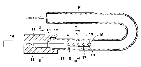
detail based on the drawings. In the drawings, a reference symbol P
denotes a pipe; a reference symbol S denotes oxide scale (foreign object or
matter); a reference symbol A denotes a scale-abraded area; reference
.g.
CA 02434733 2003-07-09
numerals 11 and lla denote holders; reference numerals 12 and 12a denote
engaging portions; reference numerals 13 and 13a denote blast paths of the
holders; reference numerals 14 and 14a denote blast devices (blasting
means); a reference numeral 15 denotes a support arm; a reference numeral
16 denotes an abrasion assisting member; a reference numeral 17 denotes a
spiral groove; a reference numeral 18 denotes guide protrusions (centering
mechanism); a reference numeral 19 denotes support protrusions (clamping
member); a reference numeral 20 denotes a tapered portion of the abrasion
assisting member (downstream side); a reference numeral 21 denotes a
tapered portion of the abrasion assisting member (upstream side); a
reference numeral 22 denotes a blast path of the abrasion assisting member;
a reference numeral 23 denotes outer circumferential openings of the
abrasion assisting member; a reference numeral 24 denotes a blast path
(connecting means) of the support arm; a reference numeral 27 denotes a
valve; and a reference numeral 28 denotes a flexible hose (connecting
means).
<First embodiment>
FIG. 1 is a view schematically illustrating a foreign object removing
apparatus according to a first embodiment of the present invention, FIG. 2
shows a cross-section taken along the plane II-II of FIG. 1, and FIG. 3 shows
a cross-section taken along the plane III-III of FIG. 1.
As illustrated in FIGS. 1 to 3, the foreign object removing apparatus
of this first embodiment is one for use, for example, in the case of abrading
the scale S as a foreign object generated in the pipe P used as a heat
transfer pipe or the like of a heat exchanger for atomic equipment.
Particularly, a large amount of the scale S is generated in the area A in the
vicinity of the opening of the pipe P.
For example, when a pipe plate is made of SUS304 and a heat
transfer pipe is made of a copper-nickel alloy, for example, a large amount of
layer having a thickness of 70 to 100 m, from which nickel is desorbed, is
generated in an area where the pipe plate and the outlet portion of the heat
transfer pipe are connected to each other. This layer becomes a cause of
noise in an ECT inspection, and may sometimes inhibit detection of
corrosion between the pipe plate and the heat transfer pipe. Incidentally,
in the portion other than the above-described area, the thickness of the
layer is 2 to 3 m. As such, the amount of scale is varied to a large extent.
-~-
CA 02434733 2003-07-09
In this foreign object removing apparatus, as a holder mechanism for
holding the abrasion assisting member 16, the holder 11, the support arm 15
and the centering mechanism 18 are provided. The holder 11 has the
engaging portion 12 freely attachable to/detachable from the opening end of
the pipe P. In the inside of the holder 11, the blast path 13 forming a
circular cross=section is formed. The blast path 13 is different from the
blast path 22 inside the abrasion assisting member 16 to be described later
with reference to FIG. G. Then, to the blast path 13 of this holder 11, the
blast device 14 is connected, which abrades and removes the scale S
attached onto the inner surface of the pipe P by sending an abrasive (for
example, fine particles of alumina) into the pipe P by means of compressed
air.
The support arm 15 is supported in the blast path 13 of the holder 11
to be freely movable in an axial direction thereof. The support arm 15 has
an unillustrated operation unit operatable by an operator on a base end
thereof, and a tip end thereof is freely insertable into/withdrawable from the
inside of the pipe P through the opening end of the pipe P. The abrasion
assisting member 16 is fixed to this tip end.
This abrasion assisting member 16 is formed in a cylindrical shape
with a diameter smaller than the inner diameter of the pipe P, and on an
outer circumferential surface thereof, the spiral groove 17 is formed. The
spiral groove 17 generates a swirling flow of the abrasive between the inner
surface of the pipe P and the outer surface of the abrasion assisting member
16.
Moreover, the three guide protrusions 18 as a centering mechanism
for centering the abrasion assisting member 16 in the pipe P are fitted onto
the intermediate portion of the support arm 15. Each of these guide
protrusions 18 has an equal length to one another, and is fitted onto the
support arm 15 in a circumferential direction at an approximately equal
interval. The tip end of each guide protrusion 18 is engaged with the inner
wall surface of the blast path 13 to be freely slidable. Hence, the holder 11
is engaged with the pipe P by the engaging portion 12 so that the axial
centers of the blast path 13 and the pipe P can coincide with each other, and
the support arm 15 is centered by the guide protrusions 18 in the blast path
13, thus making it possible to center the abrasion resistant member 16 in
the pipe P.
].0-
CA 02434733 2003-07-09
Furthermore, onto the tip end of the abrasion assisting member 16,
the three support protrusions 19 are fitted as clamping members for holding
the abrasion assisting member 16 so that the member 16 does not vibrate in
the pipe P. Each of these support protrusions 19 has an equal length to one
another, and is fitted onto the abrasion assisting member 16 in a
circumferential direction at an approximately equal interval. The tip end
of each support protrusion 19 is freely slidable on the inner circumferential
surface of the pipe P. Hence, the abrasion assisting member 16 centered in
the pipe P by the guide protrusions 18 with the support arm 15 interposed
therebetween is appropriately supported by the support protrusions 19
without any vibrations. The abrasion assisting member 16 is also centered
by the support protrusions 19.
Here, descriptions will be made for work of removing the oxide scale
S generated on the inner surface of the pipe P by means of the foreign object
removing apparatus of the first embodiment, which is constituted as
described above. In this case, it is inspected beforehand in which position
of the pipe P the oxide scale S is generated in a large amount so that a scale-
abraded area is preset. In this first embodiment, this area is set in the
area A in the vicinity of the opening of the pipe P.
First, the engaging portion 12 is engaged with the opening end of the
pipe P, and thus the holder 11 is attached onto the pipe P. Then, the blast
device 14 is connected to the blast path 13 of the holder 11. Next, the
abrasion assisting member 16 is inserted into the pipe P by the support arm
15 and is stopped at the scale-abraded area A where the oxide scale S is
generated in a large amount. At this point, the abrasion assisting member
16 is centered by the guide protrusions 18 with the support arm 15
interposed therebetween. Thus, a distance between the inner surface of
the pipe P and the outer surface of the abrasion assisting member 16
becomes substantially equal in the circumferential direction.
In this state, an abrasive is sent into the pipe P through the blast
path 13 by compressed air by means of the blast device 14. Then, because
the abrasion assisting member 16 is located in the scale-abraded area A in
the pipe P, a flow passage for the abrasive in this scale-abraded area A is
narrowed as compared with those in areas therebefore and thereafter, and
the flow speed or rate of the abrasive is increased. Therefore, more
abrasive will collide with the oxide scale S generated on the inner surface of
~1-
CA 02434733 2003-07-09
the pipe P at a higher rate, and an abrasion effect is enhanced in proportion
to the square of the flow rate, thus making it possible to abrade and remove
the large amount of oxide scale S easily and securely.
Moreover, the spiral groove 17 is formed on the outer circumferential
surface of the abrasion assisting member 16, and therefore, the swirling
flow of the abrasive will be generated and held between the inner surface of
the pipe P and the outer surface of the abrasion assisting member 16.
Accordingly, the centrifugal force of the abrasive is increased to enhance the
abrasion effect, and the abraded surface, that is, the inner surface of the
pipe P can be abraded smoothly. Furthermore, the tip end (downstream
portion) of the abrasion assisting member 16 is supported to be clamped by
the support protrusions 19, and the abrasion assisting member 16 does not
vibrate due to the swirling flow and the like, thus making it possible to
perform appropriate abrading work. Moreover, the front and rear ends of
the abrasion assisting member 16 are spherical, and the swirling flow will
be straightened downstream of this abrasion assisting member 16 to be
flown smoothly without generating turbulence.
As described above, in the foreign object removing apparatus of this
first embodiment, the holder 11 is attached onto the end of the pipe P, and
the abrasion assisting member 16 fixed to the tip end of the support arm 15
is inserted into the pipe P by use of the holder 11 and stopped at the scale-
abraded area A where the oxide scale S is generated in a large amount, thus
being adapted to send the abrasive with pressure into the pipe P by means
of the blast device 14.
Hence, the flow passage of the abrasive is narrowed to increase the
flow rate in the scale-abraded area A where the abrasion assisting member
16 is located, and therefore, much abrasive will collide with the oxide scale
S
generated on the inner surface of the pipe P at a higher rate, thus making it
possible to abrade and remove this oxide scale S easily and securely for a
short period of time.
In the above-described embodiment, the pipe is formed into a hollow
cylinder shape, and the abrasion assisting member 16 is formed into a solid
cylinder shape. However, the abrasion assisting member 16 may be formed
in a solid prism shape if the pipe is formed in a hollow prism shape.
Moreover, the numbers and shapes of the guide protrusions 18 as the
centering mechanism and of the support protrusions 19 as the clamping
- 12?
CA 02434733 2003-07-09
members are not limited to those of this embodiment.
Moreover, in the above-described first embodiment, the abrasion
assisting member 16 is set to have a constant diameter except the spherical
front and rear ends thereof. However, as the tapered portion 20 illustrated
in FIG. 4, almost all portions of the abrasion assisting member 16 may be
formed in a tapered shape in which an outer diameter is thinned or
decreased downstream of the pipe. This tapered portion 20 compensates an
amount of decompression/expansion by a pressure drop due to a pressure
loss, and makes the flow rate of the abrasive more constant than in the case
where the tapered portion 20 is not provided. Therefore, the scale-abraded
area A can be abraded evenly. The extent of the tapered shape can be set
appropriately by, for example, experiments and the like. Reversely to this,
the portion 21 that is upstream of the downstream tapered portion 20 is
formed in a tapered shape in which an outer diameter is thinned toward the
upstream so as to reduce resistance. Moreover, the downstream tapered
portion 20 and the upstream tapered portion 21 will straighten the swirling
flow downstream of the abrasion assisting member 16, and the swirling flow
is flown smoothly without generating turbulence or the like.
Moreover, although the support arm 15 is supported to be freely
movable in the axial direction in the blast path 13 of the holder 11, it is
not
necessary that the support arm 15 be freely movable when the scale-
abraded area A is fixedly determined, then a support arm 15 in which a
length is preset in accordance with the scale-abraded area A can be used
when the scale-abraded area A is fixedly determined.
<Second embodiment>
Next, FIG. 5 schematica.lly illustrates a foreign object removing
apparatus according to a second embodiment of the present invention. In
the above-described first embodiment, the abrasion assisting member 16 is
inserted and the abrasive is sent with pressure from the same end. However,
in this second embodiment, as illustrated in FIG. 5, the insertion and the
sending are performed from ends opposite to each other.
Similarly to the apparatus illustrated in FIG. 1, the foreign object
removing apparatus of this second embodiment is one used in the case of
abrading the scale S as a foreign object generated in the pipe P used as the
heat transfer pipe or the like of the heat exchanger.
Specifically, as illustrated in FIG. 5, in the foreign object removing
=13
CA 02434733 2003-07-09
apparatus of this second embodiment, the holder 11, which has the blast
path 13 with a circular cross-section in the inside thereof and the engaging
portion 12, is attached to be freely attachable to/detachable from one
opening end of the pipe P, similarly to FIG. 1. Moreover, another holder
lla is attached freely detachably onto another opening end of the pipe P.
This holder lia also has the - engaging portion 12a freely attachable
to/detachable from the opening end of the pipe P, and in the inside thereof, a
blast path 13a forming a circular cross-section is formed. Then, to the blast
path 13a of this holder lla, the blast device 14 is connected, which abrades
and removes the scale S attached onto the inner surface of the pipe P by
sending the abrasive with pressure into the pipe P by means of compressed
air.
Moreover, in the holder 11, similarly to FIG. 1, the support arm 15 is
supported in the blast path 13 so as to be freely movable in the axial
direction. This support arm 15 has an unillustrated operation unit by an
operator on a base end thereof, and a tip end that is freely insertable
to/withdrawable from inside of the pipe P through the opening end of the
pipe P. The abrasion assisting member 16 is fixed to this tip end.
In this second embodiment, the abrasion assisting member 16 has a
smaller diameter than the inner diameter of the pipe P, and on the outer
circumferential surface thereof, the spiral groove 17 is formed. With regard
to the shape of the abrasion assisting member 16, similarly to the one
illustrated in FIG. 4, almost all portions are formed in a tapered shape, in
which an outer diameter is thinned downstream of the pipe, so that the flow
rate of the abrasive can be made constant and the scale-abraded area A can
be abraded evenly. Reversely to this, the portion 21 in the upstream of this
tapered portion 20 is formed in a tapered shape in which an outer diameter
is thinned toward the upstream so as to reduce resistance. Similarly to the
one in FIG. 1, the spiral groove 17 is formed also on the outer circumference
of this abrasion assisting member 16, if required.
Moreover, similarly to FIG. 1, the three guide protrusions 18 as a
centering mechanism are fitted onto the intermediate portion of the support
arm 15, and the three support protrusions 19 as clamping members are
fitted onto the tip end of the abrasion assisting member 16.
In the case of removing the foreign object by use of the foreign object
removing apparatus of this second embodiment, first, the engaging portion
- 14 -
CA 02434733 2003-07-09
12 is engaged with the one opening end of the pipe P to be attached onto the
holder 11, the abrasion assisting member 16 is inserted into the pipe P by
the support arm 15 and stopped at the scale-abraded area A where the oxide
scale S is generated in a large amount. Moreover, the engaging portion 12a
is engaged with the other opening end of the pipe P to be attached onto the
holder lla, and the blast device 14 is connected to the blast path 13a of the
holder lla. In this state, the abrasive is sent with pressure through the
blast path 13a into the pipe P by the blast device 14 by means of compressed
air. Consequently, an operational advantage similar to that described with
reference to FIGS. 1 and 4 is obtained.
<Third embodiment>
Next, FIG. 6 schematically illustrates a foreign object removing
apparatus according to a third embodiment of the present invention. The
foreign object removing apparatus of this third embodiment is also one used
in the case of abrading the scale S as a foreign object generated in the pipe
P
used as a heat transfer pipe or the like of the heat exchanger, similarly to
the one illustrated in FIG. 1.
In this third embodiment, as illustrated in FIG. 6, the abrasive is
sent with pressure from a blast device 14a into the pipe P. In addition to
this, the abrasive is also sent with pressure from another blast device 14
into the inside of the abrasion assisting member 16 in a reverse direction to
the flowing direction of the abrasive in the pipe P. Thus, the abrasive is
injected from the inside toward the circumference of the abrasion assisting
member 16.
In this foreign object removing apparatus, as a holder mechanism for
holding the abrasion assisting member 16, the holder 11, the support arm 15
and the centering mechanism 18 are provided similarly to that of FIG. 1.
The holder 11 has the engaging portion 12 freely attachable to/detachable
from one opening end of the pipe P, and in the inside thereof, the blast path
13 forming a circular cross-section is formed. However, the blast device 14
is connected so as to send the abrasive with pressure not into the blast path
13 of the holder 11 but into the blast path 22 inside the abrasion assisting
member 16, though described later in detail. Then, in order to send the
abrasive with pressure into the pipe P, another holder lla and another blast
device 14a are provided. The holder Ila has the engaging portion 12a
freely attachable to/detachable from the other opening end of the pipe P, and
15-
CA 02434733 2003-07-09
in the inside thereof, the blast path 13a forming a circular cross-section is
formed. Another blast device 14a is connected to this blast path 13a of the
holder lla. Any of the blast devices 14 and 14a is one for abrading and
removing the scale S attached onto the inner surface of the pipe P by
sending the abrasive such as fine particles of alumina with pressure by
means of compressed air.
Similarly to that of FIG. 1, the support arm 15 is supported in the
blast path 13 of the holder 11 to be freely movable in the axial direction.
The support arm 15 has an unillustrated operation unit operatable by an
operator on the base end, and the tip end is freely insertable
into/withdrawable from the inside of the pipe P through the opening end of
the pipe P. The abrasion assisting member 16 is fixed to this tip end.
The abrasion assisting member 16 is formed in a cylindrical shape
with a diameter smaller than the inner diameter of the pipe P, and on the
outer circumferential surface, the spiral groove 17 is formed.
Moreover, in this abrasion assisting member 16, there is provided
the blast path 22 that is open from the downstream of the abrasive flow,
passing through the inside of the abrasion assisting member 16 to the outer
circumference thereof with respect to the flowing direction of the abrasive in
the pipe P that is sent with pressure from the blast device 14a. The
openings 23 on the circumference are located as upstream as possible and
provided in plural at an approximately equal interval in the circumferential
direction.
Furthermore, the three guide protrusions 18 as a centering
mechanism for centering the abrasion assisting member 16 in the pipe P are
fitted onto the intermediate portion of the support arm 15 similarly to those
of FIG. 1. Each of these guide protrusions 18 has an equal length to one
another, and is fitted onto the support arm 15 in the circumferential
direction at an approximately equal intexval. The tip end of each guide
protrusion 18 is engaged with the inner wall surface of the blast path 13 to
be freely slidable. Hence, the holder 11 is engaged with the pipe P so that
the axial centers of the blast path 13 and the pipe P can coincide with each
other, and the support arm 15 is centered by the guide protrusions 18 in the
blast path 13, thus making it possible to center the abrasion resistant
member 16 in the pipe P.
Moreover, in the inside of the support arm 15, the blast path 24
- ]G-
CA 02434733 2003-07-09
communicating or connecting with the blast path 22 of the abrasion
assisting member 16 is made open, and the blast device 14 is connected to
the blast path 24 of this support arm 15.
Moreover, onto the tip end of the abrasion assisting member 16
(upstream end with respect to the flowing direction of the abrasive in the
pipe P), the three support protrusions 19 are fitted as clamping members for
holding this abrasion assisting member 16 so that this member 16 does not
vibrate in the pipe P. Each of these support protrusions 19 has an equal
length to one another, and is fitted onto the abrasion assisting member 16 in
the circumferential direction at an approximately equal interval. The tip
end of each support protrusion 19 is freely slidable on the inner
circumferential surface of the pipe P. Hence, the abrasion assisting
member 16 centered in the pipe P by the guide protrusions 18 with the
support arm 15 interposed therebetween is appropriately supported by the
support protrusions 19 without any vibrations. The abrasion assisting
member 16 is also centered by the support protrusions 19.
Here, descriptions will be made for work of removing the oxide scale
S generated on the inner surface of the pipe P by means of the foreign object
removing apparatus of this embodiment, which is constituted as described
above. In this case, it is inspected beforehand in which position of the pipe
P the oxide scale S is generated in a large amount so that a scale-abraded
area is preset. In this embodiment, this area is set in the area A in the
vicinity of the outlet opening of the pipe P.
First, the engaging portion 12 is engaged with the one opening end
of the pipe P, and thus the holder 11 is attached onto the pipe P. Then, the
blast device 14 is connected to the blast path 22 of the abrasion assisting
member 16 by interposing the blast path 24 of the support arm 15
therebetween. Moreover, the engaging portion 12a is engaged with the
other opening end of the pipe P, and thus the holder lla is attached onto the
pipe P. Then, the blast device 14a is connected to the blast path 13a of the
holder lla. Next, the abrasion assisting member 16 is inserted into the
pipe P by the support arm 15 and is stopped at the scale-abraded area A
where the oxide scale S is generated in a large amount. At this point, the
abrasion assisting member 16 is centered by the guide protrusions 18 with
the support arm 15 interposed therebetween. Thus, a distance between the
inner surface of the pipe P and the outer surface of the abrasion assisting
-17-
CA 02434733 2003-07-09
member 16 becomes substantially equal in the circumferential direction.
In this state, the abrasive is sent with pressure into the blast path
22 of the abrasion assisting member 16 by compressed air by means of the
blast device 14 and directly injected from the outer circumferential openings
23 to the pipe P. Moreover, the abrasive is sent with pressure through the
blast path 13a into the pipe P by compressed air by means of the blast
device 14a.
Then, because the abrasion assisting member 16 is located in the
scale-abraded area A in the pipe P, the flow passage for the abrasive in this
scale-abraded area A is narrowed as compared with those in areas
therebefore and thereafter, and the flow rate or speed of the abrasive sent
with pressure from the blast device 14a is increased. In addition to this,
the abrasive sent with pressure from the blast device 14 is directly injected
from the outer circumferential openings 23 of the abrasion assisting
member 16, joined to the abrasive from the blast device 14a, and flown to
the one end of the pipe P. Therefore, as a synergistic effect of these, the
total amount of abrasive is increased. In addition, the flow rate or speed of
the abrasive on the outer circumference of the abrasion assisting member 16
is further enhanced due to the injection of the abrasion from the outer
circumferential openings 23 of the abrasion assisting member 16.
Therefore, more abrasive will collide with the oxide scale S generated on the
inner sui-face of the pipe P at a higher rate, and an abrasion effect
(abrasion
force) is enhanced, thus making it possible to abrade and remove the large
amount of oxide scale S easily and securely.
In this case, the blast device 14a sends the abrasive with pressure
from the other opening end of the pipe P into the pipe P, and the blast device
14 sends the abrasive with pressure from the one end of the pipe P into the
blast path 22 of the abrasion assisting member 16. Therefore, the abrasion
sending direction in the blast path 22 of the abrasion assisting member 16
can be easily reversed from the flowing direction of the abrasive in the pipe
P. Moreover, because the blast device 14 and the blast device 14a exist, the
amount of abrasive and the flow rate at which the abrasive is sent with
pressure by the blast device 14 and the amount of abrasive and the flow rate
at which the abrasive is sent with pressure by the blast device 14a can be
adjusted in accordance with a situation where the scale is attached onto the
pipe P. For example, in the case of abrading the vicinity of the outlet
- l.8 -
CA 02434733 2003-07-09
opening of the U shaped tube or pipe of the heat exchanger, the increases in
the abrasive amount from the blast device 14a and the flow rate at which
the abrasive is sent with pressure therefrom are restricted to the limitations
due to the restriction on the local thinning amount of the bent portion of the
U shape pipe. Instead, the amount of abrasive from the blast device 14 and
the flow rate at which the abrasive is sent with pressure therefrom are
greatly increased, thus securing the amount of abrasion and the flow rate of
abrasive, which are required in the scale-abraded area A, as a whole. Thus,
the large amount of scale S can be abraded in the scale-abraded area A
while inhibiting abnormal thinning.
Operational advantages (generation of the swirling flow of the
abrasive, an increase in the centrifugal force of the abrasive, improvement
of the abrasion effect, and smooth abrasion) due to the spiral groove 17
formed on the outer circumferential surface of the abrasion assisting
member 16, operational advantages (vibration prevention of the abrasion
assisting member 16 due to the swirling flow and the like, and appropriate
abrasion) due to the support protrusions 19 on the tip end of the abrasion
assisting member 16, and so on are similar to those described with reference
to FIG. 1.
Moreover, in the place where the amount of the scale attached is
locally large, such as the scale-abraded area A, the bore of the blast path 22
of the abrasion assisting member 16, the bore and number of the outer
circumferential openings 23 thereof and the bore of the blast path 24 of the
support arm 15 are changed in accordance with the amount of scale
attached, thus making it possible to control the flow rate on the outer
circumference of the abrasion assisting member 16, leading to the
improvement of the scale abrasion.
As described above, in the foreign object removing apparatus of this
third embodiment, the holder lla is attached onto the other end of the pipe
P, and the abrasive is sent with pressure from the blast path 13a of this
holder lla into the pipe P by use of blast device 14a. In addition to this,
the holder 11 is attached onto the one end of the pipe P, and the abrasion
assisting member 16 fixed to the tip end of the support arm 15 is inserted
into the pipe P by use of this holder 11 and stopped at the area A where the
oxide scale S is generated in a large amount. Then, the abrasive is sent
with pressure into the blast path 22 in the inside of the abrasion assisting
19-
CA 02434733 2003-07-09
member 16 by the blast device 14 in the reverse direction to the flowing
direction of the abrasive from the blast device 14a. Thus, the abrasive is
injected from the inside to the outer circumference of the abrasion assisting
member 16.
Hence, in the scale-abraded area A where the abrasion assisting
member 16 is located, the flow of the abrasive from the blast device 14a and
the direct injection of the abrasive from the outer circumference of the
abrasion assisting member 16 synergize to increase the total amount of
abrasive. In addition, due to the injection of the abrasive from the outer
circumference of the abrasion assisting member 16, the flow rate of the
abrasive on the outer circumference of the abrasion assisting member 16 is
further increased. Therefore, more abrasive will collide with the oxide
scale S generated on the inner surface of the pipe P at a higher rate, thus
making it possible to abrade and remove this oxide scale S easily and
securely for a short period of time.
In the above-described third embodiment, both ends ( front end and
rear end) of the abrasion assisting member 16 may be formed to be spherical
similarly to those illustrated in FIG. 1. Moreover, the pipe P is formed into
the hollow cylindrical shape, and the abrasion assisting member 16 is
formed into the solid cylindrical shape. However, if the pipe is formed into
the hollow prism shape, then the abrasion assisting member 16 may be
formed into the solid prism shape. Moreover, the numbers and shapes of
the guide protrusions 18 as a centering mechanism and of the support
protrusions 19 as clamping members are not limited to those of this
embodiment.
Moreover, although the shape of the abrasion assisting member 16 is
made in a constant outer diameter in the above-described third embodiment,
almost all portions thereof may be formed in a tapered shape in which an
outer diameter is thinned downstream of the pipe as illustrated in FIG. 7.
This tapered portion 20 shown in FIG.7 compensates an amount of
decompression/expansion by a pressure drop, and makes the flow rate of the
abrasive more constant than in the case where the tapered portion 20 is not
provided. Therefore, the scale-abraded area A can be abraded evenly. The
extent of the tapered shape can be set appropriately by, for example,
experiments and the like. Reversely to this, the portion 21 in the upstream
of this downstream tapered portion 20 is formed in a tapered shape in which
-20
CA 02434733 2003-07-09
an outer diameter is thinned toward the upstream so as to reduce resistance.
The spiral groove 17 is formed also on the outer circumference of this
abrasion assisting member 16 as required, similarly to the one in FIG. 1.
In FIG. 7, a reference numeral 22 denotes the blast path, and a reference
numeral 23 denotes the outer circumferential openings. The outer
circumferential openings 23 may exist in the downstream tapered portion 20.
FIG. 8 exemplifies the relationship 25 between the abrasion rate or
cutting rate or grinding rate in use of the abrasion assisting member with a
constant outer diameter (FIG. 6) and the position thereof in the scale-
abraded area A. FIG. 9 exemplifies the relationship 26 between the
abrasion rate or cutting rate or grinding rate in use of the abrasion
assisting
member having the tapered portion 20 (FIG. 7) and the position thereof in
the scale-abraded area A. Because the flow rate is equalized in the case
where the tapered portion 20 is provided, it is understood from FIGS. 8 and
9 that the abrasion rate is equalized more in the case where the tapered
portion 20 is provided (FIG. 7) than in the case where the outer diameter is
constant (FIG. 6), thus enabling even abrasion.
Moreover, although the two blast devices 14 and 14a are used in the
above-described third embodiment, an output from one blast device 14 may
be branched into two to be substituted for the two blast devices 14 and 14a
as illustrated in FIG. 10. In this case, the blast device 14 and a path that
is branched from the output thereof and reaches one opening end of the pipe
P will constitute one blasting means, and the blast device 14 and another
path that is branched from the output thereof and reaches another opening
end of the pipe P will constitute another blasting means. The amount of
abrasive and the flow rate at which the abrasive is sent with pressure can
be adjusted by providing the appropriate valve 27 on the guiding branch.
The blast device 14 is connected to the blast path 22 of the abrasion
assisting member 16 by interposing the blast path 24 provided in the
support arm 15 in the above-described third embodiment therebetween.
However, the blast path 24 may not be provided in the support arm 15.
Instead of this, furthermore, the blast path 22 of the abrasion assisting
member 16 and the blast device 14 may be directly connected to each other
by connecting means capable of absorbing a distance change between the
abrasion assisting member 16 and the blast device 14, for example, the
flexible hose 28 or a telescopic pipe as illustrated in FIG. 11.
-21.
CA 02434733 2003-07-09
Moreover, though the support arm 15 is supported in the blast path
13 of the holder 11 to be freely movable in the axial direction, it is not
necessary that the support arm 15 be fieely movable when the scale-
abraded area Ais fixedly determined, then a support arm 15 of which length
is preset in accordance with the scale-abraded area A can be used when the
scale-abraded area A is fixedly determined.
Furthermore, though not illustrated, a support arm, which is set
freely movable in the axial direction and has a tip end that is freely
insertable into/ withdrawable from the inside of the pipe through the other
opening end of the pipe, can be provided in the holder lla similarly to that
in FIG. 1, and an abrasion assisting member can also be attached onto the
tip end of this support arm similarly to that in FIG. 1. In the foreign object
removing apparatus thus constituted, foreign objects attached onto separate
spots on the inner surface of the pipe can be abraded and removed
simultaneously from the both ends of the pipe, that is, the one end and the
other end of the pipe, respectively.
In any case, it is recommended that portions other than the pipe P,
which are brought into contact with the abrasive, such as the abrasion
assisting member 16, the blast path 22 in the inside thereof, the support
arm 15, the blast path 24 in the inside thereof, the valve 27, and the hose
28,
are constituted of materials that is as difficult as possible to be abraded by
the abrasive.
The following are derived from the first to third embodiments
described above.
(i) The foreign object removing apparatus, which comprises the
abrasion assisting member 16 with the diameter smaller than the inner
diameter of the pipe P, the member 16 being inserted into the pipe P; the
holder mechanism (11 and 15) attachable to/detachable from the end of the
pipe P for holding the abrasion assisting member 16; and the blast device 14
or 14a for sending the abrasive with pressure into the pipe P, increases the
flow rate of the abrasive between the inner surface of the pipe P and the
outer surface of the abrasion assisting member 16, and therefore can abrade
and remove the foreign object or matter such as the scale S attached onto
the inner surface of the pipe P easily for a short period of time by means of
simple equipment. As described above, the abrasion assisting member 16
is one for increasing the flow rate of the abrasive, and can remove the large
. .
CA 02434733 2003-07-09
amount of scale S generated in the vicinity of the end of the pipe P by
extremely simple work of inserting the abrasion assisting member 16 into
the vicinity of the end of the pipe P, such as the area where the pipe plate
and the outlet portion of the heat transfer pipe or the heat exchanger tube
are connected to each other in the heat exchanger. The abrasive may be
sent with pressure from any of the ends of the pipe-P, which are the end
from which the abrasion assisting member 16 is inserted and the end
opposite thereto.
(ii) In addition to the foreign object removing apparatus of the
foregoing (i), in the foreign object removing apparatus, in which, the holder
11 that is attachable to/detachable from the end of the pipe P and the
support arm 15 supported in the holder 11 to be freely movable in the axial
direction and having the tip end that is insertable into/withdrawable from
the inside of the pipe P through the opening of the pipe P are provided as
the holder mechanism, and the abrasion assisting member 16 is attached
onto the tip end of the support arm 15, the foreign object such as the scale S
attached onto the desired area A in the pipe P can be removed by operating
the support arm 15.
(iii) In addition to the foreign object removing apparatus of the
foregoing (ii), in the foreign object removing apparatus provided with the
centering mechanism 18 for centering the abrasion assisting member 16 in
the pipe P by interposing the support arm 15 therebetween in the holder 11,
the space between the inner circumference of the pipe P and the outer
circumference of the abrasion assisting member 16 is equalized in the
circumferential direction, and therefore, the foreign object or matter S
attached onto the inner surface of the pipe P can be removed appropriately.
(iv) In addition to the foreign object removing apparatus of the
foregoing (ii), in the foreign object removing apparatus provided, on the tip
end of the abrasion assisting member 16, with the clamping member 19
brought into contact with the inner circumferential surface of the pipe P to
prevent vibrations, the space between the inner surface of the pipe P and
the outer surface of the abrasion assisting member 16 is maintained at a
predetermined interval, and therefore, the foreign object or matter attached
onto the inner surface of the pipe P can be removed appropriately.
(v) In addition to the foreign object removing apparatus of the
foregoing (ii), in the foreign object removing apparatus in which the spiral
-23-
CA 02434733 2003-07-09
groove 17 is formed on the outer circumferential surface of the abrasion
assisting member 16, the swirling flow of the abrasive is formed between the
inner sui-face of the pipe P and the outer surface of the abrasion assisting
member 16, and therefore, the foreign object or matter attached onto the
inner surface of the pipe P can be removed securely.
(vi) In addition to the foreign object removing apparatus of the
foregoing (i), in the foreign object removing apparatus provided, in the
abrasion assisting member 16, with the tapered portion 20 with the outer
diameter thinned downstream of the pipe, an amount of
decompressionlexpansion by a pressure drop due to a pressure loss is
compensated, and then the flow rate of the abrasive is equalized. Therefore,
the foreign object or matter attached onto the inner surface of the pipe P can
be removed evenly.
(vii) In addition to the foreign object removing apparatus of the
foregoing (i), in the foreign object removing apparatus provided, in the
abrasion assisting member 16, with the blast path 22 that is open from the
downstream of the abrasive flow, passing through the inside to the outer
circumference of the abrasion assisting member 16, and including the
second blast device 14 for sending the abrasive with pressure into the blast
path 22 in the reverse direction to the flowing direction of the abrasion in
the pipe P, the injection of the abrasive from the outer circumferential
openings 23 of the abrasion assisting member 16 and the flow of the
abrasive in the pipe P synergize to increase the total amount of abrasive.
In addition, due to the injection of the abrasive from the outer
circumferential openings 23 of the abrasion assisting member 16, the flow
rate or speed of the abrasive on the outer circumference of the abrasion
assisting member 16 is further increased, and therefore, the foreign object
or matter attached onto the inner surface of the pipe P can be removed more
effectively. In this case, the second blast device 14 can also be commonly
used as the blast device 14a for sending the abrasive with pressure into the
pipe P. In the case of such common use, for example, the output of the one
blast device 14 is branched into two, the appropriate valve 27 is provided in
at least one branched path, and then the adjustment of the valve 27 makes
it possible to adjust the amounts of abrasive and the rates at which the
abrasive is sent with pressure between the branched paths.
(viii) In addition to the foreign object removing apparatus of the
24_
= CA 02434733 2003-07-09
foregoing (vii), in the foreign object removing apparatus in which the blast
device 14a sends the abrasive with pressure from the other end of the pipe P
into the pipe P, and the second blast device 14 sends the abrasive with
pressure from the one end of the pipe P into the blast path 22 of the
abrasion assisting member 16, the abrasive can be easily sent with pressure
into the blast path 22 of the abrasion assisting member 16 in the reverse
direction to the flowing direction of the abrasive in the pipe P.
(ix) In addition to the foreign object removing apparatus in the
foregoing (vii), in the foreign object removing apparatus which comprises the
holder 11 that is attachable to/detachable from the end of the pipe P; the
support arm 15 that is supported to be freely movable in the axial direction
of the holder 11 and has the tip end that is insertable into/withdrawable
from the inside of the pipe P through the opening of the pipe P; and the
connecting device 28 for connecting the blast path 22 of the abrasion
assisting member 16 to the blast device 14 and capable of absorbing the
distance change between the abrasion assisting member 16 and the blast
device 14, the foreign object or matter attached onto the desired area A in
the pipe P can be removed by operating the support arm 15. As the
connecting device 28, a flexible hose and a telescopic pipe can be used.
(x) In addition to the foreign object removing apparatus of the
foregoing (i), in the foreign object removing apparatus provided with the
spiral groove 17 on the abrasion assisting member 16, the swirling flow of
the abrasive is generated between the inner surface of the pipe P and the
outer surface of the abrasion assisting member 16, and therefore, the
centrifugal force of the abrasive is increased to improve the abrasion effect,
and the abraded surface, that is, the inner surface of the pipe P can be
abraded smoothly.
(xi) Moreover, the foreign object removing method for removing the
foreign object attached onto the inner surface of the pipe P, in which the
abrasion assisting member 16 with the diameter smaller than the inner
diameter of the pipe P is inserted into the pipe P, the abrasive is sent with
pressure into the pipe P, and the flow rate of the abrasive is increased in
the
space between the inner surface of the pipe P and the outer surface of the
abrasion assisting member 16, can remove the foreign object such as the
scale S attached onto the inner surface of the pipe P easily for a short
period
of time in a simple manner. The large amount of scale S generated in the
CA 02434733 2003-07-09
vicinity of the end of the pipe P can be removed by extremely simple work of
inserting the abrasion assisting member 16 into the vicinity of the end of the
pipe P such as the area where the pipe plate and the outlet portion of the
heat transfer pipe are connected to each other in the heat exchanger.
(xii) In addition to the foreign object removing method in the
foregoing (xi), in the foreign object removing method, in which the abrasion
assisting member 16 is inserted into the pipe P by interposing the support
arm 15 therebetween, and the abrasion assisting member 16 is centered and
held at the position facing to the foreign object or matter, the space between
the inner circumference of the pipe P and the outer circumference of the
abrasion assisting member 16 is equalized in the circumferential direction,
thus making it possible to remove the foreign object or matter attached onto
the inner surface of the pipe P appropriately.
(xui) In addition to the foreign object removing method of the
foregoing (xi), in the foreign object removing method, in which the abrasive
is sent with pressure into the inside of the abrasion assisting member 16 in
the reverse direction to the flowing direction of the abrasive in the pipe P,
and the abrasive is injected from the inside to outer circumference of the
abrasion assisting member 16, the injection of the abrasive from the inside
to outer circumference of the abrasion assisting member 16 and the flow of
the abrasive in the pipe P synergize to increase the total amount of abrasive.
In addition, the flow rate or speed of the abrasive on the outer circumference
of the abrasion assisting member 16 is further enhanced, due to the
injection of the abrasive from the inside to the outer circumference of the
abrasion assisting member 16. Thus, it is made possible to remove the
foreign object or matter attached onto the inner surface of the pipe P more
effectively.
(xiv) In addition to the foreign object removing method of the
foregoing (xi), in the foreign object removing method, in which the flow rate
of the abrasive is made constant by the tapered portion 20 formed on the
abrasion assisting member 16, in which the outer diameter is thinned
downstream of the pipe, the foreign object or matter attached onto the inner
surface of the pipe P can be removed evenly.
(xv) In addition to the foreign object removing method of the
foregoing (xi), in the foreign object removing method, in which the
centrifugal force of the abrasive is increased by the spiral groove 17 formed
- 26
CA 02434733 2003-07-09
on the abrasion assisting member 16, the swirling flow of the abrasive is
generated between the inner surface of the pipe P and the outer surface of
the abrasion assisting member 16, and the centrifugal force of the abrasive
is increased. Therefore, the abrasion effect is enhanced, and the abraded
surface, that is, the inner surface of the pipe P can be abraded smoothly.
INDUSTRIAL APPLICABILITY
As described above, the apparatus and method for removing foreign
object of the present invention are the ones, in which the abrasion assisting
member is inserted into the pipe to increase the flow rate of the abrasive,
thus making it possible to remove the foreign object or matter such as the
scale attached onto the inner surface of the pipe easily for a short period of
time. For example, the apparatus and the method are useful when being
applied to the removal of the scale generated in a large amount in the
vicinity of the end of the pipe.
. Z7 _