Note: Descriptions are shown in the official language in which they were submitted.
CA 02435018 2003-07-17
WO 02/058034 PCT/AU02/00048
ANTI-COLLISION PROTECTION SYSTEM
The present invention relates to an anti-
collision protection system for machines that operate in a
raw material stockpile yard, such as (by way of example) a
coal stockpile.
An object of the present invention is to provide
an anti-collision protection system that prevents
machines/machine collisions with minimal disruptions to
normal operations of the yard and allows maximum useable
space for yard operations.
In the context of a raw material stockpile yard,
the machine/machine collisions are collisions between
machines, including stackers and stackers/reclaimers, that
typically operate in such yards to deliver materials to
and to recover materials from the yards.
Typically, these machines travel in defined paths
on a network of rail tracks that are laid in the yard.
Typically, the network comprises a series of parallel
tracks. Typically, the machines include (i) a body and
(ii) a boom that has a material delivery and/or recovery
end and extends from the body. Typically, the boom
includes a counterweight at the end of the boom that is
opposite to the material delivery and/or recovery end.
Typically, the boom is mounted to the body so that the
boom can be rotated 360° about a vertical axis and can be
raised/lowered to change the height of the material
delivery and/or recovery end of the boom.
The location of a boom in space is described
hereinafter in relation to the slew angle and the tuff
angle of the boom and the position of the machine on the
defined path, such as the rail track.
CA 02435018 2003-07-17
WO 02/058034 PCT/AU02/00048
- 2 -
The term "slew angle" of a boom of a machine is
understood herein to mean the angle of the boom in
relation to a nominated axis in the x-y plane. One
suitable axis is the rail track axis in the direction of
forward movement of the machine.
The term "luff angle" of a boom of a machine is
understood to mean the angle of the boom with the
horizontal.
According to the present invention there is
provided an anti-collision protection system for machines
that operate in a raw material stockpile yard, the
machines being moveable in the yard in defined paths, each
machine including a material delivery andJor material
recovery boom that can be rotated about a vertical axis,
which anti-collision protection system includes:
(a) a means for defining an envelope around
each boom that moves with the boom, each
envelope forming a boundary of an exclusion
zone for the boom;
(b) a means for detecting an intersection. of
the boundaries of the exclusion zones; and
(c) a means responsive to a detected boundary
intersection to prevent collision of the
machines.
Preferably the envelope of each boom is defined
in relation to a longitudinal axis of the boom. The
longitudinal axis of the boom forms a reference line for
producing the envelope.
Preferably the envelope is rectangular in shape.
CA 02435018 2003-07-17
WO 02/058034 PCT/AU02/00048
- 3 -
Preferably the envelope is rectangular in shape
when the envelope and the longitudinal axis of the boom
are projected onto the x-y plane.
In other words, preferably the envelope is
rectangular in shape when the envelope is drawn on the x-y
plane in relation to the longitudinal axis of the boom as
the axis appears in top plan view projected onto the x-y
plane.
Preferably the long sides of the envelope are
equi-spaced from the longitudinal axis of the boom.
Preferably the short sides of the envelope are
equi-spaced from opposite ends of the boom.
Preferably the envelope of each boom is
responsive to the speed of slew and/or the speed of long
travel of the machine and expands as the machine speed
increases and contracts as the speed decreases.
Preferably the envelope is defined by vector
calculations that create the envelope as an envelope that
moves with the boom.
Preferably the means for detecting an
intersection of the boundaries of the exclusion zones for
the booms includes a means for defining the locations of
the envelopes in space and a means for determining whether
the envelopes intersect.
Preferably the means for locating the envelopes
in space includes, on each machine, a sensor for measuring
the slew angle of the boom and a sensor for measuring the
long travel of the machine along the defined path of the
machine.
CA 02435018 2003-07-17
WO 02/058034 PCT/AU02/00048
- 4 -
Typically, the slew angle sensor of each machine
is mounted on a slew ring of the machine.
Typically, the defined path of each machine is a
rail track in the yard.
Preferably the long travel sensor is a wheel-
mounted sensor on the machine.
Preferably the anti-collision system includes a
plurality of envelopes around each boom, the envelopes
including an innermost envelope and successively outwardly
spaced envelopes.
Preferably the means responsive to a detected
boundary intersection responds differently for each of the
plurality of envelopes.
Preferably there are three envelopes around each
boom and the means responsive to a detected boundary
intersection:
(a) initiates a message on an operator console
in a control room when there is penetration
(i.e. an intersection) of the outermost
envelope;
(b) movement of the penetrating machine is
stopped when there is penetration of the
middle envelope; and
(c) movement of both machines is disabled when
there is penetration of the innermost
envelope.
Preferably the means responsive to a detected
boundary intersection initiates appropriate messages on
CA 02435018 2003-07-17
WO 02/058034 PCT/AU02/00048
- 5 -
the operator console when events (b) and (c) occur.
Preferably the means responsive to a detected
boundary intersection includes a means for moving the
machines involved in the intersection away from each
other. In this context, the reference to "moving the
machines" includes moving one or both booms of the
machines.
Preferably the means for moving the machines
involved in the boundary intersection away from each other
includes a means for determining the minimum distance
between the booms of the machines.
Preferably each boom includes a counterweight,
Whereby the boom includes a boom section and a
counterweight section.
Preferably the anti-collision system includes a
means for defining an envelope around the boom section and
a means for defining another envelope around the
counterweight section of each boom, the envelopes forming
boundaries of exclusion zones for the boom section and the
counterweight section of the boom.
Preferably the anti-collision system includes a
plurality of envelopes around each counterweight section,
the envelopes including an inner envelope and successively
outwardly spaces envelopes.
The present invention is described further by way
of example with reference to the accompanying drawings, of
which:
Figure 1 is a top plan view of a typical coal
stockpile yard;
CA 02435018 2003-07-17
WO 02/058034 PCT/AU02/00048
- 6 -
Figure 2 is a top glare view that illustrates in
diagrammatic form adjacent machines operating in the yard
shown in Figure l;
Figure 3 is a top plan view of the yard shown in
Figure 1, the figure illustrating a series of possible
collisions and clearance zones;
Figure 4 is a top plan view of one of the
machines operating in the yard shown in Figure 1, the
figure illustrating three exclusion zones around each of a
boom section and a counterweight section of the boom of
the machine; and
Figure 5 is a top plan view of two adjacent
machines operating in the yard shown in Figure 1, the
figure illustrating a single exclusion zone around each of
a boom section and a counterweight section of each boom of
the machines when the machines are located with
intersecting boundaries of the exclusion zones of (i) the
boom section of one machine and the (ii) the counterweight
section of the other machine.
Figure 1 illustrates an example of a typical coal
stockpile yard. The yard defines a x-y plane.
Figure 1 illustrates that coal is delivered to
and recovered from the yard by two stacker/reclaimers SRl
and SRO and is delivered to the yard by a stacker SK1,
each of which moves along a network of parallel tracks
identified by the numeral 3.
Each of the machines SR1, SRO and SK1 includes a
body (not shown) that is constructed to engage the tracks
3 and to move the machines backwards and forwards along
the tracks.
CA 02435018 2003-07-17
WO 02/058034 PCT/AU02/00048
_ 7 _
Each of the machines SR1, SRO, and SK1 also
includes a boom 5 mounted to the body. Each boom 5
includes a coal delivery and/or recovery end 7 arid a
counterweight 9 at the other end of the boom.
More particularly, each boom 5 includes a boom
section 21 and a counterweight section 23. Each boom 5
can be.rotated about a vertical axis of the machine and
can be raised/lowered relative to the horizontal.
It can be appreciated from Figure 1 that the
arrangement of the array of tracks 3 and the machines SR1,
SRO and SK1 enables coal to be delivered to and recovered
from substantially the whole area of the yard.
Figure 2 illustrates in diagrammatic form the
relationship between adjacent machines, identified as
Machines A and B.
It will be evident from consideration of Figures
1 and 2 that there are a number of possible situations in
which the paths of movement of adjacent machines of the
machines SR1, SRO and SK1 can intersect with the result
that there will be collisions of the machines.
Figure 3 illustrates several possible collision
scenarios.
As stated above, the object of the present
invention is to provide an anti-collision protection
system that makes it possible to avoid such collisions and
at the same time to maximise the useable space for yard
operations.
The latter point is concerned with minimising, if
not eliminating entirely, "dead" zones in the yard.
CA 02435018 2003-07-17
WO 02/058034 PCT/AU02/00048
_ g _
A preferred system of the gresent invention is
designed to avoid collisions between: (i) the booms 5 of
machines SR1 and SKl; (ii) the boom 5 of machine SR1 and
the counterweight 9 of machine SK1; (iii) the
counterweight 9 of machine SR1 and the boom 5 of machine
SK1; (iv) the booms 5 of machines SRO and SK1; (v) the
boom 5 of machine SRO and the counterweight of machine
SK1; and (vi) the counterweight of machine SRO and the
boom 5 of machine SK1.
In terms of equipment, the preferred system
includes (i) a PLC on each machine, (ii) point to point
communications between each of the machine PLCs and a
"hub" PLC, and (iii) a system PLC that carries most of the
inter-machine anti-collision logic by running a compiled
executable program within the PLC processor.
As stated above, the preferred system is based on
creating at least one rectangular envelope around the boom
section 21 of each boom 5 and at least one rectangular
envelope around the counterweight section 23 of each boom
5, whereby the envelopes form boundaries of exclusion
zones for the boom sections 21 and the counterweight
sections 23 of the booms 5.
Figure 4 illustrates such envelopes, i.e.
exclusion zones, fox the machine shown in the figure in a
situation where there are three envelopes for the boom
section 21 of the boom 5 (which define Zones 1, 2 and 3)
and three envelopes for the counterweight section 23 of
the boom 5. Each envelope is rectangular in shape when
the envelope is drawn on the x-y plane (ie the plane of
the page) in relation to the longitudinal axis of the boom
5 as the axis appears projected onto the x-y plane.
Factors that are relevant to determine the sizes
of the 3 envelopes for a machine include:
CA 02435018 2003-07-17
WO 02/058034 PCT/AU02/00048
_ g _
~ Normal stopping distance for the machine -
typically takes into account stopping delay
associated with control system latency, travel
stop distance, and slew stop distance.
Abnormal stopping distance for the machine -
typically takes into account stopping delay
associated with control systems communications
failure, extended travel stop distance on
power failure, and extended slew stop distance
on power failure.
~ Possible maximum inaccuracy in machine travel
position.
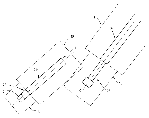
Figure 5 illustrates the envelopes, i.e.
exclusion zones, for the two machines shown in the figure
in a situation where there is a single envelope 13 for the
boom section 21 of each boom 5 and a single envelope 15
for the counterweight section 23 of each boom 5.
As is also stated above, the preferred system is
based on (i) detecting the intersection of the boundaries
of the exclusion zones of adjacent machines and (ii)
responding to detected intersections to avoid collisions.
The preferred system uses the following co-
ordinate system.
An origin (0,0) is defined.
~ The x-axis is parallel to the machine travel
tracks 3.
The forward (north) direction of travel is
defined as positive.
CA 02435018 2003-07-17
WO 02/058034 PCT/AU02/00048
- 10 -
~ The y-axis is perpendicular to the machine
travel tracks 3.
~ The west direction is defined as positive on
the y-axis.
~ All data transferred to the system has a base
unit of measurement of 0.1 metres and 0.1
degrees.
In order to detect the intersection of the
boundaries of the exclusion zones of adjacent machines,
the preferred system locates the envelopes in space and
then continuously determines whether the envelopes
intersect.
The means for locating the envelopes in space
includes sensors (not shown) on each machine for measuring
the slew angles of the booms 5 and the long travel of the
machines.
Each rectangular envelope is defined by its
corners, as follows:
(X1,Y1), (X2,Y2), (X3,Y3), (X4,Y4)
Collision detection is accomplished by
determining if any of the lines defining the envelopes of
one of the machines intersect the lines defining the
envelopes of an adjacent machine.
In order to determine whether a given envelope of
one machine intersects another given envelope of another
machine, the preferred system carries out the following
steps.
CA 02435018 2003-07-17
WO 02/058034 PCT/AU02/00048
- 11 -
1. Set (x0,y0) to one corner of one of the collision
envelopes to be examined.
2. Set (xl,y1), (x2,y2), (x3,y3), (x4,y4) to the corners
of the other collision envelope to be examined. These
points are defined in the sequential order obtained by
traversing the rectangular boundary in a clockwise
direction with point (xl,y1) being to the left (i.e.
anti-clockwise) of the boom tip or counterweight end.
3. If the angle from (xl,y1) to (x0,y0) is within the
range from (thetas+180 degrees) to (thetas+270 degrees)
and the angle from (x3,y3) to (x0,y0) is within the
range of from thetas to (thetas+90 degrees) then the
point (x0.y0) is enclosed within the boundary.
4. Steps 1. to 3. Are repeated for each point on both
envelopes.
In the preferred system with three envelopes for
the boom section 21 of the boom 5 (which define Zones 1,
2, and 3 as shown in Figure 4) and three envelopes for the
counterweight section 23 of the boom 5:
~ An intersection of the Zone 1 rectangles
provides a "Warning Function".
~ An intersection of the Zone 2 rectangles
results in the system disabling travel and
slew in the direction of intrusion on both
machines.
~ An intersection of the Zone 3 rectangles
results in the system disabling travel, slew
and tuff in all directions on both machines.
In order to respond to a detected intersection,
CA 02435018 2003-07-17
WO 02/058034 PCT/AU02/00048
- 12 -
the preferred system determines the minimum distance
between the adjacent machines and calculates angles
between selected points on the machines.
The preferred system then uses the calculated
angles to assess permissible slewing and travel movement
of the machines to move the machines away from an
intersecting situation and then moves the machines
accordingly.
It will be apparent that the envelopes axe sized
so as to allow the system to avoid collisions and that the
size of the envelopes may change dynamically in accordance
with any changing requirements to avoid collision - eg
changes to required braking distance.
Many modifications may be made to the present
invention as described above by way of example without
departing from the spirit and scope of the invention.
By way of example, the preferred system
described above does not take into account the Tuff angles
of the machines. However, it is noted that the present
invention extends to systems that consider the luff angles
of the machines.
By way of further example, the present invention
is not limited to the particular: (i) means for defining
envelopes around each boom that moves with the boom, (ii)
means for detecting an intersection of the boundaries of
the exclusion zones, and (iii) means responsive to a
detected boundary intersection to prevent collision of the
machines; described above.