Note: Descriptions are shown in the official language in which they were submitted.
CA 02435266 2003-07-17
WO 02/057808 PCT/US02/01377
APPARATUS AND METHOD FOR USING A SURFACE
OSCILLATOR AS A DOWNHOLE SEISMIC SOURCE
BACKGROUND OF THE INVENTION
1. Field of the Invention
The present invention relates to the field of acquiring seismic data and in
particular to a system for acquiring seismic data using a surface actuated
downhole source.
2. Description of the Related Art
Downhole seismic sources are used to determine the geological
to characteristics of the underground strata surrounding the borehole. The
objective
of such sources is to create seismic waves which propagate into the
surrounding
formation. Receivers, such as geophones, detect the seismic waves after they
have traveled through the geologic strata. Processing of these received waves
can
be used to determine the characteristics of the geologic formation including
those
of the various reflecting strata interfaces.
Various receiver techniques are used with downhole seismic sources.
These techniques include placing the receivers in adjacent offset wells, also
known as cross-well tomography. In another technique, the receivers are placed
on the surface of the ground to detect the downhole generated signal. This is
also
known as reverse vertical seismic profiling ("RVSP"). In another technique,
the
receivers are co-located in the same wellbore as the downhole seismic source.
CA 02435266 2003-07-17
WO 02/057808 PCT/US02/01377
Conventional downhole seismic sources are usually suspended down a
borehole from a cable which also provides power to operate the source and
conveys various sensor signals associated with the source back to the surface.
The
electrical driving power available to such devices is usually limited to a few
kilowatts by cable constraints. This power constraint limits the available
downhole signal strength and produces signals which have limited detectable
range within the formation. These sources are typically driven at their
maximum
power levels to maximize the transmission distance. In addition, these sources
do
to not use the received signals in a closed-loop system to adjust the
generated signal
to maximize the received signal. Thus there is a need for a seismic system
which
can generate sufficient power downhole to extend the detectable range of the
generated signals. This system should be capable of working in a stand-alone,
open-loop manner and in a closed-loop manner utilizing the received signals to
adjust the generated signal to maximize the detection range.
SUMMARY OF THE INVENTION
The present invention provides an improved system for generating
downhole seismic signals by overcoming previous limitations as to received
signal
strength and closed loop control of the vibratory source to maximize the
received
signal.
In one embodiment of the invention, a vibratory source is coupled by a
tubular string to a downhole anchor. The vibratory source is powered by a
power
source which can be a hydraulic, electric, or pneumatic system. Load and
motion
2
CA 02435266 2003-07-17
WO 02/057808 PCT/US02/01377
sensors are mounted on the tubular string both downhole and at the surface,
and
provide signals to a surface control unit for use in feedback control of the
vibratory source. Seismic sensors, such as geophones, may be deployed on the
surface, in offset wells, or in the same well as the source. These signals are
transmitted back to the control unit and may be used to control the vibratory
source so as to maximize the received signals.
In another embodiment, the surface vibratory source imparts axial motion
to a tubular string which is attached to a downhole hammer apparatus such that
l0 axial motion of the tubular string causes the downhole hammer to impart a
broadband signal which is transmitted into the surrounding reservoir
formation.
In one aspect of the invention a method of generating a downhole seismic
signal in a wellbore is presented which comprises (i) providing a vibratory
source
at a surface location; (ii) coupling the vibratory source to the upper end of
a
tubular string, anchoring the tubular string at a selected downhole location;
and
(iii) operating the vibratory source in an axial vibration mode to cause axial
vibratory displacement of the upper end of the tubular string thereby
transmitting
the vibrational motion to the anchor and inducing a seismic signal into the
2o surrounding formation.
An alternative method comprises (i) measuring parameters of interest and
transmitting the measurements to the surface control unit; and (ii)
controlling the
vibratory source based on the measurements of the parameters of interest.
3
CA 02435266 2003-07-17
WO 02/057808 PCT/US02/01377
Examples of the more important features of the invention have been
summarized rather broadly in order that the detailed description thereof that
follows may be better understood, and in order that the contributions to the
art
may be appreciated. There are, of course, additional features of the invention
that
will be described hereinafter and which will form the subject of the claims
appended hereto.
BRIEF DESCRIPTION OF THE DRAWINGS
For detailed understanding of the present invention, references should be
1o made to the following detailed description of the preferred embodiment,
taken in
conjunction with the accompanying drawings, in which like elements have been
given like numerals and wherein:
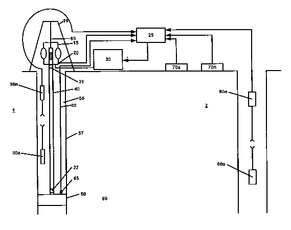
Figure 1 is a schematic illustration of a system for generating downhole
i5 seismic waves in a reservoir according to one embodiment of the present
invention; and
Figure 2 is a alternative arrangement of a downhole seismic source
according to the present invention.
DESCRIPTION OF THE PREFERRED EMBODIMENTS
Referring to Figure 1, the system is schematically illustrated. The
vibratory source 15 is attached to support cable 65 and supported by support
derrick 10. The vibratory source 15 is clamped to the upper, free end of
tubular
string 40. The tubular string 40 extends down the wellbore 55 to a location
where
4
CA 02435266 2003-07-17
WO 02/057808 PCT/US02/01377
it is desired to generate seismic waves in the reservoir formation 60. The
tubular
string 40 has an anchor 50 attached to the downhole end of the tubular string
40.
A number of commercially available devices can serve as the anchor 50,
including, but not limited to, a resettable packer, a resettable and
retrievable
bridge plug, a tubing hanger, or any other suitable device known in the art.
The
anchor 50 is activated at the desired downhole location so that the lower end
of
the tubular string 40 is essentially constrained from moving axially. Axial
oscillation of the upper, free end of tubular string 40 is vibrationally
transmitted
down tubular string 40 to the constrained Iower end and is transferred through
the
to anchor 50 as primarily shear waves into the reservoir formation 60. The
anchor 50
may be retrieved and reset at multiple downhole locations to provide seismic
input
to the forniation at multiple locations.
Alternatively, multiple fixed anchors (not shown), such as a tubing hanger,
may be permanently located at multiple locations in the wellbore 55 to provide
a
known location for taking seismic data at different times for comparison and
analysis of formation properties over time.
The surface located vibratory source 15 is powered by power source 30
which is controlled by a control unit 25. The control unit 25 contains a
processor
(not shown) which may be may be a microprocessor, a microcomputer, or a
computer with suitable capability to accept sensor inputs and provide output
control signals. The control unit 25 may also have mass data storage capacity.
Such devices are well known in the art and are not described further.
5
CA 02435266 2003-07-17
WO 02/057808 PCT/US02/01377
Vibration sensor 20 is mounted on the vibratory source 15 and generates
signals proportional to the vibrational motion of the vibratory source 15
which are
transmitted to control unit 25. Load sensor 21 is inserted in the tubulax
string 40
near the surface. Load sensor 21 generates signals proportional to the
vibration
force and the static force imposed on the tubular string 40 by the motion of
the
vibratory source I5 and by the weight of the tubular string 40.
Vibration sensor 45 is mounted proximate the downhole anchor 50 and
measures the characteristics of the downhole vibration imparted to anchor 50
and
to thus to the~reservoir 60.
Signals from the vibration sensor 45 are transmitted to the surface control
unit 25 via sensor cable 35 which may be an instrument cable, a standard
wireline
logging cable, an optical cable or a combination cable having both electrical
and
optical capabilities. Alternatively, the signals from vibration sensor 45 can
be
transmitted by acoustic or electromagnetic techniques known in the art.
Load sensor 22 is inserted in tubular string 40 proximate to anchor 50 and
measures the tension and compxession loads imparted to the anchor 50 due to
the
2o vibratory motion of and weight of the tubular string 40. Signals from the
load cell
are transmitted to the surface control unit 25 via sensor cable 35.
Alternatively,
the signals from load sensor 22 can be transmitted by acoustic or
electromagnetic
techniques to the control unit 25.
G
CA 02435266 2003-07-17
WO 02/057808 PCT/US02/01377
The control unit 25 is programmed to compare the signals from the surface
vibration sensor 20 and the downhole vibration sensor 45 and signals from the
upper load sensor 21 and the lower load sensor 22 to determine the
transmissibility of power from the vibratory source 15 to the anchor 50.
Seismic receivers 70a - 70n are mounted on the surface at a distance from
the source borehole 1. These receivers are typically geophones known in the
art
and sense the seismic signals imparted to the formation 60 by the system in
borehole 1. The receivers 70a - 70n may be deployed in predetermined patterns
on the surface to best determine the subsurface characteristics. The signals
from
receivers 70a - 70n are transmitted to the control unit 25.
Seismic receivers 80a - 80n are deployed in an offset borehole 2 and sense
the seismic signals at different depths in the offset borehole. The signals
from
receivers 80a - 80n are transmitted to control unit 2S. There may be multiple
sets
of receivers 80a - 80n deployed in multiple offset boreholes proximate the
source
borehole 1.
The signals from the receivers 70a - 70n and 80a - 80n may be processed
either separately or together by the control unit 25 and the results used to
modify
the operation of the vibratory source 15 so as to improve the signal at the
receivers
70a - 70n and 80a - 80n. Such modifications include but are not limited to
changing the frequency of the vibratory source 15 and changing the vibration
amplitude of source 15.
7
CA 02435266 2003-07-17
WO 02/057808 PCT/US02/01377
In a preferred embodiment referring to Figure 1, the surface vibratory
source 15 is a hydraulically driven device, such as Product No. 140-52 of
Baker
Oil Tools, a division of Balcer Hughes Incorporated. This device is also
described
in U.S. Patent No. 5,234,056, which is incorporated herein by reference. Such
a
device provides a highly elastic support so as to provide for a very low
impedance
to vibration at the upper end of tubular string 40. This vibratory source 15
is
designed to vibrationally isolate the tubular string 40 from the support
derrick 10.
'This vibratory source 15 can provide a typical surface axial displacement of
1 to 2
inches.
to
In this embodiment, the power source 30 is a servo-controlled hydraulic
system which can be controlled by the control unit 25 to vary the hydraulic
fluid
flow rate to the vibratory source 15 causing the vibratory source 15 to
vibrate at a
rate proportional to the flow rate thereby varying the frequency of axial
vibration.
The measurements of load from load sensors 21 and 22, and of vibratory motion
from vibration sensors 20 and 45 are transmitted to the control unit 25. The
load
and vibration data are used to determine the power transmissibility from the
surface to the downhole location. The load data is also used to limit the
amplitude
of vibration to safe levels. The control unit 25 also receives data from
receivers
70a - 70n and/or 80a - 80n. This receiver data is used to modify the source
signal
so as to maximize the signal at the receivers. The source signal may be
modified
in a closed-loop real time mode or alternatively, the data may be processed
and
the source signal modified sequentially. The receiver signals may also be
stored
in memory or on permanent storage media for later processing.
8
CA 02435266 2003-07-17
WO 02/057808 PCT/US02/01377
In a preferred embodiment the control unit 25 may be programmed to
generate a single frequency or alternatively it may be programmed to generate
a
swept frequency signal.
In another embodiment the signals from the same well receivers 90a - 90n
are transmitted to the control unit 25 and these signals are used to modify
the
source signal to maximize the signal received by 90a - 90n. The signals from
receivers 90a - 90n may also be stored in memory by the control unit 25. Those
received signals may also be stored, in either analog or digital form, on
permanent
1o storage media suitable for retrieval and subsequent processing.
In yet another embodiment, the receiver signals are transmitted to a
separate data storage system (not shown) for storage. The control unit 25
according to programmed instructions, uses signals from the load cells 21 and
22
and the vibration sensors 20 and 45 to control the source signal.
In still another embodiment, the source signal is controlled manually. The
load sensors 21 and 22 and the vibration sensors 20 and 45 use stand-alone
power
and display readouts (not shown). The operator manually controls the vibratory
source 15.
An alternative anchor embodiment is shown in Figure 2, where the tubular
string 40 is not axially axed in the downhole location, but instead uses the
cyclical
axial motion to impact an anchored anvil to generate broadband seismic waves
in
the formation. The operation of the equipment on the surface is essentially
the
9
CA 02435266 2003-07-17
WO 02/057808 PCT/US02/01377
same. A slip anvil 100 is anchored to the borehole. The slip anvil 100 may be
installed with techniques generally known in the art. The driver 110 is
attached to
the bottom of tubular string 40 and moves axially with tubular string 40. The
driver 110 can be of a two-piece construction (not shown) so as to allow
assembly
with the anvil 100. The driver 110 has tapered sections at each end of a
reduced
cross-section, such that each of the tapered sections alternatively impact
corresponding sections of the anvil 100 as the tubular string moves
alternatively
up and down in response to the motion of the surface vibratory source 15. The
driver 110 creates axial and radial impact forces which are coupled through
the
to slip anvil 100 into the reservoir formation 60 as seismic waves. These
seismic
waves project a broadband signal into the formation.
In one aspect of the invention a method for generating and receiving
seismic waves is presented which includes the steps for (i) attaching a
surface
mounted vibratory source to a tubular string in a borehole; (ii) controlling
the
vibratory source with a surface control system and a programmed processor;
(iii)
anchoring the tubular string to the wellbore at one or more locations
downhole;
(iv) operating the vibratory source to generate seismic waves which propagate
into
the surrounding formation; (v) measuring the load on the tubular string at the
2o surface and proximate the anchor; (vi) transmitting load and motion data to
the
processor; (vii) locating seismic receivers on the surface, in offset wells,
or in the
borehole with the source; (viii) transmitting the receiver data to the
processor; and
(ix) operating the processor, according to programmed instructions, to use the
load
data, the vibrational motion data, and the receiver data in a closed loop
control
mode to adjust the vibratory source in order to maximize the received signals
to
CA 02435266 2003-07-17
WO 02/057808 PCT/US02/01377
The foregoing description is directed to particular embodiments of the
present invention for the purpose of illustration and explanation. It will be
apparent, however, to one skilled in the art that many modifications and
changes
to the embodiments set forth above are possible without departing from the
scope
and the spirit of the invention. It is intended that the following claims be
interpreted to embrace all such modifications and changes.
11