Language selection

Search

Patent 2435565 Summary

Third-party information liability

Some of the information on this Web page has been provided by external sources. The Government of Canada is not responsible for the accuracy, reliability or currency of the information supplied by external sources. Users wishing to rely upon this information should consult directly with the source of the information. Content provided by external sources is not subject to official languages, privacy and accessibility requirements.

Claims and Abstract availability

Any discrepancies in the text and image of the Claims and Abstract are due to differing posting times. Text of the Claims and Abstract are posted:

  • At the time the application is open to public inspection;
  • At the time of issue of the patent (grant).
(12) Patent Application: (11) CA 2435565
(54) English Title: FIRE RESISTANT BARRIER
(54) French Title: ELEMENT COUPE-FEU
Status: Deemed Abandoned and Beyond the Period of Reinstatement - Pending Response to Notice of Disregarded Communication
Bibliographic Data
(51) International Patent Classification (IPC):
  • E04B 01/94 (2006.01)
  • E04B 09/00 (2006.01)
  • E04B 09/32 (2006.01)
  • E04F 19/00 (2006.01)
(72) Inventors :
  • MOSELLE, HAPPY (United States of America)
(73) Owners :
  • HAPPY MOSELLE
(71) Applicants :
  • HAPPY MOSELLE (United States of America)
(74) Agent: OYEN WIGGS GREEN & MUTALA LLP
(74) Associate agent:
(45) Issued:
(22) Filed Date: 2003-07-18
(41) Open to Public Inspection: 2004-01-19
Examination requested: 2008-05-08
Availability of licence: N/A
Dedicated to the Public: N/A
(25) Language of filing: English

Patent Cooperation Treaty (PCT): No

(30) Application Priority Data:
Application No. Country/Territory Date
10/199,565 (United States of America) 2002-07-19

Abstracts

English Abstract


A fire resistant assembly which may be used to ensure the fire resistance of a
fire
barrier such as a wall, comprising a first layer having a lumen therein, a
second layer
adjacent the first layer, and a box having a cavity defined by a wall, an
opening in the
wall, and a flange proximate the opening, wherein the box is disposed between
the first
layer and the second layer and wherein the opening is disposed on the lumen of
the first
layer.


Claims

Note: Claims are shown in the official language in which they were submitted.

What is claimed is:
1. A fire resistant assembly, comprising:
a first layer having a lumen therein;
a second layer adjacent the first layer; and
a box having a cavity defined by a wall, an opening in the wall, and a flange
proximate the opening,
wherein the box is disposed between the first layer and the second layer and
wherein the opening is disposed on the lumen of the first layer.
2. The apparatus of claim 1, wherein the fire resistant assembly further
comprises a first elongate structural member and a second elongate structural
member
and wherein the fire resistant wall is disposed between the two structural
members.
3. The apparatus of claim 2, wherein the box is attached to the first elongate
structural member.
4. The apparatus of claim 3, wherein the flange is attached to the first
elongate structural member.
5. The apparatus of claim 3, wherein the box is attached to the second
elongate structural member.
-7-

6. The apparatus of claim 1, wherein the angle between the flange and the
fire resistant wall is approximately 90 degrees.
7. The apparatus of claim 1, wherein the angle between the flange and the
fire resistant wall is greater than 90 degrees.
8. The apparatus of claim 1, wherein the fire resistant wall comprises
material having melting temperature greater than 1700° Fahrenheit.
9. The apparatus of claim 1, wherein the fire resistant wall comprises
stainless steel that is at least as thick as 30 gauge stainless steel.
10. The apparatus of claim 1, wherein the fire resistant wall comprises
stainless steel that is at least as thick as 24 gauge stainless steel.
11. The apparatus of claim 1, wherein the fire resistant wall comprises a base
wall and a perimeter wall.
12. The apparatus of claim 11, wherein the perimeter wall comprises welded
seams.
13. The apparatus of claim 1, wherein the lumen has a perimeter that is
smaller than a perimeter of the opening.
-8-

14. The apparatus of claim 1, further comprising a device disposed in the
lumen and extending into the cavity.
15. The apparatus of claim 14, further comprising a gap between the device
and the fire resistant wall.
16. The apparatus of claim 14, wherein the device is a electrical device.
17. The apparatus of claim 16, wherein the electrical device is a lighting
fixture.
18. The apparatus of claim 14, wherein the device is a drain.
19. The apparatus of claim 1, wherein the fire resistant assembly further
comprises a second layer, the box being disposed between the first layer and
the second
layer.
20. The apparatus of claim 19, further comprising a gap between the box and
the second layer.
21. The apparatus of claim 1, wherein the first layer is substantially
horizontal.
-9-

22. The apparatus of claim 1, wherein the first layer is a floor.
23 The apparatus of claim 1, wherein the first layer is a ceiling.
24. The apparatus of claim 1, further comprising lumens disposed in the
flange sized for receiving fasteners.
25. The apparatus of claim 1, further comprising means disposed on the flange
for attaching the box to a structural member.
26. The apparatus of claim 1, wherein the fire resistant wall further
comprises
a punch-out.
27. The apparatus of claim 1, wherein the fire resistant wall further
comprises
a removable area defined by one or more narrow grooves.
28. The apparatus of claim 1, having an ASTM E-119 fire endurance rating of
1 hour.
29. The apparatus of claim 28, further comprising a label certifying the box
to
have the ASTM E-119 fire endurance rating.
-10-

30. The apparatus of claim 29, wherein the label comprises paper.
31. The apparatus of claim 29, wherein the label is disposed on the box.
32. The apparatus of claim 29, wherein the label is printed on the box.
33. The apparatus of claim 29, wherein the label is applied to the box using a
method that displaces material of the box.
34. The apparatus of claim 33, wherein the method is selected from the group
consisting of stamping, engraving, and etching.
35. The apparatus of claim 1, wherein the fire resistant wall is impervious to
air flow.
36. A device for enclosing recessed devices and maintaining a minimum fire
endurance rating, comprising:
a cavity defined by a fire resistant wall;
an opening in the fire resistant wall;
a flange proximate the opening; and
an ASTM E-119 rating of 1 hour.
37. A method of providing a fire barrier in a building, the steps comprising:
-11-

providing a first layer;
providing a lumen in the first surface;
providing a second layer;
providing a box having a cavity defined by a wall, an opening in the fire
resistant
wall, and a flange proximate the opening disposed between the first surface
and the
second surface such that the opening in the box covers the lumen in the first
surface; and
disposing a device in the lumen and extending into the cavity of the box.
38. The method of claim 37, wherein the step of disposing the device further
comprises the step of providing a gap between the device and the fire
resistant wall.
39. The method of claim 37, wherein the step of providing a box further
comprises the step of providing a box having a punch-out, and further
comprising the
step of removing the punch-out to create an aperture in the box.
40. The method of claim 37, wherein the step of providing a box further
comprises the step of providing a box wherein an angle between the flange and
the fire
resistant wall is greater than 90 degrees.
41. The method of claim 40, wherein the flange is planar.
42. The method of claim 37, further comprising the step of providing a gap
between the box and the second flat building surface.
-12-

44. The method of claim 37, wherein the flat inner surface of the building is
a
ceiling.
45. The method of claim 37, wherein the flat inner surface of the building is
a
floor.
46. The method of claim 37, further comprising the step of attaching the
flange of the box to an elongate structural member of the building.
47. The method of claim 37, wherein the device is an electrical device.
48. A method of providing fire resistance in a building, the steps comprising:
providing a box having a cavity defined by a fire resistant wall, an opening
in the
fire resistant wall, and a flange proximate the opening; and
rating a box to provide the box with an ASTM E-119 fire endurance rating of
one
hour.
49. The method of claim 48, further comprising the step of providing a label
certifying the box to have the ASTM E-119 fire endurance rating.
-13-

Description

Note: Descriptions are shown in the official language in which they were submitted.


CA 02435565 2003-07-18
FIRE RESISTANT BARRIER
Field of the Invention
The invention relates to a fire barrier having a recess for a device. More
particularly, the invention relates to a recessed box installed in a building
for use with
maintaining a minimum fire endurance of a building surface.
Background of the Invention
Typically, a surface of a building such as a floor or a ceiling provides a
fire
barrier. A fire barrier resists the spread of a fire through it by providing a
resistance to
flammability, a resistance to heat transmission, and sufficient structural
integrity to resist
decomposing when exposed to heat or flames. The effectiveness of a fire
barrier~is often
rated by exposure to a fire of specified and increasing intensity and a rating
is a period of
time, typically in hours during which the fire barrier is effective. When an
aperture is
made in one of these fire barriers, the effectiveness of the fire barrier is
decreased
dramatically. Often it is nonetheless desirable to create an aperture in a
fire barrier, for
example, to install recessed lighting or a floor drain. To restore the fire
barner and
maintain an effective minimum resistance to fire, a construction worker will
typically
build a box of gypsum board and install it around the recessed fixture
proximate the
aperture created in the fire barrier. The construction of this box is a time
consuming task
and provides no mechanism to ascertain to what degree the effectiveness of the
fire
barner is restored.
-1-

CA 02435565 2003-07-18
Summary of the Invention
The present invention pertains to a prefabricated box suitable for use with a
wide
variety of recessed devices. The prefabricated box may be easily installed and
may
provide a known degree of fire endurance.
An embodiment of the invention pertains to a fire barrier. A box, comprising a
cavity defining a wall, a opening in the wall, and a flange proximate the
opening, may be
disposed between a first and a second layer, the opening of the box covering a
lumen of
the first layer. The box may be attached to a first and a second structural
member. A
device may be disposed in the lumen of the first layer and extend into the
cavity of the
box. There may be a gap between the device and the wall of the box and between
the
wall of the box and the second layer. The box may comprise steel or other
suitable
material and the wall of the box may be impervious to the passage of air. The
fire barrier
I S may be rated for 1 hour or greater fire endurance rating under ASTM E-I 19
or other
comparable test and certification of the rating may be found with or on the
box.
Brief Description of the Drawings
Figure 1 is a perspective view of box 100 for providing fire resistance
according
to the invention; and
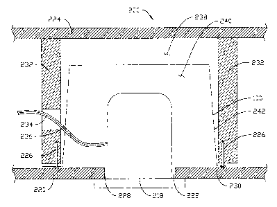
Figure 2 is a cross sectional view of box 100 positioned inside a fire
barrier.
-2-

CA 02435565 2003-07-18
Detailed Description of Illustrative Embodiments
Reference is now made to the figures, in which like element numbers refer to
like
elements throughout. Figure 1 is a perspective view of box 100, which includes
cavity
102 def ning a wall 104. Opening 106 provides access to cavity 102 and flange
108 is
disposed proximate opening 106. It is to be understood that, while wall 104 is
shown in
Figure 1 to be comprised of five flat surfaces and the opening, any shape
defined by a
cavity and having an opening may be suitable. For example, a cylinder open at
one end
may be suitable.
Flange 108 may be comprised of one or more individual pieces 110 and generally
defines a flat surface 112 facing away from cavity 102. Flange 108 is shown as
comprising a lip extending a uniform distance away from the edge of the
opening. It is to
be understood however, that many more configurations that may be suitable are
contemplated. For example, flange 108 may have struts which extend over the
opening
to provide means for attaching a device such as a light fixture. In addition,
flange 108
may have wings that extend from the opening to provide additional means for
attaching
the box in the fire barner. Flange 108 may include means for attaching box 100
to a
structural member such as lumens 114 for receiving nails or screws.
Wall 104 may include punch-outs 116 that permit ready removal with a hammer
or screwdriver for created additional openings to the cavity. Punch-outs 116
generally
comprises one or more grooves of reduced wall thickness formed in a closed
pattern.
Punch-outs 116 may be of several shapes and sizes to allow for the creation of
additional
openings adapted to specific tasks.
-3-

CA 02435565 2003-07-18
Figure 2 is a cross sectional view of box 100 disposed in a fire barner 200,
which
is fire resistant, and having a device 218 disposed therein.
The term "fire resistant" is herein defined to refer to the ability of a
structure to
serve as a barrier to the spread of fire. To serve as an effective barrier to
the spread of
fire, a structure must exhibit the following characteristics. First, it must
not pass flame or
hot gas from one side to the other. Second, the structure must support the
imposed design
loads without structural failure or collapse. Third, the structure must resist
the
transmission of heat so that the surface not exposed to the fire does not
exceed the
temperature of 250° F. Fourth, the structure must withstand lateral
impacts from falling
debris. This is definition of the term "fire resistant" as understood by those
of skill in the
art.
Fire barrier 200 is disposed in a building; suitable fire barriers may
comprise a
floor and a ceiling, a ceiling and a roof, or a wall and a wall. The fire
barner depicted in
Figure 2 comprises a ceiling and the floor above. Fire barrier 200 may be
comprised of a
first layer 220 having a lumen 222 therein, a second layer 224, and box 100
disposed
therebetween. Fire barrier 200 may also comprise structural members 224, such
as joists,
to which box 100 may be fastened using fasteners 226. Box 100 may also be
fastened
using other suitable means such as a high temperature epoxy or spot welding.
Lumen 222 generally has a perimeter 228 which may be smaller than the
perimeter 230 of opening 106. Layer 220, therefore, may extend over flange 108
and
perimeter 230. A device 232 may be disposed in lumen 222 and extend into
cavity 102.
This device may be any device installed in a fire barner. The device may be,
for
instance, an electrical device such as a light fixture or a fan, or it may be
a different
-4-

CA 02435565 2003-07-18
device, such as a floor drain. If device 232 is an electrical device, it may
have wires 234
extending therefrom. A punch-out of the appropriate size may be removed,
providing an
opening 236 though which wires 234 may extend. It may be desirable to provide
an
opening 236 that is not substantially larger than the cross section of the
objects extending
S therethrough in order to maintain the integrity of the fire barner. There
may be a gap 238
between wall 104 and layer 222 and there may also be a gap 240 between device
232 and
wall 104. These gaps may enhance the fire resistance of fire barner 200.
Layers 220 and 222 may comprise materials well known by those of skill in the
art such as gypsum board, plywood, plaster, or tile. Box 100 may be comprised
of steel
or other material having a melting temperature, for example, above
1700° Fahrenheit
such as ceramic. For example, box 100 may be comprised of 24-gauge stainless
steel.
This material may be galvanized to resist corrosion. Wall 100 may have a
perimeter wall
242 that has an angle with the flange of greater than 90 degrees. This may
facilitate
stacking of boxes 100. If box 100 comprises joints, these joints should be
sealed by
welding or another suitable process to make wall 104 substantially impermeable
to air
flow.
Fire barrier 200 should be capable of an ASTM E-119 fire resistance rating of
at
least 1 hour. A fire resistance rating of 1 hour exposes one side of the fire
barrier to the
following sequence of temperatures: 1000° F for 5 minutes, 1400°
F for 15 minutes,
1550° F for 30 minutes, and 1700° F for 10 minutes. At no time
during this test should
the fire barrier permit flames or hot gases through to the unexposed surface
or allow the
unexposed surface to exceed 250° F. This test was designed to simulate
the conditions a
real fire might expose a fire barrier to. Of course, if this test is updated
to reflect new
-5-

CA 02435565 2003-07-18
understandings of the conditions of a fire, the fire barrier should be capable
of a
comparable rating under the new test.
Fire barrier 200 may be rated under ASTM E-119 or a comparable test. The
process of rating includes creating a fire barrier 200 and subjecting it to
the test. A rated
fire barrier 200 may permit installation of box 100 in fire barners governed
by
regulations. Certification of the rating may be included with box I00.
Certification may
also be affixed on box 100, either on a label or permanently impressed into
box 100 by
stamping, etching or some similar process.
Numerous advantages of the invention covered by this document have been set
forth in the foregoing description. It will be understood, however, that this
disclosure is,
in many respects, only illustrative. Changes may be made in details,
particularly in
matters of shape, size, and arrangement of parts without exceeding the scope
of the
invention. The invention's scope is, of course, defined in the language in
which the
appended claims are expressed.
-6-

Representative Drawing
A single figure which represents the drawing illustrating the invention.
Administrative Status

2024-08-01:As part of the Next Generation Patents (NGP) transition, the Canadian Patents Database (CPD) now contains a more detailed Event History, which replicates the Event Log of our new back-office solution.

Please note that "Inactive:" events refers to events no longer in use in our new back-office solution.

For a clearer understanding of the status of the application/patent presented on this page, the site Disclaimer , as well as the definitions for Patent , Event History , Maintenance Fee  and Payment History  should be consulted.

Event History

Description Date
Inactive: Dead - No reply to s.30(2) Rules requisition 2013-04-17
Application Not Reinstated by Deadline 2013-04-17
Deemed Abandoned - Failure to Respond to Maintenance Fee Notice 2012-07-18
Inactive: Abandoned - No reply to s.30(2) Rules requisition 2012-04-17
Inactive: S.30(2) Rules - Examiner requisition 2011-10-17
Amendment Received - Voluntary Amendment 2011-06-20
Inactive: S.30(2) Rules - Examiner requisition 2010-12-20
Amendment Received - Voluntary Amendment 2010-07-06
Inactive: S.30(2) Rules - Examiner requisition 2010-01-07
Letter Sent 2008-07-21
Request for Examination Requirements Determined Compliant 2008-05-08
Request for Examination Received 2008-05-08
All Requirements for Examination Determined Compliant 2008-05-08
Inactive: IPC from MCD 2006-03-12
Inactive: Entity size changed 2005-06-20
Application Published (Open to Public Inspection) 2004-01-19
Inactive: Cover page published 2004-01-18
Inactive: First IPC assigned 2003-09-11
Inactive: IPC assigned 2003-09-11
Inactive: Filing certificate - No RFE (English) 2003-08-27
Application Received - Regular National 2003-08-27

Abandonment History

Abandonment Date Reason Reinstatement Date
2012-07-18

Maintenance Fee

The last payment was received on 2011-06-20

Note : If the full payment has not been received on or before the date indicated, a further fee may be required which may be one of the following

  • the reinstatement fee;
  • the late payment fee; or
  • additional fee to reverse deemed expiry.

Patent fees are adjusted on the 1st of January every year. The amounts above are the current amounts if received by December 31 of the current year.
Please refer to the CIPO Patent Fees web page to see all current fee amounts.

Fee History

Fee Type Anniversary Year Due Date Paid Date
Application fee - small 2003-07-18
MF (application, 2nd anniv.) - standard 02 2005-07-18 2005-06-08
MF (application, 3rd anniv.) - standard 03 2006-07-18 2006-04-21
MF (application, 4th anniv.) - standard 04 2007-07-18 2007-07-16
MF (application, 5th anniv.) - standard 05 2008-07-18 2008-04-08
Request for examination - standard 2008-05-08
MF (application, 6th anniv.) - standard 06 2009-07-20 2009-07-17
MF (application, 7th anniv.) - standard 07 2010-07-19 2010-07-06
MF (application, 8th anniv.) - standard 08 2011-07-18 2011-06-20
Owners on Record

Note: Records showing the ownership history in alphabetical order.

Current Owners on Record
HAPPY MOSELLE
Past Owners on Record
None
Past Owners that do not appear in the "Owners on Record" listing will appear in other documentation within the application.
Documents

To view selected files, please enter reCAPTCHA code :


To view images, click a link in the Document Description column. To download the documents, select one or more checkboxes in the first column and then click the "Download Selected in PDF format (Zip Archive)" or the "Download Selected as Single PDF" button.

List of published and non-published patent-specific documents on the CPD .

If you have any difficulty accessing content, you can call the Client Service Centre at 1-866-997-1936 or send them an e-mail at CIPO Client Service Centre.


Document
Description 
Date
(yyyy-mm-dd) 
Number of pages   Size of Image (KB) 
Description 2003-07-17 6 223
Claims 2003-07-17 7 162
Drawings 2003-07-17 2 52
Abstract 2003-07-17 1 13
Representative drawing 2003-09-11 1 21
Description 2010-07-05 6 216
Claims 2010-07-05 5 142
Filing Certificate (English) 2003-08-26 1 160
Reminder of maintenance fee due 2005-03-20 1 111
Reminder - Request for Examination 2008-03-18 1 119
Acknowledgement of Request for Examination 2008-07-20 1 177
Courtesy - Abandonment Letter (R30(2)) 2012-07-09 1 165
Courtesy - Abandonment Letter (Maintenance Fee) 2012-09-11 1 172
Fees 2007-07-15 1 34