Note: Descriptions are shown in the official language in which they were submitted.
~1
t
CA 02435567 2003-07-22
Method and Device for Sandblasting, Especially Removing in a Precise Manner
and/or
Compacting and/or Coating Solid Surfaces
The invention relates to a method for removing andlor compacting and/or
coating solid
surfaces such as removing defective spots of paint from coats of lacquer,
smoothing of
soldered and welded joints, removal of contaminated layers of concrete or rust
coatings or
hardening or planing metal surfaces wherein a (particle) blasting agent is
added by means of
gravity and/or due to the effect of an injector to a carrier air flow produced
by subatmospheric
pressure, conveyed in a flexible hose line system to a jet lance before being
guided onto a
processing surface exposed to subatmospheric pressure created by means of a
blasting
chamber, whereupon it is returned to the air flow, purified and, if
applicable, recirculated,
whereby acceleration of the blasting agent is produced by the subatmospheric
pressure and the
blasting chamber is displaced from one processing surface to another.
The invention also relates to a device for the application of the procedure
comprising at least
one container serving as a reservoir for a blasting agent, a dispensing and/or
injector device
connected with said container for dispensing appropriate quantities of the
agent into a
subatmospheric pressure air flow produced by means of a suction device, a
flexible hose
supply line connected with the dispensing and/or injector device to transport
the airflow
containing the blasting agent into a jet lance leading into a blasting chamber
wherein
subatmospheric pressure exists and comprising a nozzle for blasting of the
processing surface
and a flexible hose removal line connected with the blasting chamber and
serving to remove
by suction the blasting agent and the particles removed from the processed
surface out of the
blasting chamber into a separating container and a filter connected with the
suction device.
A method for dry removing of coatings, graffiti or other superficial
contaminations on plane
or curved surfaces is known from DE 197 47 838 A1. An abrasive or gentle
blasting agent is
added to a carrier air flow guided through a flexible hose line system,
transported by said air
flow, accelerated and guided onto the surface to be treated.
The blasting agent is then suctioned back into the carrier air flow by means
of the
subatmospheric pressure produced of 50 - 300 mbar, cleaned in a cleaning
device and
returned into the carrier air flow so that a recirculation process is
achieved. The mixture of
blasting agent and air is accelerated, in a straight acceleration movement, to
a jet speed of 20
t
CA 02435567 2003-07-22
' 2
- 80 m/s prior to hitting the processing surface, such acceleration being
achieved by reducing
the diameter from the supply section to the accelerating section.
The jet speed that can be achieved by means of said diameter reduction is
sufficient to achieve
an abrasive effect adequate to treat graffiti or other superficial
contaminations. It is, however,
not sufficient to smooth hard surfaces such as soldered or welded joints, and
therefore the
known method is uneconomical. This applies also to the removal of rust from
metallic
surfaces or the removal of contaminated layers of concrete.
On the other hand, the energy furnished in the device disclosed under DE 197
47 838 A1 is
much too high for the removal of punctiform inclusions in coats of lacquer.
Mufti-layered
coats of lacquer can be up to 150 p.m thick, as is well known, and consist
from the outside to
the inside of a clear lacquer coat and a base lacquer coat, a filler coat and
a primer coat.
Blemishes in the lacquer coat occur, in particular, in metallic lacquer coats
of car body
components and are mainly caused by punctiform or more extended inclusions in
the clear
lacquer or base lacquer coat. These blemishes require reworking involving
great cost and
effort because the diameter reduction described above allows regulation of the
jet speed only
to a limited extent, which results in destruction or impairment of the entire
lacquer coat where
the particles of the blasting agent hit the processing surface with excessive
speed or an
uneconomic effect where they hit the processing surface with insufficient
speed.
Under DE 196 14 555 A1 a device for abrasive blasting of work pieces is
disclosed which
comprises a chamber essentially closed air-tight on all sides with at least
one but preferably
several closable openings from which chamber the air can be evacuated, a
container holding
the blasting agent and a blasting tube unit that can be inserted into the
chamber through one of
the closable openings and is provided with an inlet opening for the blasting
agent, an inlet
opening for air and an outlet opening for the blasting agent wherein the inlet
for the blasting
agent can be connected, by means of a supply line, to the container holding
the blasting agent.
In this solution, a jet lance is used to convey the blasting agent, said jet
lance comprising an
opening for air serving to suction in the blasting agent. The jet lance has a
consistent diameter
and is not provided with an additional injector within the body of the jet
lance. This known
solution is therefore not suited to produce appropriately high jet speeds for
removal and/or
CA 02435567 2003-07-22
~ ~ 3
compacting and/or coating processes. All disadvantages indicated above
therefore also
characterize this state of the art.
Considering this state of the art, the invention serves the purpose of
improving a method and
device of the type indicated above in such a way that the jet speed is
increased in a significant
manner while at the same time economically adjusting the amount of energy
furnished via the
blasting agent to the processing surface for various wide-ranging applications
and within wide
limits, using a small amount of energy, providing high flexibility and
economically
compatible recovery and reutilization of the blasting agent.
This task is solved through a method of the type indicated above with the
characterizing
features described in claim 1 and through a device with the characterizing
features indicated
in claim 12. Advantageous embodiments of the method and the device are
described in the
sub-claims.
The method disclosed hereunder is mainly characterized by the fact that the
speed of the
blasting agent can be regulated within wide limits, e.g. between >80 and 1000
m/s, depending
on the type and shape of the processing surface and of the blasting agent, the
concentration of
the blasting agent within the carrier air flow, the subatmospheric pressure of
the carrier air
flow, the blasting time and the jet temperature. Therefore, the method
disclosed hereunder can
equally be used for removing blemishes from lacquer coats, for smoothing and
planing
soldered joints or, for example, for removing contaminated layers of concrete
or for
compacting or coating surfaces.
The device for implementing the method disclosed hereunder is simple but
robust. It works
with a carrier air flow of between 0.1 m3 / h and 5000 m3/h.
Further advantages and details are indicated in the description rendered below
with reference
to the enclosed drawings.
The invention is explained in detail below on the basis of several examples of
favorable
designs.
Fig. 1 provides an illustration showing the functioning of the method
disclosed hereunder.
l
CA 02435567 2003-07-22
4
Fig. 2 shows a section through the injector within the flexible hose supply
line.
Fig. 3 provides an illustration showing the operating principle of an
embodiment of the
device disclosed hereunder for removing punctiform blemishes in coats of
lacquer.
Fig. 4 provides a view of the blasting chamber, the jet lance, the jet
aperture and the
magnetic foil pursuant to Fig. 3.
Fig. 5 provides an illustration showing the operating principle of an
embodiment of the
device disclosed hereunder for smoothing soldered joints.
Fig. 6 provides a view of the blasting chamber, the jet lance and the mask
pursuant to Fig. 5.
Fig. 7 shows a section through a soldered joint connecting two metal sheet
components with
a blasting chamber positioned on the joint.
Fig. 1 shows the functioning principle of the method disclosed hereunder for
blasting a
vertical plane processing surface ( 1 ) with a blasting agent (2). The
blasting agent (2) consists
of broken glass, corundum, zircon sand, fine-grained slag or steel particles.
A suction device (3) is used to produce a carrier air flow (4) with a flow
rate between 0.1 m3/h
and 5000 m3/h. The suction pipe (5) of the suction device (3) is connected
with a flexible hose
removal line (6) that leads to a blasting chamber (7). The suction device (3)
is used to produce
a subatmospheric pressure between >150 and 1000 mbar. The container (8)
contains two
hoppers (9) and (10) arranged vertically above and pneumatically separated
from each other.
Gravity causes the blasting agent (2) to flow from hopper (9) into hopper (
10) and from there
into the dispensing device (11) with a horizontally arranged dispensing
injector (12) that is
connected with the flexible hose supply line (13). The subatmospheric pressure
applied
suctions the blasting agent (2) forward which together with the carrier air
flow flows, within
the flexible hose supply line (13) towards a jet lance (14) (14) that leads
into the blasting
chamber (7). From the blasting chamber (7), the mixture of blasting agent, air
and removed
particles is led through the flexible hose removal line (6) to a separator or
cyclone (22) where
CA 02435567 2003-07-22
the blasting agent is removed from the carrier air flow before the removed
particles are
removed from the carrier air flow by means of a filter and the carrier air
flow is returned to
the suction device (3).
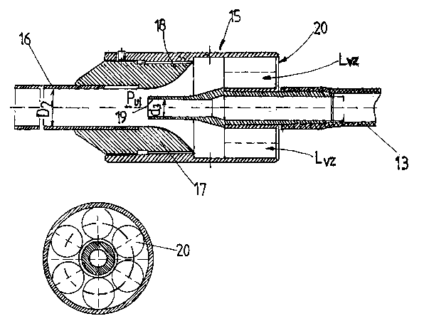
Fig. 2 shows a section through the injector (IS) inserted into the flexible
hose supply line
(13), the mixing pipe (16) of the injector leading into the blasting chamber
(7). The injector
( 15) consists of a nozzle body ( 17) with an inlet opening ( I 8) of a
narrowing cone-shape
design that leads into the mixing pipe (16). The end (19) of the flexible hose
supply line (13)
is centrally arranged on the axis A-A of the nozzle body and ends in the area
where the
narrowing of the cross section of the nozzle body ( 17) reaches its maximum.
Arranged in a
coaxial pattern relative to the flexible hose supply line (13), a number of
suction openings are
arranged as a suction ring (20) serving to suction in atmospheric air. The
diameter D2 of the
mixing pipe (16) is approximately twice as large as the diameter d3 of the end
(19) of the
flexible hose supply line ( 13) so that the air flow LvZ entering via the
suction ring (20)
produces a subatmospheric pressure PU, that results in an additional intake of
the mixture of
carrier air and blasting agent through the suction openings (20) and
acceleration of the same.
The air flow IvZ acts on the mixture of carrier air and blasting agent like an
energy pulse and
increases its speed. Thus jet speeds of up to 1000 m/s are achieved.
Depending on the type of material, the type of processing surface and the type
and form of the
blasting agent, the jet speeds can be adjusted to the respective processing
task by regulating
the air volume Lvz , varying the subatmospheric pressure applied, the blasting
time, the jet
temperature and the geometric circumstances at the injector (15). All
essential components of
the device disclosed hereunder can be arranged in a modular pattern depending
on the
respective application.
Example 1
Blemishes in the coat of lacquer on a car body component are removed using the
method
disclosed hereunder.
Fig. 3 shows a variant of the device disclosed hereunder that is to be used to
implement the
process disclosed hereunder.
CA 02435567 2003-07-22
6
The device pursuant to Fig. 3 essentially consists of a blasting chamber (7)
with a jet lance
(14) arranged therein, a screw-type dispensing device (11) connected with the
jet lance (14)
by means of the flexible hose supply line (13), a storage container (44)
holding the blasting
agent (2) connected by means of a feed line (45) with the screw-type
dispensing device, an
extraction pipe (21) leading on one side into the blasting chamber (7) and on
the other side via
the flexible hose removal line (6) into a separator (22), and a suction device
(3) connected
with the same on the suction side.
The blasting chamber (7) consists of a cylindrical sleeve body (23) containing
an internal
reception space (24) as shown in Fig 4. The thin jet lance (14) is inserted
into the internal
reception space (24) along the axis of the sleeve B-B through a bore (25) in
the upper wall
(26) of the sleeve and clamped into the bore by means of a screw.
The end of the sleeve body (23) opposite the upper wall (26) of the sleeve is
open and
provided with an opening (28) in the wall (27) of the sleeve into which an
aperture body (29)
is inserted. The aperture body (29) closes the reception space (24) of the
sleeve body (23).
The aperture body (29) is provided with a circular opening (30) which flares
like a funnel
(cone shape) towards the inside. The aperture body (29) consists of a non-
wearing material,
the outside of which is covered with a magnetic foil (31 ). In an advantageous
embodiment,
the magnetic foil (31) is bonded onto the aperture body (29) and provided with
a
corresponding opening (32) the position of which coincides with the opening
(30) of the
aperture body (29).
The jet lance (14) is inserted into the reception space (24) in such a way
that the outlet
opening (33) of the jet lance (14) is located near the opening (30) of the
aperture body (29).
The opening leading into the extraction pipe (21 ) is located a small distance
below the upper
wall (26) of the sleeve at a sufficient distance from the outlet opening (33)
of the jet lance
(14) into the sleeve body (23).
The drive of the screw-type dispensing device (11) can be switched off by
means of a time
relay (34). The screw-type dispensing device (11) therefore only transports
blasting agent out
of the container (44) until the time relay (34) switches off the drive.
i
CA 02435567 2003-07-22
7
The process disclosed hereunder is implemented as follows. One or several
specimens of
metal sheet bearing a coat of lacquer are, after determining the thickness of
the coat of
lacquer, used to determine the blasting time and amount of blasting agent
required to remove,
for example, the clear lacquer coat and the base lacquer coat down to the
filler coat, thus
determining the energy required to be furnished to the blemish. The switching
time of the
time relay (34) of the screw-type dispensing device (11) is set to the time
value thus
determined and the previously determined amount of blasting agent is added to
the carrier air
flow.
In the case of a metallic lacquer consisting of a primer coat of approximately
18 pm, a filler
coat of approximately 25 pm, a base lacquer coat of approximately 12 pm and a
clear lacquer
coat of approximately 35 pm, a switching time of 14 seconds and a quantity of
7 g of a
blasting agent with a grain size of 80 p.m have proven advantageous.
After the end of the switching time, the time relay (34) switches off the
screw-type dispensing
device (11). No more blasting agent is fed into the carrier air flow produced
by the suction
device though the carrier air flow is maintained while the screw-type
dispensing device (1 I) is
deactivated and transports the used blasting agent through the extraction line
(46) into the
separator (22). In the separator (22) a cyclone (47) separates the blasting
agent (2) from the
removed lacquer particles which are transported into a filter (35) by the
suction device (3).
Then the result of the blasting process is subjected to a visual inspection,
thus determining
whether or not the inclusion has been removed from the coat of lacquer. If
this is not the case,
the screw-type dispensing device (11) is reactivated. The screw-type
dispensing device
subsequently feeds blasting agent into the carrier air flow until the time
relay (34) switches of
the screw-type dispensing device ( 11 ).
The energy required to be furnished to the blemish to remove the included
particle from the
coat of lacquer can be adjusted and regulated with great precision by
modifying the type of
blasting agent, the blasting time and the quantity of blasting agent.
Example 2
CA 02435567 2003-07-22
. 8
The method disclosed hereunder is used for smoothing and planing a soldered
joint (36)
connecting to curved metal sheet components (48). Soldered joints are always
characterized
by a certain degree of unevenness resulting from the hardening of the molten
metal. In the
course of a subsequent lacquering process, this unevenness impairs the
evenness of the
lacquer coat applied in the area of the soldered joint.
Fig. 5 shows an embodiment of the device disclosed hereunder that can be used
for smoothing
such soldered joints, the design of the device corresponding to the system
described above.
In Fig. 6, the blasting chamber (7) is shown, consisting of a body (37) to be
positioned on the
part to be processed of the surface of the soldered joint (36), a jet lance
(14) inserted into the
body (37) so as to reach a position close to the soldered joint (36) at an
angle a relative to the
plane N perpendicular to the soldered joint (36), a cover mask (38) closing
the body (37), a
slot-shaped outlet opening (39) for the blasting agent corresponding to the
shape of the
soldered joint and an extraction pipe (40) characterized by a funnel-like
flaring shape. The jet
lance (14) is provided with a slot shaped end (41) the longitudinal dimension
of which
approximately corresponds to the longitudinal dimension of the processing
surface of the
soldered joint (36). Thus it is ensured that blasting agent can be evenly
applied to the entire
processing surface of the soldered joint (36). The jet lance (14), as
described above, is
connected with the flexible hose supply line (13) in which the additional
injector (15)
described in detail above is arranged.
The cover mask (38) is connected with and supported by a foam rubber pad (42)
which in the
present example is divided into two sections so as to be able to compensate
for height
differences in the area of welded joints (36) between the edges of metal sheet
components
(see Fig. 7). For this purpose, the two sections (42a and 42b) of the foam
rubber pad (42) are
of different thickness. The foam rubber pad (42) may, for example, be caused
to adhere to the
metal sheet components by means of a magnetic foil so that easy displacement
along the
soldered joint to be processed is possible. Fixation may, of course, also be
effected by
mechanically applied forces, e.g. through a vacuum or through adhesion.
The foamed rubber pad (42) as a wearing component ensures largely air-tight
sealing of the
blasting chamber (7) as it covers irregularities.
CA 02435567 2003-07-22
9
In the present example, the method disclosed hereunder is applied with a
subatmospheric
pressure of 320 mbar, a carrier air flow of 180 m3/h and a jet speed of the
agent of
approximately 180 m/s.
Example 3
The invention disclosed hereunder is used to remove a contaminated layer of
concrete from a
concrete surface. The design of the device disclosed hereunder corresponds to
the principle
design described above. The carrier air flow of 3000 - 5000 m3/h produced by
the suction
device (3) is divided and guided to a number of separate jet lances (14)
arranged in a fan-like
pattern through separate flexible hose supply lines (13). Each of the flexible
hose supply lines
(13) is provided with an injector (15) that provides an additional energy
pulse to the mixture
of carrier air flow and blasting agent so as to significantly increase the jet
speed. All jet lances
(14) lead into a common blasting chamber (7) which can be displaced on the
concrete surface.
The suction device (3) creates a subatmospheric pressure of 400 - 500 mbar,
and jet speeds of
approximately 300 m/s are reached.
The mixture of blasting agent and concrete particles is transported via the
flexible hose
removal line (6)into the separator (22) where the blasting agent is removed,
filtered and
recirculated into the closed circuit.
In a fine filter, the blasting agent is separated from the removed concrete
particles. The
cleaned carrier air flow then is recirculated into the suction device (3).
The process disclosed hereunder can without difficulty remove a layer of 10 mm
from a
surface of 4.6 m2 per hour.
The method disclosed hereunder allows adjustment of the thickness of the layer
removed, thus
ensuring that no more than the amount of concrete actually required to be
removed is
eliminated in the case of contaminated concrete.
Thus the amount of concrete that must be disposed of or treated as special
waste is kept as
small as possible.
Example 4
CA 02435567 2003-07-22
The method disclosed hereunder is used to compact the upper section of a
surface. For this
purpose, the method disclosed hereunder is applied as described above. A
blasting agent
consisting of steel is used which compacts the processed surface as it hits
it, thus achieving a
surface hardening effect.
The blasting agent consists, depending on the type of material to be
compacted, for example
from spherical steel particles with a diameter between SOpm and 5000 prn. The
jet speed
exceeds 250 m/s.
Example 5
The invention disclosed hereunder is used to apply a zinc-coating on a surface
compacted as
described in example 4 above. The blasting agent in this case consists of zinc-
particles with a
grain size of 20 pm . These particles are accelerated to a speed of 180m/s by
means of an
injector (15). As the zinc particles hit the surface, their kinetic energy is
converted into an
amount of thermal energy that is sufficient to create a layer of zinc on the
surface.
List of components referred to and numbers allocated thereto:
Processing surface
Blasting agent 2
Suction device
Carrier air flow 4
Suction pipe
Flexible hose removal line
Blasting chamber
Container g
Hopper within 8 9, 10
Dispensing device, screw-type dispensing 11
device
Dispensing injector 12
Flexible hose supply line 13
Jetlance 14
Injector 15
CA 02435567 2003-07-22
11
Mixing pipe 16
Nozzle body of 15 1 ~
Inlet opening 1 g
End of the flexible hose supply line 19
13
Suction ring with suction openings 20
Extraction pipe 21
Separator, cyclone 22
Cylindrical sleeve body 23
Internal reception space of 23 24
Upper wall of the sleeve 25
Bore 26
Wall of the sleeve 2~
Opening 2g
Aperture body 29
Opening 30
Magnetic foil 31
Opening in 31 32
Outlet opening of 14 33
Time relay 34
Filter 35
Soldered joint 36
Body of 7 3~
Cover mask 3g
Outlet opening in 38 39
Extraction pipe 40
End of 14 41
Wearing pad, foamed rubber pad 42
Sections of 42 42a, 42b
Divided magnetic foil 43
Storage container for blasting agent 44
Feed line 45
Extraction line 46
Cyclone in the separator 4~
Axis of the nozzle body A-A
CA 02435567 2003-07-22
12
Axis of the sleeve body B-B
Diameter of the mixing pipe d2
Diameter of the end of the flexible hose supply line d3
Plane perpendicular to the processing surface N
Additional subatmospheric pressure in injector 15 Pur
Angle of the jet lance a