Note: Descriptions are shown in the official language in which they were submitted.
CA 02435851 2003-07-23
0179P308CA01
A CYCLONE SEPARATOR SgJITABI.E FOR VARIABLE FLIlED FLOW
RATES.
BACKGROUND of the INVENTION.
Specifically, though not exclusively, the invention is usefully applied in
separating solid particles discharge fluids in dental apparatus.
As is well known, dental aspiration plants remove fluids from the mouth of a
patient during an operation. These fluids comprise a gaseous part (generally
air), a liquid part (generally water, blood and other liquids which are used
in
dental apparatus) and a solid part in particle form (usually the amalgam used
in
fillings). The aspirated fluids contain various polluting substances, such as
for
exainple solid particles of ainalgam. In dental. apparatus the production of
polluting fluids can be quite abundant, although generaily discontinuous.
These
fluids, before being discharged into the sewers, must be freed of polluting
substances.
The prior art teaches separating the solid particles from the fluids by means
of
a cyclone separator which exploits the centrifugal force developed by creating
a rapid vortex in the fluid flow in which the solid particles are suspended.
These cyclone separators comprise a recipient having an inlet for the fluid
and
an upper outlet for the fluid fi=oin which the solid particles have been
removed.
The separator recipient has a downwards-converging truncoconical shape, at
the narrow end of which there is a discharge that can be connected to a
container in which the solid particles can be collected.
These separators, of extreinely simple construction, operate without any
extemal motor and entirely by the creation of a centrifugal force impressed on
the particles to be separated by the fluid movement. The particles to be
CA 02435851 2006-09-22
-2-
separated are projected against the walls of the recipient and descend towards
the bottom of the separator while the fluid rises in the secondary vortex
created
in the central part of the separator and exits from the top part of the
separator.
The degree of separation of the particles greatly depends on the fluid flow
rate
crossing the centrifuge. With low flow rates, these separators are not able to
guarantee a sufficient level of separation of the solid particles which,
especially
for use in dental apparatus, inust be at least 95% of the total of the
particles
contained in the fluid.
To obviate the above-described drawback, the prior art teaches a cyclone
separator, described in EP 0 557 251, by the same applicant. In this
separator,
the efficiency and peiformance of the separation are increased thanks to the
use
of a centrifugal pump the blade of which, located internally of the recipient
and
above the truncoconical part, can rotate so as to accelerate the speed of the
water independently of the flow rate, and thus performs a first separation of
the
particles by centrifugation. The use of a centrifuge pump, which enables the
separator to function both as a centrifuge separator and as a cyclone
separator,
is however somewhat coinplicated in construction and therefore expensive.
Furthennore, to pass froin centrifuge to cyclone operation, the above-
described separator requires the use of a solenoid valve commanded by an
electrical signal coining froin outside the separator, closing or opening the
outlet of the separator by a command which is independent of the operative
conditions of the separator. This creates yet another consti-uctional
complication and also means that the separator is dependent on the functioning
of an external device.
In European patent EP 0 933 066 , by the satne applicant, the prior art also
teaches another solution, which has a special confoi7nation and arrangeinent
of
the fluid inlet and outlet holes in the separator. This separator,
constructionally
CA 02435851 2003-07-23
-3-
very simple, increases the efficiency of the separation, but cannot operate
with
very slow flow rates.
The main aim of the present invention is to obviate the above-mentioned
drawbacks in the prior art by providing a cyclone separator wh.ich is
constructionally very simple and economical and which at the same time can
provide a high degree of separation, independently of the flow rate of the
fluid
reaching the separator.
An advantage of the device is that there is no need for an auxiliary motor or
coanmand signals from the outside of the device to operate it.
A further advantage of the device is that it can be cleaned and maintained by
very simple and easy operations.
These aims and more besides are achieved by the object ofthe invention as it
is
characterised by the accompanying clavns.
SUMMARY of the INVENTION.
The cyclone separator with flow rate regulation is for separating solid
particles
from a fluid, especially in dental apparatus. The separator cornprises a
recipient
having an inlet for the fluid and an upper outlet for the fluid once the solid
particles have been removed therefrom. The separator also comprises a
recycling conduit which places an outlet conduit in cominunication with the
inlet, a three-way valve to an inlet of which the outlet conduit is connected,
and
to outlets of which the recycling conduit and the outlet are connected. The
three-way valve has ara obturator which can block the connection between the
outlet conduit and the recycling conduit, a one-way valve which has an
obturator and is located at the outlet downstream of the three-way valve. The
one-way valve is nonrmlly closed and can connect the outlet conduit with the
outlet. The three-way valve and the one-way valve are brought into action
when the fluid pressure in outlet fiom the separator reaches first and second
CA 02435851 2006-09-22
-4-
predetermined values.
In a first broad aspect, the present invention seeks to provide, a cyclone
separator suitable for variable fluid flow rates, for separating solid
particles
dispersed in a fluid, comprising a closed recipient superiorly closed by a lid
provided with a recipient inlet for the fluid including the solid particles
and
a recipient outlet for the fluid purified of the solid particles, the
recipient
having a truncoconical wall converging in a downwards direction, a narrow
end of the truncoconical wall having a discharge constructed and arranged
to be connected to a container for collecting the solid particles, and an
outlet conduit for outletting the fluid from the recipient, wherein the
cyclone separator further comprises: a recycling conduit for placing the
outlet conduit in communication with the recipient inlet of the fluid; a
three-way valve having a body and a three-way valve inlet operatively
connected to, and constructed and arranged to receive fluid from, the outlet
conduit and having a first outlet connected to the recycling conduit, and
having a second outlet, the three-way valve being further provided with a
first obturator commanded by a pressure exerted by the fluid exiting from
the outlet conduit, the first obturator constructed and arranged to block a
connection between the outlet conduit and the recycling conduit when the
pressure reaches a first predetermined value; a one-way valve having a
body and a one-way valve inlet operatively connected to the three-way
valve, the one-way valve being provide with a second obturator
commanded by a pressure exerted by the fluid outletting from the outlet
conduit, such that when the pressure exerted by the fluid reaches a second
CA 02435851 2006-09-22
-4A-
predetermined value above the first predetermined value the one-way valve
moves from a normally closed first position to an open second position to
provide a connection between the outlet conduit and the fluid discharge
outlet.
BRIEF DESCRIPTION of the DRAWINGS.
Further characteristics and advantages of the invention will better emerge
from
the detailed description that follows, of a preferred but non-limiting
einbodiment illustrated purely by way of example in the accoinpanying figures
of the drawings, in which:
figure 1 is a scheinatic section in vertical elevation of the separator of the
invention;
figure 2 is a section in vei-tical elevation in enlarged scale of' the lid of
the
separator;
figure 3 is a view fi-om above, with soine parts removed better to evidence
others, of the lid of the separator.
DESCRIPTION of the PREFERRED EMBODIMENTS.
With reference to the figures of the drawings, 1 denotes in its entirety a
cyclone
separator of solid particles dispersed in a fluid which is used especially for
the
separation of the solid particles suspended in discharge fluids coining from
dental apparatus, of known type and not illustrated. In these plants there is
a
production of fluids containing air, water, blood, amalgam, chernical
products,
etc., which must be discharged to the sewers according to anti-pollution laws
which rule that ceitain substances, including ainalgatn and the like, cannot
be
discharged to the sewers. In the above-mentioned apparatus the production of
polluting fluids is rather abundant though discontinuous. The separator of the
CA 02435851 2006-09-22
-4B-
invention has the ai.un of freeing the fluids of these polluting particles,
independently of the flow rate of the fluid reaching the separator.
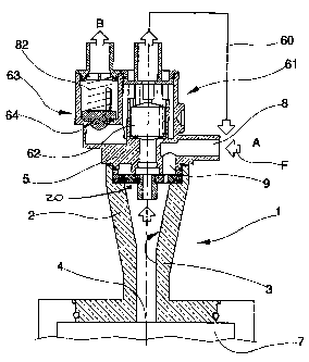
The separator 1 coinprises a recipient 2 which is connected to an inlet A for
receiving the fluid in which the solid paiticles to be separated are
suspended,
and also comprises an upper outlet B for discharging the fluid minus the solid
CA 02435851 2003-07-23
-5-
particles. The recipient 2, which can be made for example of a plastic
material,
is provided with a truncoconical wall 3 converging in a downwards direction,
at the narrow neck of which a discharge 4 is located. The discharge 4
communicates with a lower collection container 7 in which the separated solid
particles are accumulated.
The recipient 2 is superiorly closed by a lid 5, made for example of a plastic
material, which can be coupled removably to the recipient 2, for exaaanple
using
fixing screws. In the preferred embod'unent, the lid 5 is associated to both
inlet
A and outlet B.
The lid 5 laterally exhibits a fu=st mouth 8 which affords the inlet A for
receiving the fluid coming from the dental apparatus in the direction
indicated
by an arrow F. In this embodiment the first mouth. 8 is constituted by a
horizontal-axis cylindrical tube solidly connected to the lid 5.
An end of the tube, comprising the inlet A and projecting laterally from the
lid
5, is connectable to means for delivering the fluid containing the solid
particles
to be separated. The opposite end ofthe tube is u.nited to the material of the
lid
and corrnnunicates, through a vertical-axis conduit 9 afforded in the lid 5,
with an underlying annular chainber 10 afforded in the lid 5 and not in
contact
with the outside. The chainber 10 is separated froin the internal cavity of
the
recipient 2 by means of a lower wall 11 of the lid 5 which superiorly delimits
the cavity.
The cha.inber 10 afforded in the lid 5, and therefore inlet A of the fluid,
communicates with the inside of the recipient 2 through holes 12, made in the
lower wall 11 of the lid 5, which preferably exhibit an oblique axis directed
tangentially with respect to the vertical axis of the truncoconical wall 3.
The structure of the above-described lower wall 11 is such as to fi=action the
total flow of the fluid arriving via the inain inlet A into a plurality of
small jets
CA 02435851 2006-09-22
-6-
which are injected tangentially in the truncoconical zone of the recipient 2.
The lid 5 externally comprises a flanged lateral part 52 bearing means, of
known type and not illustrated, for removably coupling with a corresponding
flanged part ofthe underlying recipient 2, and a lower cylindrical part 53
which
is for insertion (and detachment) in a corresponding cavity 20 located
immediately above the truncoconical wall 3. Seals, comprising in the
illustrated
example an annular seal 6, are interpositioned between the cylindrical part 53
of the lid 5 and the cylindrical part of the recipient 2.
The lid 5 further exhibits a vertical-axis tubular body 54 which projects
inferiorly and the internal cavity of which, which is coaxial to the
truncoconical
wall 3 of the recipient 2, defines an outlet conduit 55 for the fluid from the
recipient 2 which outlet conduit 55 is crossed in an upwards dii-ection by the
fluid, fi-eed of the heaviest paiticles, as it exits the recipient 2.
The above is common to the prior a.rt described in above-cited European patent
EP 0 933 066 ; it is stressed, however, that the characteristics ofthe
separator
of the invention, as it will be illustrated herein below, can be applied also
to a
separator exhibiting a fluid inlet systein (for exainple without the lower
wall 11
or having inlet holes atTanged differently) as well as a coupling systein
between
the upper part and the recipient that are different fi-om the ones described.
The separator of the invention comprises a recycling conduit 60 which, as will
be inore fully explained herein below, places the outlet conduit 55 in
corrununication with the fluid inlet A. In the accompanying figures of the
drawings the recycling conduit 60 is illustrated schematically. The recycling
conduit 60 is connected upsti-eain of the pump, not illustrated, which
introduces
the fluid into the separator; tlus is to prevent the pmnp from pumping fluid
through the recycling conduit 60.
The lid 5 inteinally affords a tluee-way valve 61, an inlet 61 a of which is
CA 02435851 2003-07-23
-7-
connected to the outlet conduit 55, and outlets 61b and 61c of which are
connected to the recycling conduit 60 and the outlet B.
The valve 61 is provided with an obturator 62 which is commanded by the
pressure exerted by the fluid outletting from the outlet conduit 55. The
obturator 62 intercepts the connection between the outlet conduit 55 and the
recycling conduit 60 when the pressure exerted by the fluid exiting from the
outlet conduit 55 reaches a first predetennin.ed value. The inlet 61a is
connected directly to the outlet conduit 55, and the outlet 61b is connected
directly to the recycling conduit 60; the connection between the outlet 61 c
of
the valve 61 and the outlet B of the fluid is achieved through a one-way valve
63, normally closed, which is located just before the outlet B and downstream
of the three-way valve 61. The one-way valve 63 is provided with an obturator
64 and opens when the pressure exer-ted by the fluid reaches a second
predetennined value which is higher than the first predeternlined value.
The lid 5 affords afi.rst chamber 71 which constitutes the body of the three-
way valve 61. Intemally of the first cha.mber 71 a calibrated float can rnove
in
an axial direction, and this constitutes the obturator 62 of the valve 6 l.
The
calibrated float is cylinder-shaped and has two truncoconical ends; it is made
of
metal. The float is activated directly by the fluid exiting the outlet conduit
55
and, following the action of the fluid, can assuine three different positions.
In a
first position, the float closes the inlet 61a of the valve 61; this position
is
assumed due to force of gravity when there is no fluid flow fi-om the outlet
conduit 55. A second position, in which the float opens both the inlet 61a and
the outlets 61b and 61c of the valve 61, is assurned when the fluid flow from
the outlet conduit 55 exerts a lower pressure than the first predetennined
pressure value on the float. A thii-d position, in which the float opens both
the
inlet 61a and the outlet 61c of the valve 61 while closing outlet 61b thereof,
CA 02435851 2003-07-23
-8-
which outlet 6 lb is connected to the recycling conduit 60, is assumed when
the
fluid flow coming from the outlet conduit 55 exerts an equal or superior
pressure on the float to the first predetermined value.
In particular, the first chain.ber 71 comprises a channelled housing 72 which
is
directly connected to the inlet 61a and the outlet 6lb ofthe valve 61,
intemally
of which the obturator 62 can run, unsealed; the first chamber further
coanprises an annular chal-nber 73 which is ar-ranged around the channelled
housing 72 and is always connected both with the inside of the channelled
housing 72 and with the outlet 61 c of the three-way valve 61. With this
arrangeanent the fluid, once it has entered the valve 61, can circulate freely
internally of the valve at all tiunes, independently of the position of the
float.
The lid 5 further comprises a second chainber 81, which constitutes the body
of
the one-way valve 63, which is located by a side of the first chamber 71 and
is
connected thereto through the outlet 61 c of the three-way valve. The
obturator
64 of the valve 63 can move internally ofthe second cliarnber 81; the
obturator
64 normally assiunes a first position, in which it closes the valve 63; this
position is inaintained by a calibrated elastic elexnent 82 as long as the
pressure
of the fluid coining fi-oin the outlet conduit 5 5 and in particular the valve
61 is
below the second predeter-inined value. The obturator 64 assumes a second
position, in which the valve 63 is open, when the pressure of the fluid
coining
from the outlet conduit 55, and in particular fi-om~ the valve 61, is equal to
or
above the second predetei-inined value.
Projecting guides 83 are located on the intemal wall of the second chalnber
81,
which guides 83 are destined to guide the sliding of ffie obturator 64 without
preventing passage of the fluid; once the valve 63 is open, the fluid can pass
freely by the sides of the obtarator 64 into the crown described between the
obturator and the intemal wall of the second chainber 81 thanks to the
presence
CA 02435851 2006-09-22
-9-
of the guides 83 which project inteinalwise of the second chamber 81.
The separator functions as described herein below.
It is important to bear in inind the fact that the separation of the solid
particles
is achieved by the cyclone voitices that are only created in the separator
when
the fluid flow rate is high; for low rates, the secondaty vortex tends to draw
the
solid patticles upwards towards the recipient 2 outlet.
The fluid enters the inlet A of the recipient 2, is subdivided into several
jets
which exit tangentially from the various mouths 12 and create the cyclone
voi-tices which cause separation of the solid particles fi=om the fluid, which
solid par=ticles are tlu-ust outwards towards the inteinal walls of the
recipient 2
and fall into the collection chainber 7. The fluid, devoid of the solid
particles,
exits fi=oin the top of the recipient 2 through the outlet conduit 55 and goes
to
the three-way valve 61 which, according to the fluid flow rate, i.e. the
pressure
exerted by the fluid exiting the outlet conduit 55, behaves in various ways.
When the fluid flow is of modest entity, a condition in which solid particle
separation is not of sufficient quality, the pressure that the fluid
outletting froin
the outlet conduit 55 exerts on the obturator 62 (the calibrated float) of the
valve 61 is sufficient to raise the obturator 61, thus pennitting outlet ofthe
fluid
froin the outlet conduit 55 towards the inside of the valve 61 body, but is
not
sufficient to push the valve 61 body to close the fu-st outlet 61b ofthe valve
61.
The obturator 62 is therefore in its second position (or, inore precisely, in
one
of its possible second positions). Tlus situation persists until the fluid
flow rate
reaches a level such as to exert a pressure on the obturator 62 which is equal
to
or above the first predetennined value; this fu=st predetennined value is
obviously detennined by the weight and size of the float constituting the
obturator of the valve 61.
When the above situation obtains, the fluid enters the valve 61, exits fi=om
the
CA 02435851 2003-07-23
_10_
outlet 61 c of the valve but cannot go further because the one-way valve 63 is
closed (this valve 63 opens only when the pressure exerted by the fluid
reaches
the second predetermined value, which is above the first predetermined value),
therefore the fluid exits from outlet 61b crossing the always-open recycling
conduit 60, is newly reintroduced into the separator, and thus contributes to
increasing the fluid flow inletting into the separator. This is continued for
as
long as the fluid flow is not at the required level.
When the fluid flow circulating in the separator reaches the right pressure
level
for guaranteeing correct separation of the solid particles, which means a
pressure on the obturator 62 equal to the first predetermined value, the
obturator 62 is pushed towards its third position, in which the obturator 62
closes the outlet 6 lb of the valve 61.
In this operating condition the fluid enters the valve 61, cannot exit from
the
outlet 61b of the valve inasanuch as the valve 61 is closed by the obturator
62,
and exits from the outlet 61 c instead. At this point the pressure exerted by
the
fluid increases up to the second predetennined value, defined by the
calibration
of the elastic eleinent 82, and causes the valve 63 to open, enabling the
fluid to
discharge through the outlet B of the separator.
The above-described separator operation thus allows the fluid to discharge
only
when the fluid flow rate is sufficient to guarantee effective solid particle
separation. This is coflnpletely automatic and depends exclusively on the flow
of the fluid through the separator.
Furthermore, the special constr-uction of the functional elements of the
separator, and in particular the valves 61 and 63, enables sure functioning of
the separator and extrerne silnplicity of separator calibration. The
calibration
setting depends entirely on the weight and size of the float (obturator) of
valve
61 and the calibration of the spring of valve 63. Also, the valves are made so
as
CA 02435851 2003-07-23
-11-
to be operable without dragging seals which would cause difficulties both of
construction and of operation.
The separator can obviously be used with fluid inlet systems that are quite
different from the one described; and valves 61 and 63 can be of different
construction to what is described herein.