Note: Descriptions are shown in the official language in which they were submitted.
CA 02435868 2003-07-23
Agent Ref: 42502/49
BARBECUE ASSEMBLY
FIELD OF THE INVENTION
The present invention relates generally to the field of cooking apparatus, and
more
particularly to barbeques such as outdoor gas fuelled barbeques.
BACKGROUND OF THE INVENTION
To reduce manufacturing, shipping and storage costs, harbeque grill
manufacturers often
ship unassembled barbeques to retailers for subsequent assembly by consumers.
While some
manufacturers may provide barbeques with a number of components pre-assembled,
consumers
are generally required to assemble at least some part of the barbeque. This
assembly often
requires consumers to follow detailed instructions to combine a plurality of
barbeque
components. These components may include: an upper and lower grill housing, a
heat source
(such as a burner), a grill and warming rack, shelves, a side burner, a
console with valves for
regulating the flow of fuel to the burner, and a structure for supporting the
grill housing.
Following assembly of the various barbeque components, a fuel source is
typically connected to
the barbeque. The fuel source may be a tank containing pressl:lrized propane,
which should be
safely positioned and secured to the barbeque support structure.
Fully assembled barbeques are sometimes shipped by manufacturers to retailers
to avoid
problems associated with the assembly of the barbeque by the consumer. A
potential drawback
of this approach is that a fully assembled barbeque generally requires a
larger shipping carton
and therefore occupies a greater volume when shipped. As a result, fewer
barbeques may be
shipped at a time, leading to increased shipping costs. Even a small reduction
in the volume
required to ship a barbeque assembly can result in significant shipping cost
savings. Shipping
21170453.2 _ 1 _
CA 02435868 2003-07-23
Agent Ref: 42502/49
fully assembled barbeques can also impose a cost on manufacturers because
increased labour
costs may be incurred to pre-assemble the barbeques before shipping.
In an attempt to reduce shipping, storage and packaging cost;>, barbeque
assemblies are
frequently shipped in disassembled form. Consumers or end users must perform
any required
assembly. Accordingly, any further reduction in the disassembled volume of a
barbeque
assembly can result in cost savings fox a manufacturer. fIowever, a reduction
in volume is often
correlated with an increase in the number of barbeque components that must
ultimately be
assembled by an end user. An increase in the number of components, including
fasteners, that
must be assembled by a consumer may increase chances that an assembling error
will be made
by the consumer. Such an error may lead to a malfunction of the assembled
barbeque, which
could cause personal injury or property damage.
Assembly of a barbeque often requires the use of common tools such as
screwdrivers and
wrenches. Since not all consumers have a facility with such tools or with
interpreting assembly
instructions for the barbeque, assembly of the barbeque may be a relatively
complex and
frustrating process. If the demands of the assembling task are increased, then
consumer
frustration may also increase.
One barbeque component that can require assembly by a consumer is a warming
rack.
Some warming racks are pivotally attached between the upper and lower grill
housings so that
they move as the grill housing is opened and closed. These interconnected
moving parts can
eventually wear or become misaligned following a period of use. Thus barbeque
components
that are subject to wearing because they move can also contribute to consumer
dissatisfaction.
As such, there is a need for a simplified assembly system for a warming rack.
21170453.2 _ 2 _
CA 02435868 2003-07-23
Agent Ref: 42502149
Side burners are also typically assembled by consumers. Some side burners
include a
burner element connected to a valve via a venturi that introduces air to a
fuel stream from the
valve. The venturi is typically placed about an end of the valve, and is fixed
at an opposite end
to the burner element. The valve is connected using a tube to a fuel source,
either directly, or via
the console. In either case, multiple connections are required to ultimately
join the side burner to
a fuel source. Additionally, the connection between the venturi and the valve
is not secured. As
such, there is a need for a simplified assembly system for side burners to
facilitate making secure
positive connections to a fuel source.
Safety is also a consideration in the design of a barbeque assembly. For
example,
regulations in some jurisdictions provide for the positioning and retention of
the fuel source,
such as a liquid propane tank. Many barbeques strictures known in the art
consist of a level
shelf for supporting the propane tank. While fixtures are sometimes provided
to encourage the
location of the tank in a safe position, the tank may often be placed by the
consumer at any
location on the shelf. This could result in the tank being placed in an
undesirable location, or
placed contrary to safety standards.
Also, many manufacturers of barbeques produce several different models to
appeal to
different consumer preferences, both in terms of features and cost. The
production of separate
models can increase manufacturing costs because the same type of component
(e.g., a front
panel) is configured differently for each model and therefore rr~ay need to be
manufactured
independently. Accordingly, there is a need for a simplified assemblying
system which can still
facilitate different barbeque configurations.
Based on the foregoing, it would be desirable to develop alternative barbeques
that may
a~n04ss.z _ 3 _
CA 02435868 2003-07-23
Agent Ref: 4202/49
be shipped in smaller volumes and manufactured inexpensively to reduce costs,
but that may be
readily and safely assembled by relatively unskilled consumers.
SUMMARY OF TI~IE INVENTION
According to one broad aspect of the present invention there is provided A
conduit for
directing flow of a fuel between a fuel source and an burning element of a gas
barbeque. The
conduit includes a substantially rigid body for permitting passage of the fuel
between a first end
and a second end of the body and an air intake defined in a side of the body.
The first end has a
feature mountable to an inlet of the fuel burning apparatus to permit passage
of fuel between the
conduit and the inlet, and the second end having a fastener for xigidly
mounting the body to the
fuel source.
According to a second broad aspect of the present invention, there is provided
a brace for
a barbeque assembly. The barbeque assembly has a grill housing and at least
two supports for
the housing. The brace includes a body, the body having a generally planar
fuel container
support area which is angled relative to a remainder of the body and a flange
located in a
peripheral area of the body. The brace also includes means for mounting the
body between the
supports so that the body is generally inclined relative to the grill housing.
According to a third broad aspect of the invention there is provided a
receptacle for use in
conjunction with a barbeque grill support structure. The support structure
includes a panel
mounted thereto by panel mounting means. The receptacle has a body defining a
hollow,
wherein an edge of the body defines an opening to the hollow, and a mount
connected to the
body, the mount being co-operable with the mounting means o:f the panel to
locate the body
adjacent the panel to partially obstruct the opening, the body and the panel
together defining a
z t »o4s3.z _ 4
CA 02435868 2003-07-23
Agent Ref: 42502149
container, the container being accessible though an unobstructed portion of
the opening.
According to a fourth broad aspect of the present invention tl~lere is
provided a grill for a
barbeque having a grill housing and a burner located within the housing. The
grill includes a
generally planar cooking surface mountable to the grill housing, and a warming
rack cantilevered
from the cooking service, wherein the warming rack is generally parallel to
the cooking surface.
According to a fifth broad aspect of the present invention, there is provided
a bridging
member for a gas barbeque assembly. The assembly has a grill housing and at
least two supports
for the grill housing. The member includes a generally planar body mountable
to at least one
support, the body defining a first hole therein, and means for mounting the
body to the support; a
first rib neck bolt for interlocking with a feature of the barbeqoxe assembly,
the ribs engaging and
being retained by edges of the first hole which inhibit rotation and removal
of the bolt when the
bolt is assembled therein. The member also includes a retainer attachable to a
free end of the
bolt, for retaining the feature after the feature is mounted to the bolt after
the free end is inserted
through an opening defined in the feature-
According to a sixth broad aspect of the present invention there is provided a
support
member system for a barbeque assembly. The assembly has a grill housing and at
least two
support members for supporting the grill housing. The support member system
includes a body
mountable to the at least two support members, the body defining a hole
therein at a location
such that the hole is alignable with a corresponding hole in one .member of
the at least two
support members and the body having a feature located about the hole, and a
fastener cooperable
with the hole, the feature and the corresponding hole to secure the body to
the one member, the
fastener having a second feature located thereon, the second feature
cooperating with the feature
21170453.2 _ 5 _
CA 02435868 2003-07-23
Agent Ref: 42502/49
of the body to restrict rotation of the fastener when the fastener is
operatively engaged in the
hole.
Other and further advantages and features of the invention will be apparent to
those
skilled in the art from the following detailed description of an embodiment
thereof, taken in
conjunction with the accompanying drawings.
BRIEF DESCRIPTION OF TFIE DRAWINGS
For a better understanding of the present invention andl to show more clearly
how it may
be carried into effect, reference is now made, by way of example only and not
of limitation, to
the accompanying drawings in which:
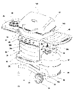
Figure 1 is a perspective view of a barbeque with a side burner and a fuel
tank according
to an embodiment of the present invention;
Figure 2 is a perspective view of a portion of the underside of the barbeque
of Figure 1
showing the underside of the side burner;
Figure 3 is a perspective view of a fuel conduit for the side burner of the
barbeque of
Figure 1;
Figure 4 is an enlarged perspective view of the fuel conduit of Figure 3,
additionally
illustrating an air sleeve thereof;
Figure 5 is a partially isolated view of a valve associated with the side
burner of the
barbeque of Figure 1;
Figure 6 is an assembled view of the valve of Figure 5 and the fuel conduit
and air sleeve
of Figure 4 for the barbeque of Figure l;
21170453.2 _ ( _
CA 02435868 2003-07-23
Agent Ref: 42502/49
Figure 7 is an enlarged underside perspective view of a fuel conduit and the
side burner
of the barbeque in Figure 1;
Figure 8 is an isolated perspective view of the side burner of the barbeque of
Figure l;
Figure 9 is an isolated perspective view of a burner mount end of a fuel
conduit for the
side burner of Figure 3 of the barbeque of Figure 1;
Figure 10 is a perspective view of the barbeque of Figure 1 with the fuel tank
removed to
show a base of the barbeque;
Figure 11 is an isolated top perspective view of the base of the barbeque of
Figure 10;
Figure 12 is an isolated bottom perspective bottom view of the base of Figure
11;
Figure 13 is an isolated rear left side view of an attachf;d support member
and base of the
barbeque of Figure 1;
Figure 14 is an enlarged bottom left perspective view of an attached support
and base of
the barbeque of Figure 1;
Figure 14A is an isolated perspective view of a fastener for mounting a base
to a support
of the barbeque of Figure 1;
Figure 14B is a detailed perspective view of part of an alternative
arrangement for
attaching a leg to a base of the barbeque of Figure 1.
Figure I S is an enlarged bottom right perspective view of an attached wheel
and base of
the barbeque of Figure 1;
Figure 16 is an isolated top perspective view of a receptacle of the barbeque
of Figure l;
Figure 17 is an isolated top rear perspective view of the .receptacle of
Figure 16;
21170453.2 _ 7 _
CA 02435868 2003-07-23
Agent Ref: 42502/49
Figure 18 is an isolated top perspective view of a receptacle of Figure 16 and
panel of
Figure 17;
Figure 19 is an isolated rear perspective view of the receptacle and panel of
Figure 18;
Figure 20 is a perspective view of the barbeque of Figure 1 with a hood
removed showing
a grill therein;
Figure 21 is an isolated perspective view of the grill of the barbeque of
Figure 20;
Figure 22 is an isolated side view of the grill of Figure 21;
Figure 23 is side view of a bridging member and fasteners of the barbeque of
Figure 1
wherein a number of elements of the barbeque have been removed for clarity;
Figure 24 is an opposing side view of an alternative embodiment of the
bridging member
and fasteners of Figure 23;
Figure 25 is an isolated top right perspective view of the bridging member and
fasteners of
Figure 24;
Figure 26 is an isolated top left perspective view of the bridging member of
Figure 24; and
Figure 27 is an isolated view of the fasteners of Figures 23 and 24.
DETAILED DESCRIPTION OF ILLITSTRATIVE EMBODIMENTS OF TIIE
INVENTION
In the figures, similar references are used in different figures to denote
similar
components. Referring to Figures I ; 2 and 10, aspects of a barbeque grill
assembly 20 are
shown. Assembly 20 includes a grill housing 22 which is mounted to a barbeque
housing
21170453.2 _ g _
CA 02435868 2003-07-23
Agent Ref: 42502/49
support structure 24. The barbeque support housing structure includes one or
more supports,
such as legs 26a, 26b, 26c, and 26d (collectively xeferred to as supports 26;
support 26d is shown
in Figure 2). Supports 26a and 26b, and supports 26c and 26d, respectively,
each are bridged, or
braced, by cross pieces 28 and 29, respectively. Cross pieces 28 and 29 also
support grill
housing 22.
Supports 26 are further stabilised by a brace in the natl~re of base 30,
mounted
therebetween. Base 30 may be used to support a fuel storage container such as
a liquid propane
tank 32. Tank 32 rests in tank support area 33 of base 30. Movement of tank 32
is inhibited by
retainer 34. A fuel line 36 is located between tank 32 and valves 38a, 38b,
and 38c (collectively
referred to as valves 38). Valves 38 are preferably used to regulate flow of
fuel carried in fuel
line 36 to grill housing 22 and side burner 40. Valves 38 are mounted to a
console 42, which is
attached to respective ends of cross pieces 28 and 29. A fuel conduit 44, in
the nature of a
venturi conduit, directs the flow of fuel from valve 38a to side burner 40,
which is located in a
side burner shelf 46. A second burner shelf may be included in barbeque grill
assembly 20.
Alternatively, a shelf 48 may be employed, as shown in Figure 1.
Further stabilisation of barbeque housing support structure 24 may be obtained
by
mounting a panel 50 between supports 26. For example, panel 50 may be mounted
between
supports 26a and 26c. A receptacle 52 for holding condiments, for example, may
be mounted to
the barbeque housing support structure 24. Receptacle 52 conveniently co-
operates with
panel 50 when it is mounted adjacent thereto to inhibit lateral movement of
items such as
condiments supported by receptacle 52.
Wheels 54 are preferably be added to barbeque housing support structure 24 to
facilitate
22170453.2 _ 9 _
__.. _.____ __. . .__.~.. , ,_e.< ,.~,~e ~.-,-,~4.. ~~_~...~.r~___~r~~ ~ --
,~~~.._ .___..._.__._.__._.._____.
CA 02435868 2003-07-23
Agent Ref: 42502/49
movement of barbeque grill assembly 20 to alternate locations,
Referring to Figure 2, fuel conduit 44 spans valve 38a and burner 40.
Referring
additionally to Figure 3, fuel conduit 44, may have one or more angles or
bends, such as bend 55
therein. These bends or angles portions permit a fuel source mount end 56 to
align with valve 38
(or some other fuel source), and a burner mount end 58 to align with burner
40. The particular
location of any bends or curves is dependent upon the geometry of an
associated fuel inlet and
burner. For example, if valve 38a and burner 40 were linearly aligned, then
fuel conduit 44 may
be straight, having no bends 55.
Referring to Figure 4, fuel source mount end 56 has an air intake 62 adjacent
thereto to
permit mixing of fuel with external ambient oxygen. Air intake 62 has an air
sleeve 64
associated therewith. Air sleeve 64 has a number of perforations 65 for
permitting the passage of
external ambient air and inhibiting the passage of undesirable harticul.ate,
such as insects. Fuel
source mount end 56 includes a fitting assembly 66. Fitting assembly 66 is
used to rigidly mount
fuel conduit 44 to valve 38a so that burner mount end 58 is located to provide
fuel to burner 40.
Fitting assembly 66 includes a retainer in the nature of a nut 67. Nut 67 has
an internal diameter
dimensioned to cooperate with fuel source mount end 56 enabling nut 67 to be
slidingly engaged
with fuel source mount end 56, and to be rotatable relative thereto so that it
may engage
cooperating threads therein.
To manufacture fitting assembly 66, nut 67 is slid over fuel source mount end
56 and an
inhibitor 68 is applied to inhibit removal of nut 67 from fuel source mount
end ~6, while
permitting at least rotational movement thereof As shown in Figure 4, the
inhibitor is in the
nature of a flared end 68 of fuel source mount end 56. Flared end 68 abuts an
internal rim 69 of
21170453.2 ° 1 p
CA 02435868 2003-07-23
Agent Ref 42502/49
nut 67 to inhibit the removal of nut 67.
Referring to Figures 4 and 5, valve 38a has an outlet 70 defined by a male
feature or spud
72 for insertion into an inlet 71 of conduit 44. Spud 72, while not essential,
serves to inhibit
movement of conduit 44 relative thereto. Outlet 70 also has a complimentary
fitting to co-
operate with fitting assembly 66 to mount conduit 44 to valve 38a. This
fitting may be in the
nature of female threads 74 about outlet 70 for engaging threads of nut 67.
Referring to Figure 6, to install conduit 44, outlet 70 and inlet 7I are
aligned and nut 67 is
tightened over female thread 74. I~lut 67 may be knurled or have some other
feature for
facilitating manual or hand tightening thereof.
Referring to Figures 7 to 9, burner mount end 58 abuts and is retained to
burner inlet 75
to permit fuel to pass between conduit 44 and burner 40. Burner 40 is mounted
to shelf 46 by a
mounting feature in the nature of a burner mount 76. Burner mount 76 may
include a stud or
post 78, which is welded or otherv,~ise attached to a base 82 of burner 40. A
portion of post 78
may be inserted through a hole defined in shelf 46. Once inserted, the portion
is held in place by
a retainer, such as nut 80.
More particularly, referring to Figures 8 and 9, to inhibit fuel From escaping
from the
interface between burner mount end 58 and inlet 75, burner mount end 58 may be
dimensioned
to fit within the interior perimeter of burner inlet 75. This permits burner
mount end 58 to be
inserted therein. To mount burner mount end 58 to burner 40, a feature in the
nature of a
protrusion or flange 86 is crimped, welded or otherwise attached to burner 40.
In a preferred
method for attaching burner mound end 58 to burner 40, burner mount end 58 is
inserted into
burner inlet 75. End 58 is then preferably flared to make a flange such as
flange 86, and crimped
2moas3.a - 11 -
CA 02435868 2003-07-23
Agent Ref: 42502/49
to a base portion 82 of burner 40. A cup portion 84 of burner 40 is then
crimped or otherwise
mounted to burner base 82, the cup 84 and base 82 co-operating to form burner
40. Burner
mount 76 thus secures end 58 of fuel conduit 44 via burner base 82. Flange 86
may be added to,
or formed integrally with, fuel conduit 44.
Burner mount end 58 may be configured to have a shape, such as a non-round
shape, and
burner inlet 75 may be correspondingly dimensioned, so that rotation of burner
mount end ~8
within burner inlet 75 is further inhibited. For example, mount end 58 and
inlet 75 may have an
n-sided polygonal shape as shown in Figure 9.
Fuel conduit 44 is installed by installing burner 40, ali~ming fuel source
mount end 56
with valve 38a, and tightening retainer 80. ~nce fuel conduit 44 is al'~igned,
nut 67 may be
tightened to secure fuel conduit 44.
Fuel conduit 44 is preferably made of a fire-resistant material, such as a
metal. It is also
rigid so that it may be mechanically retained while maintaining a secure and
direct connection
between a fuel source (or a valve) and a burner. This arrangement permits the
convenient
location of valve 38a on console 42, instead of on shelf 46. Additional tubing
is therefore not
required to connect valve 38a to either the console or fuel tank. 32. Fuel
conduit 44 is also
secured at both ends, which permits it to span a greater distance to burner 40
than if it were
merely in abutting relationship with valve 38a, as bs the state of the prior
art. The described
arrangement also attempts to reduce the number of connections and parts
required to provide fuel
to a burner from a fuel source (or valve). In the present embodiment., only
one connection needs
to be made when mounting fuel conduit 44 to barbeque grill 20.
It will be appreciated that the particular fittings described in the present
embodiment such
21170453.2 - 12
CA 02435868 2003-07-23
Agent Ref: 42502/49
as fitting assembly 66, may have connection fittings, such as the malt; and
female parts reversed.
For example, nut 67 could be included on a flared outlet similar to outlet 70,
for attachment to a
threaded fuel source mount end similar to fuel source mount end 56. ~ther
connection
arrangements may also be used.
Now, aspects of a base of the barbeque 24 are illustrated. Ilelrerring to
Figures 10 to 12, a
brace in the nature of a base 30 is mounted between at least two, and
preferably all, supports 26.
Base 30 has a fuel container or tank support area 33 for supporting a portion
of a fuel storage
container 32. Support area 33 is pl°eferably generally planar, having a
feature, such as a
protrusion 90, for abutting tank 32 to inhibit lateral movement thereof.
Further, support area 33
is planar, but it may be angled do~Tnward towards the middle of base 30.
Protrusion 90 is
preferably configured to abut a lower rim 92 of container 32 (Figure 1) or
other feature of
container 32. As is best shown in Figure 1 l, protrusion 90 comforms to a fit
against an exterior
portion of lower rim 92 and abuts lower rim 92 when it is placed thereagainst.
An additional
protrusion in the nature of a locating nub 94 may be added to, or integral
with, base 30. Locating
nub 94 is preferably spaced from protrusion 90 by at least a thickness of
lower rim 92. Lower
rim 92 then may be placed between locating nub 94 and protrusion 90 to inhibit
lateral
movement thereof. While nub 94 may be formed in base 30, for example by
stamping, it is
manufactured as a separate piece in the present embodiment. As shown, nub 94
has a head and a
shaft. The shaft is inserted into a hole defined in base 30, and is maintained
in place by a retainer
(e.g., a nut) or in some other manner.
Tank support area 33 is preferably located at an end of base 30. When tank 32
is
mounted therein, tank 32 is located at a fixed, spaced distance from grill
housing 22 (which
contains at least one burner element; not shown) and side burner 40. This
arrangement serves to
211'70453.2 _ 13
CA 02435868 2003-07-23
Agent Ref: 42502/49
comply with the safety regulations of some jurisdictions, which mandate that a
fuel source and a
burner of a barbeque grill assembly be located at specific spaced distance to
each other. Further,
the location of tank 32 in tank support area 33 is encouraged by a pre:Eerred
orientation of base 30
when it is mounted to supports 26. As shown in Figures 1 and 10, base 30 is
preferably mounted
so that it is generally laterally inclined relative to the grill housing, and
consequently, relative to
the ground. When base 30 is so mounted, support area 33 will be les s offset
from ground level.
Such a preferred orientation is further encouraged by having rr~ounting holes
108 and 112
arranged in a plane which is slightly offset from vertical in a direction away
from support area
33. This inclined assembly discourages placement of fuel storage container 32
in an area other
than in tank support area 33, because an alternative generally Level surface
is not provided in
base 30 for supporting fuel tank container 32. The generally inclined
orientation of base 30 may
also provide increased lateral support to barbeque rotating support stricture
24.
Base 30 is made of a single generally rigid piece of material. 'This rigidity
can serve to
stabilise any barbeque assembly components attached thereto, such as supports
26. While base
30 may be moulded from a plastic or other material, it is preferably stamped
from a single sheet
of metal such as a deep drawn or double deep drawn cold rolled steel.
To increase the rigidity of the sheet, raised areas or deformations such as
embossments
96 may be added or stamped therein. To increase longitudinal rigidity, raised
portions 96
preferably extend centrally and longitudinally of the base 30. l~,ateral
reinforcement may also be
obtained by including raised portions in a non-longitudinal direction. In the
present
embodiment, raised portions 96 extend longitudinally and then merge into a
generally arcuate
shape to both reinforce tank support area 33, and to define protrusion 90.
raised portions may
additionally be tapered or ramped to further increase rigidity of base 30.
Additional
2117043.2 - 14 -
CA 02435868 2003-07-23
Agent Ref: 42502/49
reinforcement may be obtained, and material may be saved, by constructing base
30 to have one
or more non-linear, and preferably inwardly arcuate, sides 98a and 98b.
Further strengthening of
base 33 may be obtained by including a rib or flange, such as flange 102.
While flange 102 may
be added to base 30, it is preferably stamped integrally therewith to reduce
the need for welds in
the barbeque grill assembly 20. Flange 102 is preferably located adjacent a
perimeter of base 30,
and preferably extends about the entire perimeter of base 30.
Now, further detail is provided on mounting arrangements of base 30. Referring
additionally to Figures 13 to 15, base 30 may be mounted to supports 26 using
one or more
fasteners 104, located adjacent tank support area 33, and one or more
fasteners 106 located
adjacent an end of base 30, generally opposite to tank support area 33. While
base 30 may be
attached to supports 26 by welding or some other permanent ataachmE;nt, a
releasable fastener is
preferably used so that barbeque grill assembly 20 may be conveniently
packaged disassembled,
to reduce packaging required, and then assembled and disassembled a.s needed.
Fastener 104 may include a bolt, such as a carriage bolt, and a retainer in
the nature of a
wing nut. Fastener 104 is preferably configured for manual or hand tightening.
Flange 102 has
at least one hole 108 for receiving fastener 104. Similarly, an associated
support, such as support
26b, defines at least one hole 109 for receiving fastener 104 as well. ~fhe
bolt is inserted through
holes 108 and 109, and is retained by the wing nut. A pronged spacer 111 may
be used to inhibit
rotation of support 26 relative to base 30. Pronged spacer 111 has dowel-like
protrusions 113
(see Figure 14A) projecting therefrom. These protl-usions 113 are received by
holes such as
holes 109 and 108 of support 26 and base 30, respectively. As the wing nut of
fastener 104 is
tightened, protrusions 113 are held in place in both holes 109 and 108 to
inhibit shearing
21170453.2 - 15 _
CA 02435868 2003-07-23
Agent Ref 42502/49
movement of support 26 relative to base 30.
Fastener 104 may alternatively be a wing bolt having tlhree prongs (not shown)
therein.
The three prongs would be inserted through holes 109 and 108 with the middle
prong being
retained by a wing nut, for example. Base 30 or support 26 could alternatively
have integral or
extruded protrusions, similar to protrusions 113. An example of such.
protrusions are labelled
I I3' in Figure 14B. To assemble base 30 to support 26, the protrusions are
inserted through
holes 109 and 108, with a carriage bolt and wing nut securing 'the connection.
Referring in particular to Figure 14, fastener 106 is used to mount base 30 to
a different
support 26 in a similar manner as described for fastener 104. Fastener 106 is
preferably
configured for manual or hand tightening. Holes 115 located in support 26 are
positioned to
encourage base 30 to be inclined, as described above. At least one of holes
115, such as hole
115a, may be non-round to inhibit rotational movement of a similarly
configured retainer. Holes
109 and 115 may be included in thf: same support member 26 so that the support
member may be
used to mount either end of base 30 thereto. This configuration permits
multiple uses for a
support.
As best shown in Figure l5, fastener 104 may also be used to retain a wheel 54
to the
barbeque housing support structure 24. It should be appreciated that
additional holes 108 and
109 may be added to base 30 and supports 26 to enable base 30 to be attached
to supports 26 at
different locations as may be needed for a particular installation of barbeque
grill assembly 20.
The arrangement described above can reduce the munber of welds required to
manufacture barbeque grill assembly 20, because base 30 may be stamped from a
single sheet of
material. The use of removable fasteners, such as fasteners 104 and 106,
permits barbeque grill
2a mods~.2 - 16
CA 02435868 2003-07-23
Agent Ref: 42502/49
assembly 20 to be shipped in unassembled form, which may reduce the amount of
packaging
required for shipping.
Turning now to Figure 16, details of a receptable for barbeque 20 are
provided. As
shown, receptacle 52 has a portion in the nature of bottom 116 for supporting
items stored
therein. Receptacle 52 also has three sides 118 which co-operate with bottom
116 to form a
four-sided partial enclosure. Sides 118 could be formed as one continuous side
in the shape of
an arc or some other shape that would cooperate with bottom 116 to create a
partial enclosure.
Sides 118 terminate at free edges 120. Similarly, bottom 116 terminates at a
free edge 122
thereof. Bottom free edge 122 may additional include a flange 138 for
providing rigidity to
bottom 116 and for providing support to clip 134.
As best seen in Figures 17 and 18, side edges 120 and bottom 116 together
define an
opening in the shape of a portion of panel 50. As best shown in Figure 18,
when receptacle 52
and panel 50 are aligned with panel 52 located to abut bottom 116 and to span
free edges 120,
then bottom I 16, sides 118, and front panel 50 cooperate to form a five-sided
partially enclosed
container, shelf or rack for the convenient storage of items such as
condiments and barbeque grill
accessories (not shown). In this configuration, sides 118 and panel 50
together define the
boundary of an opening 123 which provides access for placement and removal of
items in
receptacle 52. It will be appreciated that the particular shape of the
receptacle is not limited to
the present embodiment. Other shapes that are convenient for the storage of
barbeque-related
items may also be used. For example, a receptacle having one continuous,
generally spherical
side, forming an enclosure and having an opening, could also be used, with
panel 50 completing
the side thereof. Sides 1 I 8 may further be provided with a rim 124 for added
strength about
21170453.2 _ I'~ "
CA 02435868 2003-07-23
Agent Ref: 42502/49
opening 123.
Panel 50 is preferably generally planar and serves to stabilize barbeque
housing support
structure 24. Panel 50 is mounted between adjacent supports 26, and may be
made of plastic,
metal or some other appropriate material.
Mounts 126 for receptacle 52 are provided adj scent free terminal edges 120.
Mounts 126
cooperate with a fastener which may be in the nature of a carriage bolt
assembly 130, that is also
used to attach panel 50 to supports 26. The fastener is preferably configured
for manual or hand
tightening. In this configuration, the same fasteney-s are used t~o mount both
front panel 50 and
receptacle 52, which can help to reduce the number of parts required for
barbeque grill assembly
20. This co-operation between panel 50 and receptacle 52 permits receptacle 52
to be added to
or removed from barbeque assembly 20, as needed. For example, one model of
barbeque
assembly produced by a manufacturer could include a receptacle 52, while
another model may
not. Since the configuration and mounting of the panel 50 is essentially the
same in either case,
only one version of panel 50 would need to be manufactured for both models of
barbeque
assembly. Furthermore, the same carriage bolt assembly 130 that is used to
mount panel 50 to
barbeque assembly 20 can be used to optionally mount receptacle 52, as well.
Mount 126 may include a flange 128. Flange 128 may be angled to conform to an
exterior of shape of support 26. Support 26 may be any convenient shape,
having a cross-
section, for example, that is round or rectangular. In the present embodiment,
supports 26 have a
rectangular cross-section. Accordingly, flange 128 has a right angle formed
therein for abutting
support 26. Carriage bolt 130 is inserted through a hole (not shown) in flange
128. It is then
inserted through a hole passing through support 26 (not shownl, and a hole
defined in front panel
21170453.2 _ 1 g
CA 02435868 2003-07-23
Agent Ref 42502/49
50 (not shown). Carriage bolt 130 is held in place by a retainer, which may be
in the nature of a
wing nut 132. When wing nut 132 is tightened to carriage bolt 130, then flange
128, support 26,
and panel 50 are mounted to one another. Mount 126 may additionally include a
clip 134 to
further retain receptacle 52 to support 26. Clip 134 may be configured as a
resilient finger
having a toe 136 for engaging a portion of support 26. In the preferred
embodiment, angled
flange 128 abuts two sides of support 26, and clip 134 abuts the other two
sides of support 26 so
that at least a portion of each side of support 26 is retained by the combined
clip 134 and flange
128.
Receptacle 52 is preferably made as a unitary molded product. For example, it
may be
injection molded from a resilient plastic. Any resiliency in the plastic
material can permit free
ends of angled flange 128 and clip 134 to be manually bent away from one
another to permit
support 26 to be located therebetween prior to carriage bolt 130 being
installed. Alternatively,
receptacle 52 could be made as a metal part or welded or otherwise assembled
from a series of
some sub-components to achieve the functions described above.
The above-described cooperation between receptacle 52 and panel 50 permits
receptacle
52 to be included with barbeque grill assembly 20 as an optional feature.
Unlike receptacles
known in the art, which tend to be constructed integrally with an associated
panel, the structural
functionality of panel 52 is not lost by the removal of receptacle 52.
Now referring to Figure 20, aspects of a grill housing fir barbeque 20 are
provided. As
shown, grill housing 22 has upper grill housing or hood 140 removed to reveal
grill 141 (hood
140 is illustrated in Figures 1 and I0). Grill 141 is mountable to lower grill
housing 143, having
a burner or other heat source located therein (not shown). Grill 141 relay be
mounted to lower
21170453.2 - 19 -
CA 02435868 2003-07-23
Agent Ref: 42502/49
grill housing 143 in a manner known in the art. For example grill 141 may be
supported by a
ledge or tabs (not shown) of lower grill housing 143 and may be held in place
by gravity or
friction.
Referring additionally to Figures 21 and 22, grill 141 includes a cooking
surface 142 and
a warming rack 146, cantilevered thereto. Cooking surface 142 is made of a
series of connected
rods 144, but may alternatively be made of any material in a configuration
that permits the
transfer of heat from a heat source located within lower grill housing 143 to
food items which are
supported by cooking surface 142. For example, grill 141 could be made from a
single sheet of
metal, which may additionally have perforations therein (not shown). In the
preferred
embodiment, metal rods 144 made of cold rolled steel are preferably parallel
and evenly spaced,
to form cooking surface 142. Rods 144 are preferably interconnected by one or
more transverse
rods 145 attached thereto. Transverse rods 145 may be connected by welding or
in any other
suitable manner known in the art.
Grill 141 includes warming rack 146. Warming rack 146 pref erably is
interconnected to
cooking surface 142. Both cooking surface 142 and warming rack 146 are
preferably co-planar
so that they can support food products to be cooked or warmed. Cooking surface
142 and
warming rack 146 are preferably generally opposed to one another and are
generally parallel to
one another. While warming rack 146 may have the same area as cooking surface
142 (provided
that its size does not prevent hood 140 from closing), warming rack 146 is
preferably smaller in
area than cooking surface 142. This arrangement permits access to food
products being cooked
or warmed on cooking surface 142. Fox example, if warming rack 146 and cooking
surface 142
were opposed and had the same area, then it could be difficult to access or
tum food products
21174453.2 - 20 -
CA 02435868 2003-07-23
Agent Ref: 42502!49
located on cooking surface 142.
Warming rack 146 is connected to cooking surface 142 via riser 148. As shown,
riser
148 comprises a series of bars linking bars of cooking surface 142 with
corresponding bars of
warming rack 146. Riser 148 may be integral with cooking surface 142 and
warming rack 146.
For example, riser 148 may be mounted between cooking surface 142 and warming
rack 146. In
the preferred embodiment, riser 148, cooking surface 142 and warming rack 146
are integrally
formed.
The combined cooking surface 142, riser 148, and warming rack 146, preferably
together
have a generally U-shaped or J-shaped profile (see Figure 22). ThesE;
components may
alternatively have some other convenient profile such as a C-shaped or a more
arcuate shape.
Alternatively, riser 148 may be stepped or have some ather configuration that
maintains warming
rack 146 at a distance from cooking surface 142. This displacement attempts to
reduce the
amount of heat provided to food supported by warming rack 146 compared to food
located in
lower grill housing 143.
Grill 141 is preferably made from a generally planar unitary piece having
transverse rods
145 at either end thereof. The unitary piece then has at least two bends 150
and 152 formed
therein. Bends 150 and 152 may each form internal angles of 90 degrees. In the
preferred
embodiment, bend 150 has an acute internal angle and bend 152 has an obtuse
internal angle so
that warming rack 146 is generally parallel and opposed to cooking sl:lrface
142. Additional
bends may be provided, as long as warming rack 146 is not too skewed relative
to cooking
surface 142 to cause food products to slide or otherwise fall the;refrom.. In
an alternative
embodiment (not shown), a single arcuate bend may be formed in a sheet of
interconnected rods
21170453.2 _ 21 --
CA 02435868 2003-07-23
Agent Ref: 42502/49
so that the grill has an arcuate C-shape or J-shape. A third bend 154,
adjacent bend 152 may be
included to inhibit food from rolling off warming surface 146, particularly
when food is removed
using a spatula. Third bend 154 also acts as a spring to increase stability
and encourage resilient
bending at bend 154.
It will be appreciated that the dimensions of warming rack 146 are determined
by the
number and length of rods 144 used. Rods 144 can include shorter rods 156 and
longer rods 158.
For example, in the preferred embodiment, four rods 156 located to either side
of the rods 158
(which are used to form warming rack 146) are shorter in length and only form
part of cooking
surface 142. The combination of rods 156 and 158 can be used to determine the
area of warming
rack 146. Similarly, if rods longer than rods 158 are employed, then warming
rack can have a
greater area.
Alternatively, the height of riser 148 can be adjusted b:y forming bend 152 at
a different
location. A longer riser 148 can be expected to reduce the heating of food
products supported on
warming rack 146, because warming rack 146 will be further from the heat
source located in
lower grill housing 143. In any embodiment or variation desca~ibed herein, the
materials used for
constructing grill I41 may be enamelled with porcelain.
Now referring to Figures 23 and 24, detail on a cross piece of barbeque 20 is
provided.
As shown, a cross piece or bridging member 29 spans legs 26d and 2fic and
inhibits movement
thereof. Cross member 29 also supports grill housing 22, and console 42 (as
seen in Figure 1).
Cross member 28 (Figure 24) is similar in function and configuration to cross
member 29, but it
differs in that it additionally supports slideable retainer 34 for tank 32.,
Cross member 28 also
differs in that it does not include a rebate such as rebate 160 of cross
member 29. A rebate, such
21170453.2 _ 22
CA 02435868 2003-07-23
Agent Ref: 42502/49
as rebate 160, may be added to a cross member to facilitate the location of
other components of
the barbeque assembly 20, such as conduit 44 (see Figure 2 for example).
Rebate 160 may be
stamped from cross member 129, and is preferably rounded, or has a flange, to
temper any sharp
edge remaining after the formation of rebate 160.
Referring to Figures 25 and 26, cross piece 28 is shown in isolation. Please
note that the
description provided herein for cross piece 28 applies mutatis mutandis to
cross piece 29, except
as otherwise noted.
Cross piece 28 includes a generally planar body 162, having at least one hole
163 defined
therein. Hole 163 receives fastener 164 for attachment to a feature
of'barbeque assembly 20.
Fastener 164 is a bolt 166 having ribs 168 comprising longitudinal fins
radially projecting in a
spaced relationship from the shaft of bolt 166 and located about the base of
bolt 168. In the
preferred embodiment, bolt 166 is a 1/4-20 rib neck bolt having 11, 12 or 13
ribs. However,
larger or smaller bolts having a greater or fewer number of rib: may also be
used as appropriate.
Hole 163 is sized to have a diameter similar to that of bolt 166 (not
including ribs 168). Bolt 166
is press fit to body 162. This is accomplished by inserting a free end 172 of
bolt 166 into hole
163 until further insertion is inhibited by ribs 168. At this point, greater
force is applied to the
head 172 of bolt 166 to force ribs 168 to deform edges of hole 163 so that
ribs 168 bite, grip, or
are otherwise engaged with, the edge of hole 163. Bolt head 172 inhibits
further insertion of bolt
166 into hole 163. Removal of bolt 166, or rotation thereof, is inhibited by
the engagement of
ribs 168 with the edges of hole 163. It is expected that consumers would not
assemble bolt 166
to body 162 due to the added force required to insert bolt 166 and engage body
162. Instead,
these two components would be preassembled. Bolt 166 may be alternatively
mounted to cross
piece 28 by welding (not shown). For example, a stud or bolt having point on
its head may be
21170453.2 - 23
CA 02435868 2003-07-23
Agent Ref: 42502/49
projection welded to crass piece 28 about the points.
Once bolt 166 is retained within hole 163, a componer~l: of barbeque assembly
20 may be
mounted to bolt free end 170, and may be retained by a retainer such as a
manually tightenable
nut 174. Nut 174 is threaded onto bolt 170. Figure 27 provides an isolated
view of fastener 164,
including bolt 166 and retainer I74. It should be noted that various
fasteners, including fastener
164, are shown in Figures 25 and 26. They each are preferably configured for
manual or hand
tightening. Some of the fasteners are shown without their associated
retainers, and some
fasteners are shown having retainers mounted thereon. However, no components
of barbeque
assembly 20 are shown mounted by fasteners to cross piece 28 to more clearly
illustrate cross
piece 28 and its associated fasteners in situ. In assembled fornn, cross piece
28 would have
components mounted thereto with retainers installed.
Referring to Figures 25 and 26, cross piece 28 includes a flange I76 formed in
body 162.
Flange 176 orients fastener 164 to a desired orientation, and can be used to
impart rigidity to
body 162. One or more indents or dimples 178 may also be included along an
interface or bend
179, which defines flange 176 in body 162.
Fastener 164 may be used to mount lower grill housing 143 to cross piece 28.
This is
accomplished by inserting free end I70 of bolt 166 into a corresponding hole
(not shown)
defined in lower grill housing I43. Once inserted, free end I70 is retained by
nut I74, which is
attached thereto. Lower grill housing 143 may be further retained and mounted
to cross piece 28
using one or more additional fasteners, such as fastener 180, having a
configuration similar to
that described for fastener 164.
Additional components of gas barbeque assembly 20 may also be attached to
cross piece
21170453.2 _ 24,
CA 02435868 2003-07-23
Agent Ref: 42502/49
28. For example, a fastener 181 may be used to slideably engage tank retainer
34 (see figure 24).
A transverse indent 182 may be included in body :162 to further reinforce body
162 and to
provide a guide for tank retainer 34 as it is moved between engaged and
disengaged positions
(not shown) with a top of tank 32.
Body 162 of cross piece 28 may also include a flange X183 for engaging and
supporting
console 42. Flange 183 preferably has a similar profile to that of an interior
surface of console
42 (not shown) so that there is limited play between console 42 and flange 183
when console 42
is mounted thereon. Due to the similar profile, flange 183 can act as a side
of console 42. A
ridge 190 in flange 183 provides an abutting surface for an edge of flange 183
to further assist in
locating console 42 upon flange 183.
A fastener 186 (illustrated in isolation in Figure 27) is used to secure
console 42 to cross
piece 28. Fastener 186 includes a retainer or nut 187 mounted to flange 183.
Nut 187 may be
mounted by welding, for example, and is centered about a hole (not shown)
defined by flange
183. Fastener 186 also includes a bolt 192 for insertion through a hole
defined in console 42 and
retention by nut 187. Bolt 192 is configured to be manually tightenable. For
example, it may
have a knurled surface to facilitate the gripping thereof.
In the preferred embodiment, cross member 28 spans and stabilizes supports 26a
and 26b.
Cross piece 28 is mounted at both ends to supports 26a and 26b, respectively,
by employing
fasteners 194 and 196. Fasteners 194 and 196 are configured and provide a
similar function as
described for fastener 164. For example, a bolt 198 of fastener 194 is mounted
to cross piece 28
as described above. Support 26a may then be mounted thereto by inserting a
free end of bolt 198
into a hole defined through support 26a (not shown). Free end 200 is then
engaged by a retainer
21 no4s3.2 - 25
CA 02435868 2003-07-23
Agent Ref: 42502/49
202 of fastener 194, and tightened to mount support 26a to cross piece 28.
Support 26b is
similarly mounted to cross piece 28. It should be Doted that body 162 may
alternatively be
welded to supports 26a and 26b respectively. However, cross piece 28 is
preferably mounted to
supports 26a and 26b in the manner described above so that supports 26a and
26b and cross
piece 28 may be disassembled, and therefore packaged or stored in a smaller
volume.
Cross piece 28 may additionally include one or more tabs 204. Tabs 204 may be
attached
to or integrally formed in body 162. For example, tabs 204 may be stamped and
bent from body
162. Tabs 204 are located and positioned to abut supports 26a. and 26b to
encourage a preferred
alignment of supports 26a and 26b relative to cross piece 28 when they are
mounted to cross
piece 28.
Body 162 may be made from any substantially rigid material, such as metal cold
rolled
steel. The area about the interface between the fasteners and cross piece 28
may be deformed to
form bosses 206. Bosses 206 provide a greater land area to for the fastener
ribs to grip cross
piece 28. Bosses 206 also create a clearance for the fastener ribs so that
when a fastener is
tightened, it is more difficult for the ribs to go through a thickness of
cross piece 28.
As will be noted from the above description, cross piece 28 permits the
convenient
manual attachment of various components of barbeque assembly 20, without
requiring any
welds. This can serve to reduce the cost of manufacturing such an assembly,
and permits
baxbeque assembly 20 to be stored, shipped, or packaged in a smaller volume.
By including the
various fasteners such as fastener 164, as part of cross piece 28, generally
fewer loose pieces are
included in the disassembled barbeque 20, and fewer pieces need to be
assembled by a consumer
when putting barbeque assembly 20 together.
21170453.2 - 26
CA 02435868 2003-07-23
Agent Ref: 42502/49
It will be understood by those skilled in the art that this description is
made with
reference to the illustrative embodiments and methods, and that it is possible
to make other
embodiments and to make use of other methods, while employing the principles
of the invention
which fall within the spirit and scope thereof. For example, various
embodiments of a barbeque
of the present invention may include different combinations of the embodiments
of the
component parts thereof.
27170453.2 _ 27