Note: Descriptions are shown in the official language in which they were submitted.
B&P File No. 8494-14
BERESKIN & PARR CANADA
Title: DEFECTIVE SOD REJECTOR AND
DEFLECTOR
Inventor(s): Gerardus J. Brouwer and Robert
Milwain
CA 02435934 2003-07-23
-1-
Title: Defective Sod Rejector and Deflector
FIELD OF THE INVENTION
[0001] This invention relates to sod harvestors. More particularly, it
relates to sod harvesters which cut strips of sod and form the cut strips into
rolls.
BACKGROUND OF THE INVENTION
[0002] Automatic sod harvesters which cut a strip of sod from a field of
sod, and then form the cut strip into discrete rolls of sod, have been well
known since the late 1960's. More recently, there has been a trend to
providing mechanisms which can receive and store a number of sod rolls, and
which can then transfer the stored rolls onto a pallet. An example of such a
mechanism is shown in U.S. patent 4,966,239 to Hutchison.
[0003] In sod harvesters which contain a storage area for a number of
sod rolls, for transfer of the stored rolls to a pallet, it is important to
reject
defective sod rolls and pieces of scrap sod before they reach the storage
area. If a defective sod roll or piece reaches the storage area, it typically
abuts tightly against or may be sandwiched between other sod rolls, making
the defective roll very difficult to remove at this stage. If the defective
roll is
transferred from the storage area to a pallet, it becomes even more difficult
to
remove, since it will be surrounded by other sod rolls which are not
defective.
[0004] If the defective sod roll is removed before it reaches the sod roll
storage area, then a problem arises with how to dispose of the defective roll.
It is not practical to store the defective rolls on the harvester, since space
there is limited. If a defective roll is disposed of on the ground, it may
interfere
with subsequent passes of the sod harvester.
CA 02435934 2003-07-23
-2-
BRIEF SUMMARY OF THE INVENTION
[0005] It is therefore an object of the invention, in one of its aspects, to
provide a sod harvester adapted for travel along a path of travel in a sod
field,
said harvester having:
(a) a cutting head for producing cut sod from said field and thereby
producing a cut area in said field, and for leaving in said field an
uncut area from which sod has not yet been cut;
(b) a conveyor assembly behind said cutting head for conveying cut
sod from said cutting head;
(c) a roll-up mechanism associated with said conveyor assembly for
forming said cut sod into a plurality of sod rolls;
(d) a sod roll storage receiver adjacent said conveyor assembly for
receiving a plurality of said sod rolls;
(e) a diverter mechanism between said conveyor assembly and
said storage receiver and moveable between a first position in
which said diverter mechanism allows sod to travel from said
conveyor assembly to said storage receiver, and a second
position in which said diverter diverts sod to be rejected away
from said storage receiver; and
(f) a deflector for deflecting said sod to be rejected away from said
uncut area and onto said cut area in a position such that sod
which has been rejected will not interfere with the next pass of
said harvester.
[0006] In another aspect, the invention provides a method of
harvesting sod in a sod field with a harvester having a cutting head and
wheels, said method comprising:
CA 02435934 2003-07-23
-3-
(a) cutting a strip of said sod and forming said strip into a roll,
leaving a cut portion in said field;
(b) conveying said roll onto a storage receiver;
(c) causing a defective piece of sod to fall through a gap before it
reaches said storage receiver; and
(d) deflecting said defective piece of sod onto the cut portion of
said field in a position in which said defective piece of sod will
not interfere with said cutting head or wheels on the next pass
of said harvester.
(0007 Further objects and advantages of the invention will appear from
the following description, taken together with the accompanying drawings, in
which:
Fig. 1 is a perspective view of a typical prior art sod harvester;
Fig. 2(a) to 2(d) are views of a defective sod roll rejector and
deflector of the invention;
Fig. 3 is a top plan view of a sod harvester according to the
invention and located in a sod field being cut, showing the positioning of a
rejected sod roll;
Figs. 4(a) to 4(d) are views of another embodiment of a
defective sod roll rejector and deflector according to the invention;
Figs. 5(a) to 5(d) are views of another embodiment of a
defective sod roll rejector and deflector according to the invention;
Figs. 6(a) to 6(d) are views of another embodiment of a
defective sod roll rejector and deflector according to the invention; and
CA 02435934 2003-07-23
-4-
Figs. 7(a) to 7(d) are views of another embodiment of a
defective sod roll rejector and deflector according to the invention.
DETAILED DESCRIPTION OF PREFERRED EMBODIMENTS
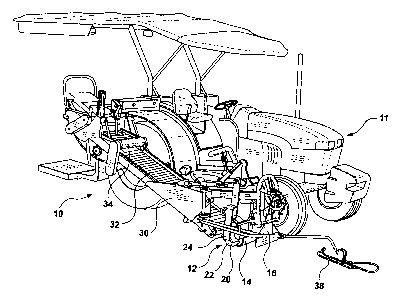
[0008] Sod harvesters may be attached to a tractor for propulsion, or
may be self-propelled. Fig. 1 illustrates a typical prior art sod harvester 10
such as that produced by the present applicant, Kesmac Inc. of Keswick,
Ontario, Canada, for attachment to a tractor 11. However, the invention is
equally applicable to a self-propelled sod harvester, such as that shown in
U.S. patent 4,966,239.
[0009] The sod harvester 10 includes a cutting head 12 containing a
conventional ground roller 14 located behind a conventional cross cut blade
16. The cross cut blade 16 is driven downwardly at periodic intervals (by a
conventional mechanism 18) to form a transverse cut in the ground, so that
the strip of sod which is to be cut by the cutting head 12 will be cut in
lengths,
each of which can be formed into a roll.
(0010] The strip of sod to be cut travels beneath the roller 14 and is
then undercut by a conventional undercutting knife 20, which includes side
cutting blades 22, one at each side thereof. The undercutting knife 20 is
mounted on arms 24 which are reciprocated forwardly and rearwardly in
conventional fashion by a hydraulic motor (not shown), to cut a strip of sod.
[0011] The cutting head 12 is mounted on a conveyor frame 30 which
extends rearwardly from the cutting head. A main conveyor 32 is mounted in
the conveyor frame 30 and carries cut sod rearwardly and upwardly from the
undercutting knife 20, to a sod roll-up mechanism (in the prior art harvester
shown) 34 where the sod is rolled. The sod rolls are then delivered (in the
prior art harvester shown) to a location where the operator can manually place
the roll on a pallet (not shown) carried by the harvester.
[0012] The harvester 10 is automatically steered or guided by an auto-
steer shoe 38, which follows the cut edge of the sod in the field being cut
and
CA 02435934 2003-07-23
-5-
actuates the hydraulic steering mechanism of the tractor 11. This is well-
known in the industry.
[0013] Figs. 2(a), 2(b), 2(c) and 2(d) show diagrammatically a
mechanism for use on a sod harvester in which the sod rolls are as mentioned
accumulated in a group for delivery to a pallet. As shown, the sod rolls 36
are
delivered by the main conveyor 32 to a storage conveyor 40, similar to the
arrangement shown in U.S. patent 4,966,239. (The main conveyor 32 and
storage conveyor 40 are located on a sod harvester which for clarity is not
shown in Figs. 2(a) to 2(d)). When the desired number of sod rolls, shown
here as five rolls, have been accumulated as a set on storage conveyor 40,
they are lifted and moved by a sod clamp 42 to a pallet (not shown).
(0014] Once a sod roll 36 reaches the storage conveyor 40, such roll
can be difficult to remove from that location, since it abuts tightly with at
least
one adjacent roll and may be sandwiched between two adjacent roils, one on
each side. Therefore, defective sod rolls (also called scrap) should be
removed before they reach the storage conveyor 40.
[0015] In the Figs. 2(a) to (2(d) arrangement, this is accomplished by
locating the rear end of the storage conveyor 40 on a pivot 44, and mounting
the storage conveyor 40 on the piston rod 46 of a hydraulic cylinder 48. The
cylinder 48 is pivoted at 50 to the conveyor frame 30, while the piston rod is
pivoted at 52 to a frame 54 of the storage conveyor 40.
(0016] With the arrangement thus described, if the operator observes
defective sod coming up the main conveyor 32 or a defective sod roll being
formed by the roll-up mechanism 34, then the operator actuates cylinder 48
(by a control, not shown) to tilt the storage conveyor 40 upwardly as shown in
Fig. 2(c). This forms a gap 60 between the end 40a of the storage conveyor
40 and the main conveyor 32, allowing the defective sod roll, shown at 62, to
fall through such gap.
[0017] An important feature of the invention is that the rejected and
defective roll of sod should not be allowed to interfere with subsequent
passes
CA 02435934 2003-07-23
-6-
of the harvester. As shown in Fig. 3, the harvester 10 travels forwardly along
a path of travel 64 in a sod field 66. As the harvester cuts sod and as the
sod
is rolled up and placed on pallets, the field 66 becomes divided into a cut
area
68 (from which the sod has been removed) and an uncut area 70 (from which
the sod has not yet been cut). Then two areas are divided by a cut sod edge
72 (which the auto-steer shoe 38 tracks). It is a feature of this invention
that
the rejected sod roll 62 falls onto the cut area 68, and not onto the uncut
area
70. In addition, the rejected sod roll 62 falls onto the cut area 68 in a
location
such that it will not be run over by the tractor 11 wheels, or interfere with
the
auto-steer shoe 38, on the next pass of the tractor 11.
[0018] To ensure that the rejected sod roll 62 does not interfere with
the tractor wheels at the very time when the rejected sod roll falls to the
ground, the gap 60 is positioned behind the tractor rear wheels (one of which
is shown in dotted outline at 74 in Fig. 2(b)). However, to ensure that the
rejected roll 62 does not interfere with the next pass of the harvester and
tractor, the rejected roll 62 is dropped to the ground in a position such that
it
will be between the tractor wheels on the next pass of the tractor (and
therefore will not be run over by the tractor).
[0019] This positioning of the rejected sod roll 62 in the proper location
on the cut area 68 is accomplished by a deflector 76, which as shown in Figs.
2(a) to 2(d) and 3 comprises a metal sheet mounted below the end of the
main conveyor 32, to receive rejected rolls which fall through the gap 60. The
deflector 76 has a sloped upper surface 78, sloping downwardly and inwardly
towards the cut area 68, to deflect the rejected roll of sod onto the cut area
68.
[0020] When the harvester 10 is attached to a tractor 11 (and is not
self-propelled), the dimensions and location of the deflector 76 must be made
such that as mentioned, the rejected roll 62 will be between the tractor
wheels
in the next pass. If for example the width of sod roll being cut is 16 inches,
and the width of the path (or "footprint") of the front and rear tractor
wheels
adjacent the harvester 10 (including any offset between the wheels), indicated
CA 02435934 2003-07-23
-7-
by dimension D in Fig. 3, is 14 inches, then deflector 76 must deliver
rejected
roll 62 to a location which is at least 14 inches away from the cut sod edge
72,
but which will be between the tractor wheels (which are usually three to four
feet apart). This situation is illustrated in Fig. 3, where the tractor on its
next
pass is shown at 11 a, and a rejected sod roll which has been deflected by
deflector 76 is shown at 62a. It will be seen that rejected roll 62a lies on
the
cut area 68, between the tractor wheels.
[0021] If the sod harvester is self-propelled, as shown in U.S. patent
4,966,239, then the same principles apply, i.e., the deflector 76 is located
and
dimensioned to place the defective roll 62 on the cut area where it will be
out
of the path of the cutting head on the next pass of the machine, and so that
roll 62 will also be out of the way of the wheels of the harvester if the
wheels
overlap onto the cut area 68 on the next pass.
[0022] Reference is next made to Figs. 4(a) to 4(d), which show
another embodiment of a defective sod roll rejector. In the Figs. 4(a) to 4(d)
arrangement, in which corresponding reference numerals indicate
corresponding parts, the hydraulic cylinder 48 for supporting the storage
conveyor 40 has been replaced by a fixed mounting 82, and an intermediate
conveyor 84 has been positioned between the rear end of the main conveyor
32 and the front end of the storage conveyor 40. The front end of the
intermediate conveyor 84 is mounted on a pivot (the details of which are not
shown). The rear of intermediate conveyor 84 is mounted on the piston rod
86 of a cylinder 88. As best shown in Fig. 4(c), when the piston rod 86 is
withdrawn into the cylinder 88, the rear end of the intermediate conveyor 84
pivots downwardly, discharging a rejected roll or piece of sod 62 onto the
deflector 76 for placement on the proper location in the cut area 68. As
before, it will be seen that the deflector 76 is positioned below the gap 60
through which the rejected sod roll or piece 62 drops when the intermediate
conveyor 84 is pivoted downwardly.
CA 02435934 2003-07-23
- $ -
[0023] The intermediate conveyor 84 can be driven by frictional
engagement with main conveyor 32, or alternatively it may have a separate
drive motor (not shown).
[0024] Reference is next made to Figs. 5(a) to 5(d), which show
another embodiment of the invention. Again, parts corresponding to those in
Figs. 1 to 4 have been given corresponding reference numerals. In Fig. 5, the
intermediate conveyor 84 does not pivot, but instead is mounted at the top
end of a vertically oriented piston rod 90 extending from a vertically
oriented
cylinder 92 mounted on the harvester 10. In the position shown in Figs. 5(a)
and 5(b), the intermediate conveyor 84 forms a bridge between the rear end
of the main conveyor 84 and the front end of the storage conveyor 40,
permitting sod rolls formed by the roll-up mechanism 34 to be delivered to the
storage conveyor 40. The intermediate conveyor 54 may be driven by a
separate hydraulic motor or other drive mechanism (not shown).
[0025] When scrap sod is to be rejected, the piston rod 90 is retracted,
moving the intermediate conveyor 89 downwardly to the position shown in
Fig. 5(c) and leaving a gap 60 between the main and storage conveyors 32,
40. The sod 62 to be rejected falls through the gap 60 onto the lowered
intermediate conveyor 84. Because the intermediate conveyor 84 is driven,
the scrap sod 62 is carried to the rear end of the intermediate conveyor 84
and is then discharged onto the deflector 76, which causes the scrap sod to
be deposited onto the cut area 68 in the desired position (as explained
previously).
(0026] Another embodiment of the invention is shown in Figs. 6(a) to
6(d), in which like reference numerals indicate corresponding parts. In Figs
6(a) to 6(d), the storage conveyor 40 is oriented at right angles to the main
conveyor 32. An intermediate conveyor 89 (driven by a hydraulic motor or
other means not shown) is located between the main and storage conveyors
32, 40. The intermediate conveyor 84 is also oriented at right angles to the
main conveyor 32 and is located end-to-end with the storage conveyor 40.
The intermediate conveyor 84 receives formed sod rolls from the main
CA 02435934 2003-07-23
_g_
conveyor 32 and delivers them axially (i.e., they are transported in a
direction
parallel to their axis) onto the storage conveyor 40.
[0027] When a defective sod roll or other scrap sod 62 is to be
discarded in the Fig. 6 arrangement, then the intermediate conveyor 84 is
pivoted as shown in Fig. 6(b), i.e., the far end 94 of the intermediate
conveyor
84 (with respect to the storage conveyor 40) is pivotally mounted so that the
end 96 of the intermediate conveyor 84 which is normally adjacent the storage
conveyor 40 can be pivoted downwardly as shown. (The pivotting is powered
by a hydraulic cylinder, not shown.) This forms a gap 60 between the main
and storage conveyors 32, 40, through which scrap sod can be discarded. A
deflector 76 positioned below the gap 60 deflects the scrap sod 62 onto the
cut area 68 in the proper position as previously described.
[0028] Another embodiment of the invention is shown in Figs. 7(a) to
7(d), in which like parts have been given corresponding reference numerals.
In Figs. 7(a) to 7(d), the intermediate conveyor 84 has been replaced by a
pivoting end section 100 on the main conveyor 32. The pivoting end section
100 is formed by providing appropriate pivot points in the rear rollers of the
main conveyor 32. Any desired means (usually a hydraulic cylinder) may be
used to actuate the pivoting of end section 100.
[0029] When a sod roll is to be rejected, the pivoting end section 100 is
pivoted downwardly as shown in Fig. 7(c). The scrap sod 62 to be rejected,
instead of being delivered onto the storage conveyor 40 is then discharged
onto the deflector 76, from which it is deflected onto the cut portion 68 in
the
desired position.
[0030] While preferred embodiments of the invention have been
described, it will be appreciated that changes can be made within the scope of
the invention.