Language selection

Search

Patent 2436002 Summary

Third-party information liability

Some of the information on this Web page has been provided by external sources. The Government of Canada is not responsible for the accuracy, reliability or currency of the information supplied by external sources. Users wishing to rely upon this information should consult directly with the source of the information. Content provided by external sources is not subject to official languages, privacy and accessibility requirements.

Claims and Abstract availability

Any discrepancies in the text and image of the Claims and Abstract are due to differing posting times. Text of the Claims and Abstract are posted:

  • At the time the application is open to public inspection;
  • At the time of issue of the patent (grant).
(12) Patent: (11) CA 2436002
(54) English Title: TORQUE DISCONNECT MECHANISM
(54) French Title: MECANISME DE DEBRAYAGE
Status: Expired and beyond the Period of Reversal
Bibliographic Data
(51) International Patent Classification (IPC):
  • F16H 57/00 (2012.01)
  • F16D 11/04 (2006.01)
  • F16H 63/04 (2006.01)
(72) Inventors :
  • ORE, THOMAS G. (United States of America)
  • JOHNSON, PAUL W. (United States of America)
  • GOGOLA, JOHN C. (United States of America)
(73) Owners :
  • DEERE & COMPANY
(71) Applicants :
  • DEERE & COMPANY (United States of America)
(74) Agent: BORDEN LADNER GERVAIS LLP
(74) Associate agent:
(45) Issued: 2007-07-10
(22) Filed Date: 2003-07-25
(41) Open to Public Inspection: 2004-02-12
Examination requested: 2003-07-25
Availability of licence: N/A
Dedicated to the Public: N/A
(25) Language of filing: English

Patent Cooperation Treaty (PCT): No

(30) Application Priority Data:
Application No. Country/Territory Date
10/217,298 (United States of America) 2002-08-12

Abstracts

English Abstract


A torque disconnect mechanism controls transmission of torque from a first
shaft to a second shaft in a transmission. The mechanism includes a housing
which
rotatably supports the first and second shafts, and which has an opening
formed
therein. A coupling member is movable from an engaged position wherein the
coupling member couples the first shaft with the second shaft to a disengaged
position wherein the first and second shafts are uncoupled from each other. A
plug
member is mountable in the opening and is engagable with the coupling member.
The plug member is movable from a first position holding the coupling member
in its
engaged position to a second position holding the coupling member in its
disengaged position.


Claims

Note: Claims are shown in the official language in which they were submitted.

CLAIMS:
1. A torque disconnect mechanism for controlling transmission of torque from
a first shaft to a second shaft in a transmission, comprising:
a housing rotatably supporting the first and second shafts, the housing
having an opening formed therein;
a coupling member being movable from an engaged position wherein the
coupling member couples the first shaft with the second shaft to a disengaged
position wherein the first and second shafts are uncoupled from each other;
and
a plug member mountable in the opening and engagable with the coupling
member, the plug member being movable from a first position holding the
coupling member in its engaged position to a second position holding the
coupling
member in its disengaged position, the plug member comprising a cylindrical
head receivable in the opening, and a tab projecting from the head, the tab
being
engagable with the coupling member, and the tab being offset from a central
axis
of the head.
2. The torque disconnect mechanism of claim 1, wherein:
the coupling member is a hollow annular member which receives one of
the shafts.
3. The torque disconnect mechanism of claim 1, wherein:
a drive gear is rotatably mounted on the first shaft, the drive gear having a
first set of drive splines which meshingly engage corresponding splines on the
second shaft, and having a second set of drive splines;
a hub gear is mounted on the first shaft and is fixed for rotation with the
first shaft, the hub gear having a set of hub splines formed thereon; and
the coupling member comprises an annular collar engagable with the drive
gear and with the hub gear, the collar having an annular groove which receives
the tab of the plug member.
4

4. The torque disconnect mechanism of claim 1, wherein:
a drive gear is rotatably mounted on the first shaft, the drive gear having a
first set of drive splines which meshingly engage corresponding splines on the
second shaft, and having a second set of drive splines;
a hub gear is mounted on the first shaft and is fixed for rotation with the
first shaft, the hub gear having a set of hub splines formed thereon; and
the coupling member comprises a hollow annular member having a first set
of inner splines and a second set of inner splines spaced axially away from
the
first set of inner splines, an annular groove between the first and second set
of
inner splines, an outer surface of the annular member forming a first land and
a
second land separated by radially outwardly opening annular groove, the first
set
of inner splines meshing with the second set of drive splines, and the second
set
of inner splines being selectively meshable with the hub splines.
5. A torque disconnect mechanism for controlling transmission of torque from
a first shaft to a second shaft in a transmission, comprising:
a drive gear rotatably mounted on the first shaft and having a first set of
drive splines which meshingly engage corresponding splines on the second
shaft,
and having a second set of drive splines;
a hub gear fixed for rotation with the first shaft and having a set of hub
splines formed thereon;
a coupling member engagable with the drive gear and with the hub gear,
the coupling member being movable from an engaged position wherein the
coupling member couples the hub splines with the second set of drive splines
to a
disengaged position wherein the hub splines are uncoupled from the second set
of drive splines, the coupling member comprises a hollow annular member having
a first set of inner splines and a second set of inner splines spaced axially
away
from the first set of inner splines, an outer surface of the annular member
forming
a first land and a second land separated by radially outwardly opening annular
groove, the first set of inner splines meshing with the second set of drive
splines,
and the second set of inner splines being selectively meshable with the hub
splines; and

a plug member engagable with the coupling member, the plug member
being movable from a first position holding the coupling member in its engaged
position to a second position holding the coupling member in its disengaged
position.
6. The torque disconnect mechanism of claim 5, wherein:
the coupling member includes a radially inwardly opening annular groove
between the first and second set of inner splines, said annular groove
receiving
the second set of splines of the drive gear when the coupling member is in its
disengaged position.
7. The torque disconnect mechanism of claim 5, wherein:
the plug includes a tool-receiving aperture in an outer surface thereof.
8. A torque disconnect mechanism for controlling transmission of torque from
a first shaft to a second shaft in a transmission, comprising:
a housing rotatably supporting the first and second shafts, the housing
having an opening formed therein;
a coupling member being movable from an engaged position wherein the
coupling member couples the first shaft with the second shaft to a disengaged
position wherein the first and second shafts are uncoupled from each other;
a plug member mountable in the opening and engagable with the coupling
member, the plug member being movable from a first position holding the
coupling member in its engaged position to a second position holding the
coupling
member in its disengaged position;
a drive gear is rotatably mounted on the first shaft, the drive gear having a
first set of drive splines which meshingly engage corresponding splines on the
second shaft, and having a second set of drive splines;
a hub gear is mounted on the first shaft and is fixed for rotation with the
first shaft, the hub gear having a set of hub splines formed thereon; and
6

the coupling member comprises an annular collar engagable with the drive
gear and selectively engagable with the hub gear, the collar having an annular
groove which receives the plug member.
9. A torque disconnect mechanism for controlling transmission of torque from
a first shaft to a second shaft in a transmission, comprising:
a housing rotatably supporting the first and second shafts, the housing
having an opening formed therein;
a coupling member being movable from an engaged position wherein the
coupling member couples the first shaft with the second shaft to a disengaged
position wherein the first and second shafts are uncoupled from each other;
a plug member mountable in the opening and engagable with the coupling
member, the plug member being movable from a first position holding the
coupling member in its engaged position to a second position holding the
coupling
member in its disengaged position, the plug including a tool-receiving
aperture in
an outer surface thereof.
7

Description

Note: Descriptions are shown in the official language in which they were submitted.


CA 02436002 2003-07-25
TORQUE DISCONNECT MECHANISM
BACKGROUND OF THE INVENTION
The present invention relates to a mechanism for coupling and uncoupling
components of a transmission and controlling the transmission of torque
therebetween.
When servicing or diagnosing a transmission it is desirable to disconnect
the transmission output shaft and prevent torque from being transmitted to the
output shaft. A transmission on a production John Deere tractor includes a
sliding
collar which couples and uncouples a pair of gears which transmit torque from
a
planetary transmission shaft to the transmission output shaft. A pivoting
shift fork is
coupled between the collar and an arm which extends outside the transmission.
A
long release rod extends to the rear of the tractor and engages a spring-
loaded
bracket. Because of tolerance stackup it is possible for the fork to rub on
the collar
during normal operation, and the parts take up space at the rear of the
tractor, yet
these parts are rarely used.
SUMMARY
Accordingly, an object of this invention is to provide a simpler torque
disconnect device with fewer parts.
These and other objects are achieved by the present invention, wherein a
torque disconnect mechanism controls transmission of torque from a first shaft
to a
second shaft in a transmission. The torque disconnect mechanism includes a
drive
gear rotatably mounted on the first shaft. The drive gear has a first set of
drive
splines which meshingly engage corresponding splines on the second shaft, and
a
second set of drive splines. A hub gear is fixed for rotation with the first
shaft and
includes a set of hub splines. A coupling member is engagable with the drive
gear
and with the hub gear, and is movable from an engaged position wherein the
coupling member couples the hub splines with the second set of drive splines
to a
disengaged position wherein the hub splines are uncoupled from the second set
of
drive splines. A plug member is mounted in a housing opening and is engagable
with the coupling member. The plug member is movable from a first position
holding
the coupling member in its engaged position to a second position holding the
coupling member in its disengaged position.

CA 02436002 2003-07-25
BRIEF DESCRIPTION OF THE DRAWINGS
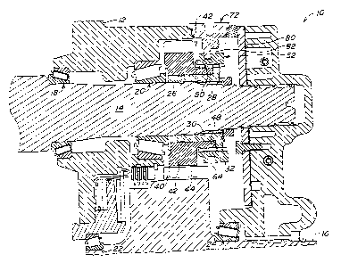
Fig. 1 is a simplified sectional view of the present invention in a torque
transmitting position;
Fig. 2 is a view similar to Fig. 1, but showing the present invention in a
torque-disconnect position;
Fig. 3 is a partial sectional view of the collar of Fig. 1;
Fig. 4 is a perspective view of the collar of Fig. 1;
Fig. 5 is a perspective view of the plug of Fig. 1;
Fig. 6 is a top view of the plug of Fig. 1;
Fig. 7 is a sectional view along lines 7-7 of Fig. 6; and
Fig. 8 is a sectional view along lines 8-8 of Fig. 6.
DETAILED DESCRIPTION
Fig. 1 shows a portion of a transmission 10 which includes a housing 12
which rotatably supports a shaft 14 and a shaft 16. Shaft 14 may be a
planetary
output shaft and shaft 16 may be a transmission output shaft. Shaft 14 is
supported
by bearings 18 and 20, while shaft 16 is supported by bearings 22 and 24. A
hollow
hub gear 26 is mounted on shaft 14. Gear 26 includes inner splines 28 which
engage outer splines 30 on the shaft 14. Gear 26 also includes outer splines
32.
A drive gear 40 is rotatably mounted on a portion of the hub gear 26. Drive
gear 40 includes a large diameter part 42 on which are formed splines 44.
Splines
44 engage corresponding splines 46 on shaft 16. Drive gear 40 also includes a
smaller diameter part 48 on which are formed splines 50 which are axially
adjacent
to splines 32 of hub gear 26.
An annular collar 52 is mounted over the splines 50 and 32. As best seen
in Fig. 3, collar 52 has a generally cylindrical body with a pair of axially
spaced apart
sets of splines 54 and 56 separated by an radially inwardly opening annular
groove
58. The outer surface of the collar 52 forms a pair of lands 60 and 62
separated by
an outer annular groove 64. As best seen in Fig. 4, a plurality of teeth 63
may be
formed on land 62 for use with a standard magnetic speed sensor (not shown).
2

CA 02436002 2003-07-25
Referring to Figs. 1 and 2, housing 12 has an opening 70 formed therein. A
service disconnect plug 72 is removably mounted in the opening 70. As best
seen in
Figs. 4-7, plug 72 has a generally cylindrical head portion 74 in which are
formed a
pair grooves 76 and 78 for receiving O-ring seals. A central cylindrical shaft
80
projects axially away from head 74. A tab 82 projects axially away from one
side of
the end surface of shaft 80. A threaded central blind bore 84 extends into an
outer
surface of the head 74 for receiving a threaded tool (not shown) for use in
manipulating the plug 72. As best seen in Fig. 5, textual instructional labels
may be
printed on the end surface of the head 74 to guide an operator in orienting
the plug
72 in the opening 70. As best seen in Figs. 4, 5 and 7, a pair of partial
circular
cutouts 86 and 88 are formed in a radial outer peripheral surface of the head
74. As
best seen in Fig. 6, the tab 82 is offset from, or positioned entirely on one
side of a
central axis 90 of the head 74.
With the plug 72 oriented in opening 70 as shown in Fig. 1, the tab 82
extends from the left side of the shaft 80 into groove 64 of the collar 52.
This holds
collar 52 in its engaged position wherein splines 54 and 56 are in meshing
engagement with splines 50 and 32, respectively, and torque can be transmitted
from shaft 14 to shaft 16.
To disengage shaft 14 from shaft 16, the plug 72 is removed from opening
70 and a tool (not shown) is inserted through opening 70 and into grove 64,
and the
tool is then manipulated to slide collar 52 to the right into the disengaged
position
shown in Fig. 2. The plug 72 is then preferably re-oriented so that the tab 82
is
oriented to the right, and then plug 72 is re-inserted back into opening 70 so
that tab
82 is received by groove 64. Tab 82 thereby holds collar 52 in its disengaged
position wherein splines 56 are uncoupled from splines 32 and torque cannot be
transmitted from shaft 14 to shaft 16.
While the present invention has been described in conjunction with a
specific embodiment, it is understood that many alternatives, modifications
and
variations will be apparent to those skilled in the art in light of the
foregoing
description. Accordingly, this invention is intended to embrace all such
alternatives,
modifications and variations which fall within the spirit and scope of the
claims.
3

Representative Drawing
A single figure which represents the drawing illustrating the invention.
Administrative Status

2024-08-01:As part of the Next Generation Patents (NGP) transition, the Canadian Patents Database (CPD) now contains a more detailed Event History, which replicates the Event Log of our new back-office solution.

Please note that "Inactive:" events refers to events no longer in use in our new back-office solution.

For a clearer understanding of the status of the application/patent presented on this page, the site Disclaimer , as well as the definitions for Patent , Event History , Maintenance Fee  and Payment History  should be consulted.

Event History

Description Date
Inactive: IPC deactivated 2016-03-12
Inactive: First IPC assigned 2016-01-08
Inactive: IPC assigned 2016-01-08
Inactive: IPC expired 2012-01-01
Time Limit for Reversal Expired 2008-07-25
Letter Sent 2007-07-25
Grant by Issuance 2007-07-10
Inactive: Cover page published 2007-07-09
Pre-grant 2007-04-17
Inactive: Final fee received 2007-04-17
Notice of Allowance is Issued 2006-10-19
Letter Sent 2006-10-19
Notice of Allowance is Issued 2006-10-19
Inactive: IPC removed 2006-08-30
Inactive: IPC assigned 2006-08-30
Inactive: Approved for allowance (AFA) 2006-08-21
Amendment Received - Voluntary Amendment 2006-07-13
Inactive: IPC from MCD 2006-03-12
Inactive: S.29 Rules - Examiner requisition 2006-01-17
Inactive: S.30(2) Rules - Examiner requisition 2006-01-17
Application Published (Open to Public Inspection) 2004-02-12
Inactive: Cover page published 2004-02-11
Inactive: First IPC assigned 2003-09-30
Inactive: Filing certificate - RFE (English) 2003-09-02
Filing Requirements Determined Compliant 2003-09-02
Letter Sent 2003-09-02
Application Received - Regular National 2003-09-02
Request for Examination Requirements Determined Compliant 2003-07-25
All Requirements for Examination Determined Compliant 2003-07-25

Abandonment History

There is no abandonment history.

Maintenance Fee

The last payment was received on 2006-07-13

Note : If the full payment has not been received on or before the date indicated, a further fee may be required which may be one of the following

  • the reinstatement fee;
  • the late payment fee; or
  • additional fee to reverse deemed expiry.

Please refer to the CIPO Patent Fees web page to see all current fee amounts.

Fee History

Fee Type Anniversary Year Due Date Paid Date
Registration of a document 2003-07-25
Application fee - standard 2003-07-25
Request for examination - standard 2003-07-25
MF (application, 2nd anniv.) - standard 02 2005-07-25 2005-07-06
MF (application, 3rd anniv.) - standard 03 2006-07-25 2006-07-13
Final fee - standard 2007-04-17
Owners on Record

Note: Records showing the ownership history in alphabetical order.

Current Owners on Record
DEERE & COMPANY
Past Owners on Record
JOHN C. GOGOLA
PAUL W. JOHNSON
THOMAS G. ORE
Past Owners that do not appear in the "Owners on Record" listing will appear in other documentation within the application.
Documents

To view selected files, please enter reCAPTCHA code :


To view images, click a link in the Document Description column. To download the documents, select one or more checkboxes in the first column and then click the "Download Selected in PDF format (Zip Archive)" or the "Download Selected as Single PDF" button.

List of published and non-published patent-specific documents on the CPD .

If you have any difficulty accessing content, you can call the Client Service Centre at 1-866-997-1936 or send them an e-mail at CIPO Client Service Centre.


Document
Description 
Date
(yyyy-mm-dd) 
Number of pages   Size of Image (KB) 
Description 2003-07-25 3 152
Abstract 2003-07-25 1 19
Drawings 2003-07-25 4 173
Claims 2003-07-25 3 130
Representative drawing 2003-10-01 1 36
Cover Page 2004-01-23 1 65
Claims 2006-07-13 4 158
Cover Page 2007-06-27 1 67
Acknowledgement of Request for Examination 2003-09-02 1 173
Courtesy - Certificate of registration (related document(s)) 2003-09-02 1 106
Filing Certificate (English) 2003-09-02 1 160
Reminder of maintenance fee due 2005-03-30 1 111
Commissioner's Notice - Application Found Allowable 2006-10-19 1 161
Maintenance Fee Notice 2007-09-05 1 174
Correspondence 2007-04-17 1 33