Language selection

Search

Patent 2436060 Summary

Third-party information liability

Some of the information on this Web page has been provided by external sources. The Government of Canada is not responsible for the accuracy, reliability or currency of the information supplied by external sources. Users wishing to rely upon this information should consult directly with the source of the information. Content provided by external sources is not subject to official languages, privacy and accessibility requirements.

Claims and Abstract availability

Any discrepancies in the text and image of the Claims and Abstract are due to differing posting times. Text of the Claims and Abstract are posted:

  • At the time the application is open to public inspection;
  • At the time of issue of the patent (grant).
(12) Patent: (11) CA 2436060
(54) English Title: LOCKUP ASSEMBLY FOR A PLANTING UNIT
(54) French Title: SYSTEME DE BLOCAGE POUR DISPOSITIF DE PLANTATION
Status: Expired and beyond the Period of Reversal
Bibliographic Data
(51) International Patent Classification (IPC):
  • A01C 07/00 (2006.01)
  • A01B 63/00 (2006.01)
  • A01B 63/26 (2006.01)
  • A01C 07/20 (2006.01)
  • A01C 15/00 (2006.01)
(72) Inventors :
  • MARIMAN, NATHAN ALBERT (United States of America)
  • STOEHR, RANDALL WILLIAM (United States of America)
(73) Owners :
  • DEERE & COMPANY
(71) Applicants :
  • DEERE & COMPANY (United States of America)
(74) Agent: BORDEN LADNER GERVAIS LLP
(74) Associate agent:
(45) Issued: 2006-07-18
(22) Filed Date: 2003-07-28
(41) Open to Public Inspection: 2004-02-14
Examination requested: 2003-07-28
Availability of licence: N/A
Dedicated to the Public: N/A
(25) Language of filing: English

Patent Cooperation Treaty (PCT): No

(30) Application Priority Data:
Application No. Country/Territory Date
10/218,646 (United States of America) 2002-08-14

Abstracts

English Abstract


A planting unit lockup assembly extends between upper and lower links of a
parallelogram linkage. A lockup link is pivotally coupled to the upper link
and
extends downwardly to the lower link. The lockup link is also provided with a
slot
having a hook. A slide member is mounted to the lower link and engages the
slot.
A control link is pivotally coupled to the lockup link by a loose pivot
coupling. The
control link is biased towards the lower link by a spring. The control link is
provided
with a trapping element that engages the lockup link. The trapping element of
the
control link engages the lockup link in one of two positions, a normal
position and a
lockup position. In its normal position, the control link biases the hook away
from the
slide bushing member. In its lockup position, the control link biases the hook
toward
the slide bushing member.


Claims

Note: Claims are shown in the official language in which they were submitted.

Claims
1. A planting unit lockup assembly for a planting unit having a parallelogram
linkage being provided with an upper link and a lower link, the lockup
assembly
comprising:
a lockup link extending between the upper link and the lower link, the lockup
link being pivotally mounted to the upper link, the lockup link having a hook;
the lower link having a member that bears against the lockup link;
a control link is pivotally coupled to the lockup link, the control link being
biased towards the lower link by a spring, the control link having two
positions for
engaging the lockup link, a normal position whereby the control link biases
the hook
of the lockup link away from the member and a lockup position whereby the
control
link biases hook of the lockup link towards the member.
2. A planting unit lockup assembly as defined by claim 1 wherein lockup link
is provided with a slot in which the member is inserted, the slot defining the
hook.
3. A planting unit lockup assembly as defined by claim 2 wherein the control
link is provided what trapping element that engages the lockup link.
4. A planting unit lockup assembly as defined by claim 3 wherein the lockup
link is provided with an aperture into which the trapping element is inserted
when the
control link is in its normal position.
5. A planting unit lockup assembly as defined by claim 4 wherein the control
link is loosely pivotally coupled to the lockup link.
6. A planting unit lockup assembly as defined by claim 5 wherein the control
link is provided with an oblong aperture into which is inserted a cylindrical
bushing
that is mounted to the lockup link, the cylindrical bushing pivotally couples
the control
link to the lockup link.
7. A planting unit lockup assembly as defined by claim 5 wherein the member
is a sliding bushing located in the slot , the sliding bushing being mounted
on the
lower link.
8. A planting unit lockup assembly as defined by claim 5 wherein the trapping
element is provided with a trapping lip.
9. A planting unit lockup assembly as defined by claim 8 comprises a nut that
5

is mounted to a mounting bolt passing through the control link.
10. A planting unit lockup assembly as defined by claim 9 wherein the
mounting bolt is provided with a spacer to define a handle for the control
link.
11. A planting unit lockup assembly as defined by claim 5 wherein the control
link is provided with a handle.
12. A planting unit lockup assembly, for a planting unit having parallelogram
linkage having right and left parallelogram linkages, one of the parallelogram
linkages being provided with an upper link and a lower link, the lockup
assembly
comprising:
a lockup link extending between the upper link and the lower link, the lockup
link being pivotally mounted to the upper link, the lockup link having a hook,
the
lockup link being located between the right and left parallelogram linkages;
the lower link having a member that bears against the lockup link;
a control link is pivotally coupled to the lockup link, the control link
having two
positions for engaging the lockup link, a normal position whereby the control
link
biases the hook of the lockup link away from the member and a lockup position
whereby the control link biases hook of the lockup link towards the member.
13. A planting unit lockup assembly as defined by claim 12 wherein lockup
link is provided with a J-shaped slot in which the member is inserted, the J-
shaped
slot defining the hook.
14. A planting unit lockup assembly as defined by claim 13 wherein the
control link is provided with a trapping element that engages the lockup link.
15. A planting unit lockup assembly as defined by claim 14 wherein the
lockup link is provided with an aperture into which the trapping element is
inserted
when the control link is in its normal position.
16. A planting unit lockup assembly as defined by claim 15 wherein the
control link is loosely pivotally coupled to the lockup link.
17. A planting unit lockup assembly as defined by claim 16 wherein the
control link is provided with an oblong aperture into which is inserted a
cylindrical
bushing that is mounted to the lockup link, the cylindrical bushing pivotally
couples
the control link to the lockup link.
6

18. A planting unit lockup assembly as defined by claim 16 wherein the
member is a sliding bushing located in the slot , the sliding bushing being
mounted
on the lower link.
19. A planting unit lockup assembly as defined by claim 16 wherein the
trapping element is provided with a trapping lip.
20. A planting unit lockup assembly as defined by claim 16 wherein the
control link is provided with a handle that extends outwardly from the
parallelogram
linkages.
7

Description

Note: Descriptions are shown in the official language in which they were submitted.


CA 02436060 2003-07-28
LOCKUP ASSEMBLY FOR A PLANTING UNIT
Field of the Invention
The present invention is directed to a lockup assembly for a planting unit
having a lockup link and a control link, wherein the control link has a normal
position
and a lockup position for engaging the lockup link.
Background of the Invention
Planting units are typically coupled to a toolbar by parallelogram linkages so
that the planting units can move vertically a limited amount relative to the
toolbar.
Sometimes a farmer wishes to deactivate or lockup one or more planting units.
For
example, a farmer with planting units on fifteen-inch rows for soybeans may
want to
switch to thirty-inch rows for corn. The farmer would lockup every other
planting unit
to plant the corn.
Lockup units are well known in the art. One example is disclosed in US
Patent 4,738,317.
Summary of the Invention
It is an object of the present invention to provide a planting unit lockup
assembly that is compact and easy to operator.
The planting unit lockup assembly extends between upper and lower links of
a parallelogram linkage. The lockup assembly comprises a lockup link and a
control
link. The lockup link is pivotally coupled to the upper link and extends
downwardly to
the lower link. The lockup link is also provided with a slot having a hook. A
slide
bushing member is mounted to the lower link and engages the slot. The control
link
is pivotally coupled to the lockup link by a loose pivot coupling. The control
link is
biased towards the lower link by a spring extending from the control link to
the lower
link. The control link is provided with a trapping element that engages the
lockup
link. The trapping element of the control link engages the lockup link in one
of two
positions, a normal position and a lockup position. In the normal position,
the
trapping element engages an aperture located in the lockup link. In its lockup
position, the trapping element engages the side edge of the lockup link. In
its normal
position, the control link through the trapping element biases the hook away
from the
slide bushing member. In its lockup position the control link through the
trapping

CA 02436060 2003-07-28
element biases the hook towards the slide bushing member. The control link is
provided with a handle for switching the control link between the two
positions.
The control link is located between the left and right parallelogram linkages.
Only the handle extends outwardly from the parallelogram linkages. This
reduces the
width requirements for the lockup assembly.
Brief Description of the Drawings
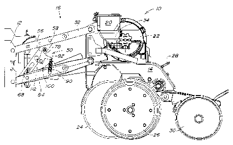
Figure 1 is a side view of the planting unit it in its normal position.
Figure 2 is a side view of the planting unit in its lockup position.
Figure 3 is an exploded view of the lockup assembly.
Detailed Description
The seeding machine 10 comprises an individual row crop planting unit that
is mounted to a transverse toolbar, not shown, by U-bolts that engage a
mounting
plate 12. The planting unit is provided with a frame 14 that is coupled to the
mounting plate 12 by a parallel linkage 16. The parallel linkage 16 allows the
planting unit to move up and down to a limited degree relative to the toolbar.
Seed is
automatically directed to the planter by a pneumatic seed on demand delivery
system. The seed on demand delivery system directs the seed pneumatically from
a
main hopper, not shown, through a seed hose to an auxiliary hopper 20 mounted
on
tame 14. Seed in the auxiliary hopper 20 is metered by a pneumatic pressure
seed
meter 22 and directed to a planting furrow by a seed tube, not shown.
The planting furrow is formed by a double disc furrow opener 24 having
depth gauging wheels 26. The depth of the planting furrow is controlled by the
positioning of handle 28 which controls the vertical position of the depth
gauging
wheels 26 relative to the furrow opener 24. The planting furrow with metered
seed
deposited therein by the seed tube is closed by closing wheels 30.
The seed meter 22 is driven by a flexible rotatable drive shaft, not shown,
that drives gear box 34. The flexible and rotatable drive shaft is of a type
manufactured and marketed by Elliott Manufacturing Company, LLC .of
Binghamton,
New York. A ground driven transmission, not shown, provides a rotational input
into
2

CA 02436060 2003-07-28
the flexible drive shaft. In this way the ground speed of the seeding machine
10
controls the speed of the seed meter 22.
Sometimes a farmer will want to lock one or more planting units into a raised
non-use position. To that end a planting unit lock assembly 50 is mounted to
the
parallel links 16. The parallel links 16 have an upper link 52 and a lower
link 54. A
lockup link 56 extends between the upper and lower links 52 and 54. The lockup
link
56 is pivoted on main pivot 58. The lockup link 56 is provided with a main
pivot
aperture which is aligned with aperture 60 in upper link 52. A bushing 62 is
located
in the main pivot aperture and is secured thereto by main pivot bolt 64,
washer 65
and nut 66. The lockup link 56 is provided with a J-slot 68 having a hook 70.
A slide
bushing 72 rides in the slot 68. The slide bushing is secured thereto by slide
bolt
74, washer 75 and nut 76.
A control link 78 is pivotally mounted to the lockup link 56 by pivot bushings
80 that are mounted to the lockup link 56 by carriage bolt 82, washer 83 and
nut 84.
The carriage bolt 82 is received in square aperture 86 on the lockup link 56.
The
pivot bushings 80 are received into an oblong loose aperture 88. The looseness
of
this aperture 88 relative to the pivot bushings 80 allows the control link 78
to be
pivoted away from the lockup link 56 as will be discussed in more detail
later. The
control link 78 is biased by spring 90 towards the lower link 54. The spring
90 being
hooked onto the arm 92 of the control link 78 and being anchored to the lower
link 54
by pin 94, washer 95 and cotter pin 96.
The control link 78 is also provided with a combined handle and
engagement element 100. The handle portion of the element 100 is formed by
mounting bolt 102 and spacer 104. The mounting bolt 102 passes through the
control link 78, bushing 106 and engages trapping nut 108. The trapping nut
108 is
provided with an outwardly extending trapping lip 110. The mounting bolt 102,
bushing 106 and trapping nut 108 forming the engagement portion of element
100.
The control link 78 as dictated by element 100 has two positions. A normal
position illustrated in Figure 1 and a lockup position illustrated in Figure
2. In its
normal position, the trapping nut 108 of element 100 is located in enlarged
aperture
112. In its normal position, when the planting unit is raised, the spring 90
biases the
3

CA 02436060 2003-07-28
control link 78 counterclockwise. Therefore the engagement portion of the
element
100 pulls lockup link 56 counterclockwise so that the slide bushing 72 bears
against
the edge of the slot 68 away from the hook 70.
In its lockup position the farmer grabs the handle portion of the element 100
an pulls the control link 78 away from the lockup link so that the trapping
nut 108 is
removed from enlarged aperture 112. The trapping nut 108 is then placed behind
the lockup link as illustrated in Figure 2. In this lockup position, when the
planting
unit is raised, the spring 90 biases the control link 78 clockwise. Therefore
the
engagement portion of the element 100 pushes lockup link 56 clockwise so that
the
slide bushing 72 bears against the edge of the slot 68 towards the hook 70.
When
the planting unit reaches its lockup position, the slide bushing 62 engages
the hook
70 trapping the planting unit in the lockup position.
Having described the preferred embodiment, it will become apparent that
various modifications can be made without departing from the scope of the
invention
as defined in the accompanying claims.
4

Representative Drawing
A single figure which represents the drawing illustrating the invention.
Administrative Status

2024-08-01:As part of the Next Generation Patents (NGP) transition, the Canadian Patents Database (CPD) now contains a more detailed Event History, which replicates the Event Log of our new back-office solution.

Please note that "Inactive:" events refers to events no longer in use in our new back-office solution.

For a clearer understanding of the status of the application/patent presented on this page, the site Disclaimer , as well as the definitions for Patent , Event History , Maintenance Fee  and Payment History  should be consulted.

Event History

Description Date
Time Limit for Reversal Expired 2010-07-28
Letter Sent 2009-07-28
Grant by Issuance 2006-07-18
Inactive: Cover page published 2006-07-17
Inactive: Final fee received 2006-05-02
Pre-grant 2006-05-02
Inactive: IPC from MCD 2006-03-12
Notice of Allowance is Issued 2005-11-22
Letter Sent 2005-11-22
Notice of Allowance is Issued 2005-11-22
Inactive: Approved for allowance (AFA) 2005-11-10
Application Published (Open to Public Inspection) 2004-02-14
Inactive: Cover page published 2004-02-13
Inactive: IPC assigned 2003-09-26
Inactive: First IPC assigned 2003-09-26
Inactive: Filing certificate - RFE (English) 2003-09-04
Letter Sent 2003-09-04
Letter Sent 2003-09-02
Application Received - Regular National 2003-09-02
Request for Examination Requirements Determined Compliant 2003-07-28
All Requirements for Examination Determined Compliant 2003-07-28

Abandonment History

There is no abandonment history.

Maintenance Fee

The last payment was received on 2005-07-06

Note : If the full payment has not been received on or before the date indicated, a further fee may be required which may be one of the following

  • the reinstatement fee;
  • the late payment fee; or
  • additional fee to reverse deemed expiry.

Patent fees are adjusted on the 1st of January every year. The amounts above are the current amounts if received by December 31 of the current year.
Please refer to the CIPO Patent Fees web page to see all current fee amounts.

Fee History

Fee Type Anniversary Year Due Date Paid Date
Registration of a document 2003-07-28
Application fee - standard 2003-07-28
Request for examination - standard 2003-07-28
MF (application, 2nd anniv.) - standard 02 2005-07-28 2005-07-06
Final fee - standard 2006-05-02
MF (patent, 3rd anniv.) - standard 2006-07-28 2006-07-13
MF (patent, 4th anniv.) - standard 2007-07-30 2007-07-03
MF (patent, 5th anniv.) - standard 2008-07-28 2008-06-30
Owners on Record

Note: Records showing the ownership history in alphabetical order.

Current Owners on Record
DEERE & COMPANY
Past Owners on Record
NATHAN ALBERT MARIMAN
RANDALL WILLIAM STOEHR
Past Owners that do not appear in the "Owners on Record" listing will appear in other documentation within the application.
Documents

To view selected files, please enter reCAPTCHA code :


To view images, click a link in the Document Description column (Temporarily unavailable). To download the documents, select one or more checkboxes in the first column and then click the "Download Selected in PDF format (Zip Archive)" or the "Download Selected as Single PDF" button.

List of published and non-published patent-specific documents on the CPD .

If you have any difficulty accessing content, you can call the Client Service Centre at 1-866-997-1936 or send them an e-mail at CIPO Client Service Centre.

({010=All Documents, 020=As Filed, 030=As Open to Public Inspection, 040=At Issuance, 050=Examination, 060=Incoming Correspondence, 070=Miscellaneous, 080=Outgoing Correspondence, 090=Payment})


Document
Description 
Date
(yyyy-mm-dd) 
Number of pages   Size of Image (KB) 
Description 2003-07-27 4 183
Abstract 2003-07-27 1 22
Claims 2003-07-27 3 111
Drawings 2003-07-27 3 108
Representative drawing 2003-09-28 1 24
Acknowledgement of Request for Examination 2003-09-01 1 173
Courtesy - Certificate of registration (related document(s)) 2003-09-03 1 106
Filing Certificate (English) 2003-09-03 1 160
Reminder of maintenance fee due 2005-03-29 1 111
Commissioner's Notice - Application Found Allowable 2005-11-21 1 161
Maintenance Fee Notice 2009-09-07 1 171
Correspondence 2006-05-01 1 32