Note: Descriptions are shown in the official language in which they were submitted.
CA 02436221 2003-08-08
WO 02/076865 PCT/US02/08772
1
PACKAGING A STRIP OF MATERIAL OF VARYING WIDTH
This invention relates to a package of a strip material of varying
width and to a method for manufacturing a composite article which includes a
portion of the strip.
BACKGROUND OF THE INVENTION
Strips of material are used in many end uses including but not
limited to the manufacture of diapers and other absorbent products. The strips
are
cut on the manufacturing line at longitudinally spaced transverse cut lines to
divide
the strip into individual sheet elements each used in the manufacture of a
respective absorbent product. Generally these strips are also cut to provide
different widths along the length of the strip for various reasons including
for
shaping of the products to better match the body of the user and for better
aesthetics. Most current processes of this type die cut the elements from a
single
strip of the material having a width at least equal to the maximum required
width
and discard the waste at the sides formed by cutting away the side portions to
the
narrower scalloped width. Attempts are made to recycle the waste portions,
generally by grinding and returning the materials to the strip manufacturer.
However, recent developments have increased the complexity of the materials
thus increasing the cost and making recycling more difficult. There is
therefore
pressure to reduce the amount of waste.
Previously, packages of a continuous strip of material have been
formed using a technique known as "festooning" in which the strip is folded
back
CA 02436221 2003-08-08
WO 02/076865 PCT/US02/08772
2
and forth to lay a series of strip portions back and forth with each portion
being
folded relative to the next about a line transverse to the strip. The
technique of
festooning has been available for many years and is used in packaging many
different types of materials but particularly material of a fibrous nature
such as
fabric, non-woven strips and the like. In this technique, the strip is
conventionally
guided into a receptacle such as a cardboard box while a first reciprocating
movement causes portions of the strip to be laid across the receptacle and
folded
back and forth and a second reciprocating movement causes the positions of the
portions to be traversed relative to the receptacle transversely to the
portions.
Normally the receptacle comprises a rigid rectangular container at least
partly of
cardboard having a base and four upstanding sides.
In U.S. Patent No. 5,966,905, issued October 19th, 1999 to
O'Connor et al., is disclosed an arrangement for packaging a strip in which
the
package is formed from a plurality of side by side stacks each containing one
fan
folded length of the strip, where the bottom end of each stack is connected by
a
splice portion to the top end of the next adjacent stack so that the strip is
continuous through the package.
This arrangement has achieved significant commercial success and
provides a structure which can supply at high speed a continuous length of
strip to
an end use machine such as a converting line for manufacturing diapers or
feminine hygiene products. However, other end uses of the strip can also be
provided.
In US Patent No. 5,956,926, issued September 2$th, 1999 to
O'Connor et al., is disclosed an arrangement in which the side by side stacks
are
formed by cutting with a plurality of side by side band saws, where the band
saws
are traversed from side to side as they move forwardly in the cutting action
thus
producing separated strips which vary in width along their length.
In PCT International application WO 01/02143 published January
11th, 2001 is disclosed by Eberle a package of the same construction as
proposed by O'Connor, however the strips are separated in a manner which
leaves small bridging sections periodically along the length of the slit line
so as to
hold the strip elements side by side during the folding and stacking process,
CA 02436221 2003-08-08
WO 02/076865 PCT/US02/08772
3
instead of being completely slit so that each strip is wholly separated from
the
next.
In German application 19918765.7 is provided further disclosure of
the package structure of Eberle (assigned to Gevas) including particularly the
arrangement of the spliced connecting portions at the end of the package.
In German published Utility Model 298 23 580.3 by Eberle (assigned
to Gevas) is also disclosed some detail of the folding arrangement by which
the
web with the partially slit strip elements is folded into the fan folded
stack.
However, in all of these cases, the dividing lines between the strips
are straight and parallel and equally spaced so that the strip is of constant
width
with parallel side edges throughout its length.
SUMMARY OF THE INVENTION
It is one object of the present invention, therefore, to provide an
improved package structure of a strip of material for cutting transversely of
the
sheet into a plurality of separate sheet elements arranged end to end.
It is a further object to provide an improved method of
manufacturing composite articles in which an element of the article is cut
from a
continuous strip in which the amount of material used in forming a plurality
of the
strips side by side is reduced for improved efficiency.
According to a first aspect of the invention there is provided a
package of strip material comprising:
a web of a sheet material;
the web being fan folded so as to define a stack of web portions
wherein each web portion is folded relative to one next adjacent folded web
portion about a first fold line transverse to the web and relative to a second
next
adjacent folded web portion about a second fold line transverse to the web and
spaced longitudinally of the web from the first fold line;
the web being divided longitudinally into a plurality of side by side
strip elements by longitudinally extending transversely spaced dividing lines,
CA 02436221 2003-08-08
WO 02/076865 PCT/US02/08772
4
the dividing lines each being formed by a series of tear lines in the
web, each lying along the respective dividing line and each longitudinally
spaced
from the next by a bridge portion of the dividing line at which the web is
intact;
the dividing lines being arranged such that each strip elemenfi is
longitudinally continuous through the length of the folded web and such that
each
strip element can be unfolded in turn by pulling the strip element and
separating it
from a remaining part of the folded web by breaking the bridge portions;
the dividing lines being arranged to diverge from a parallel straight
condition such that each strip element varies in width along the length of the
strip
element.
In this arrangement, the fold lines of all the strip elements lie in a
common plane at the end of the stack and the stack is stable and generally
rectangular so as to avoid damage to strip edges or strip pieces by forces on
non
planar portions of the block.
The term "web" defines a layer of the sheet material which has a
width sufficient to define a plurality of the strip elements side by side, and
may or
may not have side edges which are straight and parallel as described in more
detail hereinafter.
Preferably, the dividing lines are arranged such that adjacent pairs
of the dividing lines diverge from the straight condition in opposite
directions to
define portions of minimum width and portions of maximum width of each strip
element. However, other shapes of the strip are possible.
Preferably, the dividing lines are arranged such that the strip
elements are identical to each other and the fold lines are arranged at a
location
along the length of the strip elements such that the portions of maximum width
overlie one another and the portions of minimum width overlie one another
within
the stack of web portions and such that the strip elements are longitudinally
offset
such that the portions of maximum width of one strip element are nested with
portions of minimum width of the next strip element throughout the stack of
web
portions.
Preferably, the web has straight side edges such that the folded web
portions define a rectangular block with the side edges of the web portions
lying in
CA 02436221 2003-08-08
WO 02/076865 PCT/US02/08772
two common planes, thus defining two edge elements each having one side edge
defined by an edge of the web and an opposed side edge defined by one of said
dividing lines. The edge elements are maintained as narrow as possible and may
be continuous as a strip which is withdrawn as waste. The edge strip elements
5 can be withdrawn during the step of forming the dividing lines by pulling
away the
edge strips as trim waste or can be withdrawn when the package is complete. In
both cases, the package can be wrapped after the edge strips have been
removed, particularly if the amount of variation in the width of the strip is
relatively
small. Alternatively, the edge elements can be retained in place during
transportation so that the side edges of the block are parallel and planar to
protect
the strip edges. The edge strip portions can be removed by unfolding or can be
pulled away as a thin block or slice in one piece. If the edge elements are
reduced to minimum width, they may be formed as individual pieces only at the
locations between positions of maximum width of the next adjacent strip
element
with those positions of maximum width of the next strip element reaching to
the
edge of the web to minimize waste.
In a yet further arrangement, the shaping of the strips can be
designed so that the edge strip elements with one straight side edge and one
variable side edge can also be used as a supply strip for use in the end
product,
thus further reducing waste. The shaping of the strips may be designed to
allow
the strips to be cut, for example, to form leg openings in diapers, or may be
used
to allow the shaping of tailored target zones such as acquisition layers.
Preferably, the rectangular block is contained within a packaging
material such as a bag or wrapping of a vacuum or shrink wrap arrangement
which applies pressure against the side edges of the web portions.
Preferably, the bridge portions are arranged such that each of the
portions of minimum width and each of the portions of maximum width of each
strip element are connected to the next adjacent strip element by at least
one, and
more preferably two, bridge portions.
Preferably, an end connecting portion of each strip element is
connected to an end connecting portion of a Next adjacent strip portion so as
to
form a strip that is continuous along its length through the package.
CA 02436221 2003-08-08
WO 02/076865 PCT/US02/08772
6
Preferably, the block is substantially upright with a bottom and a top,
two sides parallel to the edges of the strips of the stacks, and two ends
containing
the fold lines of the stacks; and wherein the end connecting portion of the
bottom
of each strip element is connected to the end connecting portion of the top of
a
next adjacent strip element to form the splice connecting portion which
extends
along one end of the block.
Preferably, the package is compressed downwardly so as to
decrease the height of the stacks from a rest height to a compressed height;
and
wherein the package is engaged by packaging material which maintains the
compression.
According to a second aspect of the invention there is provided a
method of manufacturing a composite article containing a portion of a strip
comprising:
providing a web of a sheet material;
forming longitudinally extending, transversely spaced dividing lines
in the web by which the web is divided longitudinally into a plurality of side
by side
strip elements;
fan folding the web so as to define a stack of web portions wherein
each web portion is folded relative to one next adjacent folded web portion
about
a first fold line transverse to the web and relative to a second next adjacent
folded
web portion about a second fold line transverse to the web and spaced
longitudinally of the web from the first fold line;
forming the dividing lines each by a series of tear lines in the web,
each lying along the respective dividing line and each longitudinally spaced
from
the next by a bridge portion of the dividing line at which the web is intact;
arranging the dividing lines such that each strip element is
longitudinally continuous through the length of the folded web and such that
each
strip element can be unfolded in turn by pulling the strip element and
separating it
from a remaining part of the folded web by breaking the bridge portions;
causing the dividing lines to diverge from a parallel straight condition
such that each strip element varies in width along the length of the strip
element;
CA 02436221 2003-08-08
WO 02/076865 PCT/US02/08772
7
withdrawing each strip element from the package structure in turn at
an assembly machine;
cutting the withdrawn strip elements at longitudinally spaced
positions into a series of identical strip portions;
and assembling each of the identical strip portions with other
components into a respective one of the composite articles.
It will be appreciated that the variations in width of the strip allow the
strip portions to be tailored in width to follow those variations thus
minimizing
waste from the strip and maximizing the number of strips which can be cut from
a
web of predetermined width. The strip preferably has regions of greatest width
and intervening regions of narrowest width. The strip portions can be cut so
that
their ends are at the widest part in which case they become narrower at the
center
between the ends, or so that their ends are at the narrowest part in which
case
they become wider at the center between the ends.
BRIEF DESCRIPTION OF THE DRAWINGS
Embodiments of the invention will now be described in conjunction
with the accompanying drawings in which:
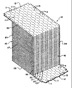
Figure 1 is an isometric view of a package of a folded web according
to the present invention with the web being divided into individual strip
elements at
longitudinally extending dividing lines, the package being shown prior to
completion of splices connecting one strip element to the next and with the
flexible
packaging material omitted for convenience of illustration.
Figure 2 is a top plan view of a package similar to the package of
Figure 1, with the flexible packaging material included and showing a modified
shape of the dividing lines.
Figure 3 is an isometric view of the package of Figure 1 showing a
reduced number of strip elements for convenience of illustration and showing
the
splice connections from each to the next.
Figure 4 is a side elevational view of an apparatus and method for
forming the package of Figure 1.
Figure 5 is a top plan view of the apparatus of Figure 4.
CA 02436221 2003-08-08
WO 02/076865 PCT/US02/08772
8
Figure 6 is a side elevational view on an enlarged scale of the
cutting roller for forming the dividing lines of the machine of Figure 4
showing the
bridge elements which join each strip element to the next.
Figure 7 is a top plan view of the cutting roller and a portion of the
web of Figure 14.
Figure 8 is a schematic side elevational view of a manufacturing line
for cuffing the strip info sheets.
Figure 9 is a top plan view of the line of Figure 8 where the strip
portions or sheets are cut from the strip at the narrowest part.
Figure 10 is a top plan view of a part only of Figure 8 where the strip
portions or sheets are cut from the strip at the widest part.
In the drawings, like characters of reference indicate corresponding
parts in the different figures.
DETAILED DESCRIPTION
As shown in Figures 1, 2 and 3, one embodiment of package
comprises a generally rectangular body or block 10 formed from a fan folded
web
12 divided into a plurality of side by side strips 11 at dividing lines 13.
The web is
formed of a material to be packaged. Generally, this material will be of a
fibrous
nature, formed by woven or non-woven material, although this is not essential
to
the package structure. Many materials of various thicknesses can be packaged
using the festooning technique, provided they can accept the creasing
necessary
at the end of each portion. The web is fan folded so that each web portion is
folded relative to one next adjacent folded web portion about a first fold
line
transverse to the web and relative to a second next adjacent folded web
portion
about a second fold line transverse to the web and spaced longitudinally of
the
web from the first fold line.
The package body is formed of the web 12 defining the plurality of
side by side stacks of the strip 11 where each stack comprises a plurality of
folded
strip portions of the strip which are laid on top of one another. Thus, as
shown in
Figure 3, the web 12 is folded back and forth at respective end fold lines 25
and
26 so that the fold lines lie in a common vertical plane defining the ends 15
and 16
CA 02436221 2003-08-08
WO 02/076865 PCT/US02/08772
9
of the stack. Each portion of the web lies directly on top of the previous
portion so
that side edges 27 and 28 of the portions of the web define a first set of
lines in a
common plane at right angles to the web portions which contain all the side
edges
27 of the stack, and, similarly, the side edges 28 of the web of the stack of
the
web define a second set of lines in the common plane at right angles to the
web
portions which contain all the side edges 28 of the stack.
Thus, the package is formed by stacking the portions each on top of
the next from a bottom end portion 29 up to a top end portion 30 to form the
stack.
The package is thus formed from the plurality of side by side stacks 20, 21,
22, 23
of the side by side strips divided from the web 12. Each of the stacks has a
Length
equal to that of the other stacks and therefore equal to that of the package.
The
stacks are formed up to a common height which is therefore equal to the height
of
the package.
The package 10 is thus formed from a plurality of individual stacks of
the strip arranged side by side. In Figure 1, there are shown eleven such
stacks,
whereas in Figure 3, for convenience of illustration, there are shown four
such
stacks arranged side by side forming a complete package structure defined by
the
folded web. Each stack is formed from a folded strip which is continuous
through
the stack. Each stack has a top end portion 30, a bottom end portion 29, two
ends 15 and 16 which are opposed, and two sides which are opposed.
It will of course be appreciated that the dimensions of the package
can be varied according to the requirements so that the number of stacks can
be
increased or decreased, the length and height of each stack can be varied to
increase the number of folded strip portions and to increase the length of the
folded strip portions.
As best shown in Figure 2 in the plan view of the strips, the strips of
each stack are folded back and forth from the fold lines 25 to the fold lines
26 to
form a folded strip portion having a length equal to the distance between the
fold
lines.
As described hereinafter, the strips are divided each from the next in
the web by the dividing lines 13 so that they have a varying width between the
side edges of the strip. In the example shown, the strips are of a simple form
in
CA 02436221 2003-08-08
WO 02/076865 PCT/US02/08772
which the width varies periodically between narrow sections 32 and wider
sections
33. More complex width variations can be employed in other examples. The
variation can be curvilinear as shown in Figure 2 or may include straight line
sections at the widest and narrowest parts as shown in Figures 1 and 3 with
5 inclined parts of the dividing lines in between the widest and narrowest
parts.
The dividing lines are each formed as described hereinafter by a
blade which presses against an anvil roller. The blade has continuous blade
elements separated by cut-outs. The blade elements act with the anvil roller
to
crush or cut the material and at the cut outs the material remains uncrushed
or
10 uncut or intact. Depending upon the type of material, the blades may
actually cut
the material or may crush the material while leaving it unbroken or un-slit,
thus
forming a line of weakness at which the material can readily tear. Thus, in
effect,
the blades form a series of tear lines in the web, each tear line lying along
the
respective dividing line and each longitudinally spaced from the next by a
bridge
portion of the dividing line at which the web is intact.
The dividing lines are arranged such that each strip element is
longitudinally continuous through the length of the folded web and such that
each
strip element can be unfolded in turn by pulling the strip element and
separating it
from a remaining part of the folded web by breaking the bridge portions.
In the example shown, the strip is intended for manufacturing
diapers or similar products which are formed each from a respective sheet
element cut from the length of the strip. Each sheet element in the example
shown has an intended cut line 34 at the wider section 33 and a second
intended
cut line 35 also at the wider section 33 so that the narrower section 32 is
located
between the intended cut lines.
It will be appreciated that in the package structure as shown, no
cutting of the strips in the transverse direction has yet occurred and the cut
lines
34 and 35 are, in effect, imaginary lines. Their position can however be
determined by the design of the sheet elements and the position along the
length
of the strip which forms the beginning and end of the sheet elements. The
sheet
elements are, in effect, thus arranged end to end so that each is separated
from
the next simply by cutting along the intended cut line.
CA 02436221 2003-08-08
WO 02/076865 PCT/US02/08772
11
It will be noted therefore from Figure 2 that each folded strip portion
of each of the package bodies is defined by an exact whole number of sheet
elements. In the example shown, the number of sheet elements is three, but
this
of course can be varied from a minimum of one up to a maximum which depends
solely upon the maximum allowable size of the transportable package structure.
In most cases, it is preferred that the folded strip portion will contain more
than
one sheet element since the sheet elements are often of the order of six
inches to
two feet in length and the required package structure will be generally
significantly
larger than this and certainly of the order of four feet in length.
In the example shown, the design of the wider and narrower portions
of the strip is arranged such that no waste is formed when the slitting action
occurs and the wider portions match.exactly with the narrower portions of the
next
strip. However, it is possible in some examples that there will not be an
exact
match between the wider portions of one strip and the narrower portions of the
next adjacent strip so that some waste pieces will be formed by cutting out of
the
structure and discarding of those waste pieces.
Thus, as shown in Figure 2, the strip portions will nest each exactly
along side the next, with the narrower portions of one receiving the wider
portions
of the next.
The fact that the folded strip portion contains a whole number of the
sheet elements and the sheet elements are identical ensures that the side
edges
of the each folded strip portion lie directly on top of the side edges of the
previously laid folded strip portions. This allows the individual stacks to be
unfolded in turn without any interleaving of the strip portions of one stack
within
the strip portions of the next adjacent stack which would prevent unfolding.
As
shown in the drawings, the strips throughout the height of the stack are
exactly
overlying. However, this requires an exact registration throughout the package
of
the length of the web portion as laid down between the fold lines with the
length of
the strip portions times the number of strip portions between the fold lines.
However, this exact registration may be difficult to achieve and any small
divergence will not interfere with the unfolding since that small divergence
will not
be enough to cause interleaving between adjacent strip elements. However, the
CA 02436221 2003-08-08
WO 02/076865 PCT/US02/08772
12
widest parts of the strip elements may not form an exact straight vertical
line but
may be inclined as the slight divergence in the length between fold lines from
the
theoretically required length gradually shifts the widest part along the strip
elements as laid down.
In the embodiment shown in Figures 1, 2 and 3 it will be noted that
the position of the fold lines relative to the sheet elements is of no
importance and
it is possible to accept a fold line 35A at a position along the length of the
sheet
element different from the intended cut line 35. Thus, the fold lines are
aligned but
the sheet elements are longitudinally offset.
The package is wrapped by a flexible packaging material, preferably
of heat sealable non-permeable plastics, which encompasses the whole of the
package as indicated at 40 (not shown in Figure 1). The packaging material
forms
a sealed package which allows air to be extracted from the package in a vacuum
action which can be used with physical compression D from the top and bottom
of
the package so as to compress the package to a reduced height in a vacuum
packaging system. The amount of compression can be determined so as to
minimize the volume of the package without interfering with the required loft
of the
product when withdrawn from the package. In this way, the package structure
avoids the necessity for rigid sides of a box or similar container so the
package
structure is stable due to the compression of the layers to reduce the height
of the
layers and due to the pressure of each layer against the sides of the next
adjacent
layers. In an alternative packaging system, physical compression is combined
with a heat shrink material in a bag which compresses and wraps the package.
Top and bottom headers can be used to prevent distortion of and damage to the
package.
Compression of the package is only practical in the direction D
which is at right angles to the surfaces of the portions of the strip. This
acts to
compress the height of the stacks so that the thickness of each strip portion
in the
direction D is reduced by that compression. Compression along the portions or
at
right angles to the stacks is not practical since this will act to distort the
strip.
Mechanical compression of the package in the direction D thus reduces the
dimension of the package in that direction allowing the air to be withdrawn
from
CA 02436221 2003-08-08
WO 02/076865 PCT/US02/08772
13
the flexible packaging material 40 causing the packaging material to be pulled
down onto the package to maintain it in its compressed condition and to apply
pressures tending to hold the stacks in intimate contact.
The strip of each stack is connected to fihe next by a traverse or
spliced portion of the strip which extends from one stack to the next so as to
form
a continuous strip through the full length of the package. The technique for
connecting the strip of each stack to the next layer is shown and described in
more detail in the above prior patent of O'Connor and is shown in Figure 3.
Thus,
four stacks 20, 21, 22 and 23 are shown. The strip of each stack is continuous
from the top end portion 30 to a bottom end portion 29. The connection is
effected by a tail portion 48 which extends from the bottom portion 47 beyond
one
end of the stack. The portion 48 extends along the end of the stack at 50 and
includes a twist 51 with fold lines 52 and 53 to form a portion 54 extending
along
the end of the next adjacent stack. The portion 54 is connected by a splice 55
to
the top portion 46 of the next adjacent stack.
Marking of the intended cut lines may be provided if required, as
shown at 57 applied by a marker 56. The markings can comprise an ink jet
marking, possibly in the form of a dot or square, visible both to the eye and
to the
machine or in some cases just to the machine. The marking may or may not be
located directly at the cut line depending upon the location of the machine
reader
relative to the cutting blade and in the example shown, the marking is located
in
advance of the intended cut line. The marking may extend only across a short
part of the width of the strip. It will be appreciated that as the markings
are
registered with respective ones of the cut lines, each marking is offset from
its
associated cut line by the same distance.
Turning now to Figures 8, 9 and 10, there is shown schematically
the unfolding and cutting line for using the strip and separating the strip
into the
separate sheet elements and assembly of those sheet elemenfis with other
components into a composite article such as a diaper or feminine hygiene
product. Thus, the package is indicated at 10 and the strip 11 is withdrawn
from
the package over a guide member 80 for directing into an operating line 81. A
CA 02436221 2003-08-08
WO 02/076865 PCT/US02/08772
14
cutting device 82 is operated by a control unit 83 which receives registration
information from a reader or sensor 84.
The reader of scanner 84 can be arranged to detect either the
markings 57 applied to the strip prior to unfolding or the width of the strip
or the
length of a strip portion so as to operate the cutter 82 at the required
location.
Thus, in a preferred embodiment, the reader 84 detects the locations of
maximum
width and effects a cutting action at the required location to separate the
strip into
the required pieces.
Yet further, the cutter 82 may be of a more complex arrangement so
that instead of simply cutting a transverse line the cutter acts to cut out a
portion
of the strip in a required shape as indicated schematically at 85 in Figure 9
and
85A in Figure 10. The variable width strip allows a variable width portion to
be cut
out while minimizing the waste on either side of the cut out portion 85, 85A.
The
ends of the cut out portion indicated at 86 and 87 in Figure 9 can be located
at the
narrowest part of the strip as shown in Figure 9 or at the widest part as
shown in
Figure 10. The transverse dividing line between the two sheet elements and, in
some cases, the cut out fines 86 and 87, may be curved so as to provide a
curvature to the outer periphery of the cut out portion 85 which is bowed
outwardly
in Figure 9 and bowed inwardly in Figure 10.
Thus the withdrawn strip element is cut at longitudinally spaced
positions into a series of identical strip portions each of which is assembled
with
other components into a respective one of the composite articles. The strip
elements are shaped cyclically by the dividing lines to define a series of
cycles
formed by a strip part of greatest width followed by a strip part of least
width and
wherein each identical strip portion includes a single cycle. In Figure 10,
each
identical strip portion is cut from the next at the part of greatest width. In
Figure 9,
each identical strip portion is cut from the next at the part of least width.
Downstream of the cutter 82, the cut sheet piece is fed into an
assembly system indicated at 88 where the cut piece is assembled with other
components to feed the finished products into a finished product line 89.
These
arrangements are shown only schematically since the construction of a diaper
assembly line is well known to one skilled in the art. Thus it will be
appreciated
CA 02436221 2003-08-08
WO 02/076865 PCT/US02/08772
that the cut sheet piece is one portion only of a finished composite article
where
the composite article is formed in individual separated pieces for sale and
use
independently. The cutter 82 may form part of the assembly line 88.
A package folding apparatus 59, shown in Figures 4, 5, 6 and 7,
5 includes a supply roll 59A. The apparatus passes the web from the supply
roll
through nip rolls 59B and 59C and over a guide roller 58. The apparatus
includes
a slitting roller 60 which, instead of forming a continuous longitudinal slit
line,
forms lines which are formed partially by slits leaving periodic bridge
portions 61.
Thus, as shown in Figure 6, the roller 60 has a peripheral blade portion 63
with
10 cutouts 64 arranged at angularly spaced positions around the peripheral
blade 63.
Thus, when the cutting blade 63 acts in cooperation with the anvil roller 62,
it
forms slits 65 separated by bridge portions 61 where no slitting action has
occurred.
In practice, the cutouts 64 may have a width of the order of 0.2 mm.
15 The number of cuff outs around the periphery of the cutting roller may vary
widely
from only one in a circumference of 10 inches up to as many as 20 in a
circumference of 10 inches. The number depends upon the material in that the
number is reduced where the material has sufficient strength that a reduced
number of bridges provides the necessary interconnection between the strip
elements to hold those strip elements together during further processing.
As shown in Figure 7, the blade 63 is shaped to define the diverging
portions 66 and 67 either side of an imaginary center line 68 so as to provide
the
wider and narrower sections of the strip elements. In the arrangement shown in
Figure 7, the wider and narrower diverging sections are shown using straight
lines
as opposed to the curvi-linear arrangement of Figure 2. The shape of the
divergence from the center line 68 will vary depending upon requirements so
that
the shape of the finished strip element is tailored to the shape of the end
use
sheet as required while minimizing the amount of waste material carried by the
strip element. The amount of divergence from the center line can also vary
significantly depending upon the end use.
In the embodiment shown in Figure 4, the folding system 59
comprises a pair of drums 591 and 592 which carry mechanical grippers 593 at
CA 02436221 2003-08-08
WO 02/076865 PCT/US02/08772
16
angularly spaced positions around the drums. The drums have their axes
generally parallel to the fold lines. The mechanical grippers 593 are shown
only
schematically but act to grasp the material of the web at the position of
closest
approach of the drums centrally between the fold lines of the package
structure.
The mechanical grippers alternately grasp the web fed from the roller 58 and
carry
that web around that one of the rollers to which the web is attached as
indicated at
594 thus carrying the web to form the fold line 595. After that fold line is
formed,
the web is grasped by the other of the rollers and carried to the stack of
fold lines
as indicated at 596.
The fact that the strip elements are still connected by the bridge
portions ensures that the web as a whole folds as a web rather than as
individual
strip elements, thus allowing the web to be grasped more easily and maintained
without creases and without overlapping or interleaving of the individual
strip
elements. The drums are arranged to carry the web around approximately
120°
from the point of closest approach to the discard position at the fold lines
595,
596.
As shown in Figures 2 and 5, the cutting roller 60 forms a series of
the dividing lines 69 at spaced positions across the web. The divergence from
the
center line 568 is arranged so that adjacent pairs of dividing lines 69 are in
opposite phase so as to form nested wider and narrower portions of the strip
elements as previously described. At the edges of the web, as indicated at 90
and 91, the adjacent dividing line 69 forms an edge strip portion 92, 93,
respectively, which is defined by the side edge 90, 91, respectively, on one
side
and by the adjacent dividing line 69 on the other side. The strip portions 92
and
93 can be minimized in width but are preferably sufficiently wide so that the
dividing line does not intersect the side edge 90, 91 thus forming the edge
strip
portion as a continuous strip of varying width. Alternatively, the edge strip
portions
comprise a full width of a strip plus an edge portion with one straight side
edge so
that the edge strip portion is used as a continuation of the other strips but
a little
wider so that more is cut out from the edge strip portion at the die cutter
82.
In the arrangement as shown, the edge strip portions 92 and 93 are
left in place when the packaging material is applied to wrap the structure.
The
CA 02436221 2003-08-08
WO 02/076865 PCT/US02/08772
17
portions 92 and 93 thus define for the sides of the block of the folded web
planar
side surfaces defined by the edge 90, 91 of the web. This ensures that the
edges
of the first strip element adjacent the side edges are protected by those
strip
portions 92 and 93 and the compression by the packaging does not damage the
wider parts of the strip elements by impact or compression.
The packaging material can be applied as a vacuum formed bag or
as a heat shrink wrapping material. Other packaging materials may also be
used,
particularly bearing in mind that the structure is a rectangular block defined
by the
planar sides 90 and 91 and by the planar ends containing the fold lines 595,
596.
At the unwinding station shown in Figures 8 and 9, the block 10 is
unwound so that each strip element is unfolded and supplied to the machine as
previously described. Prior to the first strip element being fed from one side
of the
block, the adjacent side strip portion 92, 93 is pulled away. This can be
effected
manually as a slab or block simply by pulling the whole structure containing
the
folded strip portion down away from the adjacent strip element. Alternatively,
the
waste strip portion 92, 93, can be stripped away from the adjacent strip
element
as it is fed and discharged into a suction removal device.
In some arrangements where the amount of width variation is
relatively small, the end strip portions 92 and 93 can be removed prior to
folding in
a vacuum trim remover or subsequent to folding by manually pulling away.
It will be noted in the arrangements of Figure 2 that the fold lines of
the individual strip elements are arranged to occur at the center line and at
the
end of one portion of the strip element so that the structure is symmetrical
and the
wider portions of the strip elements directly overlie the wider portions of
the
underlying strip elements in the folding action. Thus, the side edges of the
.strip
elements along their full length are directly overlying in the folded
condition. This
avoids any edge portions of the strip elements from being trapped between the
folded portions of the strip element next adjacent.
While the arrangements described above show a packaging
system for the strip elements which acts to fold those strip elements in a
manner
which allows nesting of one folded stack relative to the next, alternative
packaging
systems may be developed for the strips of varying width. Thus, the present
CA 02436221 2003-08-08
WO 02/076865 PCT/US02/08772
18
invention is not limited to the particular packaging methods set forth in the
above
description and shown in the drawings. For example, such strips may be
packaged using conventional festoon boxes, or may be packaged using other
conventional techniques.
Since various modifications can be made in my invention as herein
above described, and many apparently widely different embodiments of same
made within the spirit and scope of the claims without departing from such
spirit
and scope, it is intended that all matter contained in the accompanying
specification shall be interpreted as illustrative only and not in a limiting
sense.