Note: Descriptions are shown in the official language in which they were submitted.
CA 02436543 2003-07-29
WO 02/060516 PCT/GB02/00329
1
Method and apparatus for filling needleless injector capsules
Needleless injectors are devices for delivery liquid drugs through the
epidermis
of a patient without using a conventional hypodermic needle. The normal
principle of
operation is to dispense a fine jet of liquid from a drug capsule at
sufficiently high
pressure and velocity to pierce the skin and deposit within the underlying
tissues. The
better designs of injectors usually have a two-phase injection pressure
profile: the first
is a very fast rise time from zero to a high pressure - typically in the
region of 300 bars
- which is the skin-piercing phase, followed by the remaining injectate at a
lower
pressure, which is sufficient to keep the hoke in the skin open during the
injection. The
high pressure is usually developed by a gas spring or pneumatic ram, or
sometimes by
pyrotechnic means.
Typically, the drug capsule is a cylinder with one end open, and the other
having the injection orifice. A piston is located within the bore, and the
drug is
contained between the orifice and piston, the orifice being sealed temporarily
by a
rubber plug, cap or other known means.
Drug capsules are often made from a transparent thermoplastic, but at high
strain rate these materials are brittle, and a problem that can occur during
the high
pressure phase is that the drug capsule can burst. It is possible to make the
wall of the
drug capsule sufficiently thick to withstand the burst pressure, but this may
result in an
unacceptably large device which is more difficult to make, and more expensive.
This
problem is exacerbated by the presence of bubbles of air trapped within the
capsule
after filling. This is thought to be because of shock waves produced by the
rapid
collapse and expansion of the bubbles during the transition from the first and
second
pressure phases. The size of the bubble has an influence - those below about 2
microlitres volume having an insignificant effect. Larger bubbles, apart from
the
aforementioned problem, also compromise the accuracy of filling, so that an
incorrect
dose might be delivered. Another problem with some drugs, such as adrenaline,
is that
they are sensitive to the presence of oxygen, and it is necessary to reduce
the volume
of trapped air to a minimum.
Increasingly, it is preferred that the capsules are pre-filled by the
manufacturers
on specialized filling machines: this ensures good quality control, sterility,
and
CA 02436543 2007-01-25
2
traceability, and it follows from the foregoing that the volume of air trapped
in the
injectate should be as small as possible. Equally, low cost production demands
high
filling rates, typically less than 1 second for lml fill volume. Current
filling machines
for both syringes and needleless injector capsules employ vacuum to reduce the
amount
of air trapped, but the vacuum systems operate at around 15 to 20 mbar or
higher,
which means that a significant amount of air remains in the syringe or capsule
before
the liquid drug in introduced. It is possible to design a vacuum system which
can
operate at lower pressure, but these require very large reservoirs, and
consequently
extended pump-down times and long filling cycles. It would be possible to
avoid the
use of reservoirs and to connect the capsule to be evacuated directly to a
vacuum pump,
but the fmal pressure, pumping times, and overall control, would be highly
unsatisfactory except in the most crude applications.
The present invention is for a two-stage vacuum system which will rapidly
evacuate needleless injector drug capsules, syringes and the like to low
pressure prior
to filling, without requiring cumbersome and inconveniently large reservoirs.
In an
advance over the prior art, there are provided reservoirs which may be
connected
sequentially to the capsule to be filled, so that the pressure within the
capsule is
lowered by pre-determined steps, in a highly repeatable manner, before
filling.
According to the present invention there is provided a method of filling a
needleless injector capsule with a material to be dispensed therefrom, which
comprises
connecting the capsule successively to at least a first reservoir at a sub-
atmospheric
pressure and a second reservoir at a sub-atmospheric pressure, and thereafter
introducing the said material into the capsule.
CA 02436543 2007-01-25
2a
According to the present invention, there is also provided a method of filling
a
needleless injector capsule, comprising the steps of:
(a) connecting a needleless injector capsule to a first reservoir at a first
sub-atmospheric
pressure and thereby reducing an interior volume of the capsule to the first
sub-atmospheric
pressure;
(b) connecting the capsule to a second reservoir at a second sub-atmospheric
pressure
which is below the first sub-atmospheric pressure and thereby reducing the
interior volume
of the capsule to the second sub-atmospheric pressure; and
(c) introducing a liquid drug into the capsule.
According to the present invention, there is also provided An apparatus for
filling a
needleless injector capsule with a material to be dispensed therefrom, which
comprises a
first reservoir; a second reservoir, suction means for reducing the pressure
in each reservoir
to a respective sub-atmospheric pressure; a connection arrangement for
connecting the
capsule successively to the first and second reservoirs; and a filling device
for thereafter
introducing the said material into the capsule.
In a preferred embodiment, there is provided a filling head which seals
against the
orifice of a drug capsule which has a piston or plunger already assembled
therein, or
otherwise has the open end sealed against the ingress of atmospheric air.
Connected to the
filling head is a vacuum system which first connects the capsule to a vacuum
reservoir
evacuated in 1 mbar; this raises the pressure of the capsule and reservoir to
15 mbar. This
increased pressure within the combined reservoir and capsule would be too high
to ensure
minimal volume of trapped air within a filled capsule, and a second process
stage isolates
the first reservoir and connects the capsule to a second reservoir evacuated
to 0.1 mbar.
Since the capsule is already at a reduced pressure of
CA 02436543 2003-07-29
WO 02/060516 PCT/GB02/00329
3
15 mbar, the resulting pressure in the order of 1 mbar is reached very
quickly, and the
capsule may be filled. A third process stage is to isolate both vacuum
reservoirs and
open the filling head to atmosphere to allow the capsule to be removed.
The volume of each reservoir is pre-determined in a fixed ratio to the volume
of the capsule, connection pipes, valves and other ancillary equipment. One or
more
additional reservoir may be used and connected sequentially, and the pressures
mentioned above are for illustration purposes only and may vary according to
the
application.
The presently preferred embodiment will now be described with reference to the
accompanying drawings, in which:
Figures 1, 2 and 3 show the evacuation sequence for a ten-head filler,
(although
the present invention is applicable to filling machines with any number of
heads); and
Figures 4a, 4b and 4c are centre-line cross sections through a suitable type
of
filling head an drug capsule of cylindrical form, to show the sequence of
evacuation,
sealing and filling.
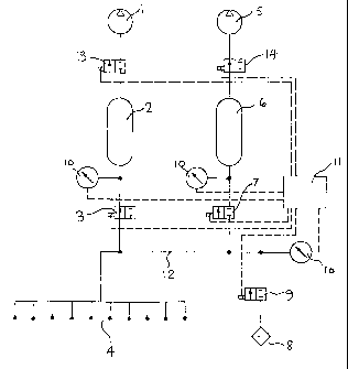
Referring to Figure 1, the inlet of vacuum pump 1 is connected via an
isolation
valve 13 to reservoir 2, and the inlet of reservoir 2 is connected to a 2-port
valve 3.
Similarly, vacuum pump 5 is connected via isolation valve 14 to reservoir 5,
the inlet
of which is connected to the 2-port valve 7. The inlets of valves 3 and 7 are
connected
to the common vacuum bus 12. Connected to the vacuum bus 12 are the filling
heads
4, and an air admittance valve 9. Transmitting gauges 10 are connected to the
pipework to provide indications of the pressures during the filling cycle, and
to transmit
control signals to a sequence controller 11.
Referring now to Figure 4a, a capsule 40 is located with an interference fit
within a sleeve 41. Sleeve 41 =has a tubular extension 42, frangibly connected
at 43,
and the extension 42 has a resilient interface seal 47 fixed so that it forms
a vacuum
and liquid-tight seal on the face 49 of the capsule 40 and the inner surface
of the
extension 42. The seal 47 is perforated by a conduit 48 which is in hydraulic
and
vacuum connection with the injection orifice 44 of capsule 40. Sealingly and
slidingly
located within the bore of capsule 40 is a piston 45; its location is such
that the volume
46 between the orifice and the piston is that which is required to be filled
with liquid
drug. A filling head 60 is shown sealingly engaged with the extension 42. The
filling
CA 02436543 2003-07-29
WO 02/060516 PCT/GB02/00329
4
head 60 has a resilient seal 61 which makes a vacuum-tight seal between the
head 60
and the rim 50 of the extension 42. A filling tube 63 is located for
longitudinal sliding
movement within a vacuum-right tube seal 64. The filling tube 63 is provided
with a
connection 65 for liquid input, and the filling head 60 is provided with a
connection 62
for vacuum. A tip sealing valve 66 is shown sealing the outlet orifice 67 of
the filling
tube 64. Figure 4a thus shows the position of the capsule and filling head
components
in a ready-to-evacuate state.
Referring to Figure 4b, this shows the filling tube 63 located sealingly on
the
interface seal 47, so that the outlet orifice 67 is in vacuum and liquid-tight
connection
with the conduit 48. This is the position after evacuation of the capsule 40,
and
immediately prior to filling with liquid.
Figure 4c is similar to Figure 4b, except that the tip sealing valve 66 is
lifted
to open the outlet orifice 67. This permits liquid to flow from a liquid
supply source
(not shown) through connection 65, through the bore of filling tube 63, the
outlet
orifice 67, the conduit 48 and into the volume 46.
The filling sequence will now be described, starting by reference to Figure 3.
The approximate pressures achieved are for illustration only, and a calculated
example
will follow.
Stage 1
Figure 3 shows diagrammatically ten filling heads and capsules 4 (which are as
shown in Figures 4a, 4b and 4c) connected in parallel to the vacuum bus. Valve
9 is
open, and thus connects the filling heads 4, via bus 12, to the atmosphere via
filter 8.
During this stage, valves 3 and 7 are closed, and the vacuum reservoirs 2 and
6 are
being evacuated by pumps 1 and 5 respectively until the required vacuum is
reached,
when the valves 13 and 14 close to isolate the reservoirs 1 and 5. Reservoir 2
is
evacuated to a pressure of 1 mbar, and reservoir 6 is evacuated to a pressure
of 0.1
mbar by vacuum pump 5. Now, referring to Figure 1, valve 9 is then closed, and
valve 3 is opened, thus connecting the filling heads 4 to the reservoir 2 via
bus 12.
The filling heads and capsules are as shown in Figure 4a. Note that the tip
sealing
valve 66 is closed to prevent the vacuum drawing out any liquid during the
evacuation
stage of the cycle.
CA 02436543 2003-07-29
WO 02/060516 PCT/GB02/00329
Stage 2
Referring to Figure 1, valves 9, 13, 14 and 7 are closed, and valve 3 is open,
thus connecting the reservoir 2 to the filling heads 4 via bus 12. The
atmospheric air
which was contained in the bus 12 and filling heads 4 is therefore expanded to
a lower
pressure, dependent upon the ratio of the volume of reservoir 2 and the volume
of the
bus 12, filling heads 4 and any ancillary equipment such as the gauges 10, say
15 mbar.
Stage 3
This stage reduces the pressure in the filling heads 4 as follows. Referring
to
Figure 2, valve 3 is closed, after which valve 7 is opened, and this connects
the filling
heads 4 to the vacuum reservoir 6 via bus 12. Since the filling heads 4 and
bus 12 are
already at a reduced pressure of about 15 mbar from stage 2, there is a
further
reduction in pressure to about 1 mbar as the small amount of air in the system
expands
to fill reservoir 6. This expansion is very rapid - much less than one second
for typical
small volume containers. During this stage, the valve 13 may be open to
evacuate the
reservoir 2 ready for the next cycle.
When the pressure in the filling heads 4 is sufficiently low, referring to
Figure
4b, the capsule volume 46 and extension volume 51 are at a pressure of 1 mbar,
and
the outlet orifice 67 of filling tube 63 is now brought into sealing
connection with the
conduit 48 in the resilient interface seal 47. Liquid connection 65 is
connected to a
source of the liquid 52 (not shown) to be transferred to the capsule 40. The
liquid 52
may be at above atmospheric pressure to overcome the resistance to flow of the
filling
tube 67 and associated pipework. As shown in Figure 4c, the tip sealing valve
66 is
now opened, and the liquid 52 thus flows into the volume 46. The pressure in
the
volume 46 was 1 mbar, so it follows that the maximum volume of air that could
be
trapped within the volume 46 is one thousandth of the said volume.
Stage 4
Following stage 3, the valve 7 may be closed to allow the reservoir 6 to be
evacuated to the required level. With both valves 3 and 7 now closed, valve 9
is
opened to connect the bus 12 and filling heads 4 to atmosphere - i.e. to
release the
vacuum. It is preferred in pharmaceutical filling operations to prevent
airborne bacteria
CA 02436543 2003-07-29
WO 02/060516 PCT/GB02/00329
6
and other contaminants from reaching the various parts of the bus, valves and
reservoirs, and the atmospheric air may be taken in via the filter 8.
Referring to Figure
4a, this is the position of each filling head 60 at the end of the e'vacuation
and filling
cycle. The head 60 is then removed from the extension 42 of capsule sleeve 41,
and
a sealing stopper or similar device is inserted into the bore of the extension
42 to seal
against the ingress of dirt and bacteria, and to prevent loss of liquid by
evaporation.
Alternatively, a sealing pin may be inserted in the conduit 48. The filled
capsule is
removed, and the filling and sealing cycle is complete.
Transmitting gauges 10 inform the controller 11 that the correct conditions
exist
for each part of the sequence to begin. A number of safety devices such as
pressure
switches would be used in practical installations, but have been omitted from
the
description in the interests of clarity. Also, in a multiple filling head
embodiment, it
may be necessary to incorporate isolation valves to each head to prevent a
malfunction
in a filling head causing a massive air leak.
To avoid bubbles being formed in the liquid after filling according to the
present
invention, it may be necessary for the liquid to be de-gassed before filling.
As discussed, one of the objectives of the invention is to achieve predictable
and
repeatable pressures within the capsule prior to filling, and it may be seen
from the
foregoing that by sequentially connecting the capsules to fixed volume
reservoirs at
known pressures, this objective may be achieved. As an illustration, the
following is
a calculated example of a typical installation, using the Figures 1 to 3 and
4a to 4c as
references.
Pressures throughout are calculated using the ideal gas law equation:
PV = m/M R.T = v.R.T (1)
NB v may be replaced by n
Where P = pressure exerted by gas (N/m2)
V = volume of gas (m3)
n number of moles present in volume V
R = gas constant (kJ/kmole.K) or (kNm/kmole.k)
= 8.3144 kJ/kmole.K
T temperature of gas K
Calculations involving vacuum usually quote pressures in mbar and volumes in
CA 02436543 2003-07-29
WO 02/060516 PCT/GB02/00329
7
litres, hence:
R becomes 83.14 mbar .1 . mole 1. K-'
Now with reference to Figure 1,
Let PI = pressure in reservoir 2
V, = volume of reservoir 2
nl = number of moles of air in reservoir 2
Tl = temperature of reservoir 1
P2 = pressure in reservoir 6
V2 = volume of reservoir 6
n2 = number of moles of air in reservoir 6
P3 = pressure in vacuum bus
V3 = volume of vacuum bus
(note that V3 = volume of pipes, gauges, valves and fittings)
Calculation of vacuum bus volume V,
Let volume of vacuum line connecting filler head + dead space in filler head
= 2ml thus for 10 filling heads, volume is 2 x 10 =20ml = 0.02 litres
Let volume 46 of capsule 40 and volume 51 of extension 42 = lml, thus for 10
capsules is 1 x 10 = lOml = 0.01 litres
Let the inside diameter of each filling head connecting tube be 500mm, and the
inside diameter be 3mm. Thus the volume of 1 line is 3534 mm3 and 101ines is
10 x
3534 = 35340 mm3 = 0.0353 litres
Let the volume of the vacuum bus be 0.0035 litres
Total volume V3 = 0.0688 litres
Then for stage 1:
[1] number of moles in reservoir 2, nl
Let P, = 1 x 10⁻¹ mbar V, = 5 litres T, = 293 K
P1V1 = n1RT, .'. nl = 1 x 10-1.5 = 2.05 x 10⁻⁵ moles air
83.14 x 293
CA 02436543 2003-07-29
WO 02/060516 PCT/GB02/00329
8
[2] number of moles in vacuum system (or bus), V3
Let P3 = 1000 mbar V3 = 0.07 litres
.'. n3 = 1000 x 0.07 = 0.00287 moles air
83.14 x 293
[3] On release of valve 3, total volume V3 of the system is Vl + V3 and
therefore
the total number of moles is n5 = n, =n3
Thus the system pressure P5 after 15` stage vacuum is n5RT5
V5
_(2.05 x 10'5 + 0.00287) x 83.14 x 293 mbar
(5 + 0.07)
.'. pressure in the system after 1s` stage evacuation is,13.9 mbar
Vacuum stage 2
[4] Number of moles in reservoir 6: as V,=Vz and Pi=P2,
n2 = n 2.05 x 10'S moles air
[5] Number of moles n3 remaining in vacuum system V5 after 2 d stage:
now the pressure in the line 'P3 = P5 = 13.9 mbar,
and the volume V3 = 0/07 litres
.'. n3 = P-Y-3 = 13.9 x 0.07 moles air
RT3 83.14 x 293
= 4 x 10⁻⁵ moles air
[6] Number of moles in system, n5:
n2 + n3 = 2.05 x 10-5 x 4 x 10-5 = 6.05 x 10-5 = 6.05 x 10⁻⁵ moles air
Thus the final pressure PS2 after the 2 a stage evacuation (i.e. immediately
before filling
the capsule with liquid), is
n,RT5 = 6.05 x 10-5 x 83.14 x 293
VS 5
= 0.29 mbar
CA 02436543 2003-07-29
WO 02/060516 PCT/GB02/00329
9
This is sufficiently low pressure to ensure that bubbles of air trapped within
the
liquid are insignificant. Note also that the calculations assume a perfect
system with
no leaks and outgassing; in practice very small leaks could occur, but the
example
given would be suitable for filling a 0.5ml capsule with a maximum bubble size
of
about 0.5 l.