Note: Descriptions are shown in the official language in which they were submitted.
CA 02436577 2008-05-27
- 1 -
BEARING DEVICE FOR THE ROTOR OF A ROTATING MACHINE
FIELD OF THE INVENTION
The present invention relates to the field of rotating
machines and particularly to a bearing arrangement for the
rotor of a rotating machine.
DISCUSSION OF BACKGROUND
In rotating machines of large dimensions, such as
vertically arranged hydrogenerators for example, special
problems occur when mounting the rotors in bearings, these
problems being caused in particular by the extreme ratio
between the external dimensions, which usually amount to
several meters, and the bearing play, which is within the
range of tenths of a mm. The rotors of such hydrogenerators
are normally fixed with regard to an axis of rotation by means
of two radial or guide bearings at a distance from one
another. The weight and other axial forces, originating in
particular from the water turbine, are absorbed by at least
one axial or supporting bearing, which is usually combined
with one of the radial bearings to form a combined axial and
radial bearing and is accommodated in a common bearing body.
The bearing bodies are the central bodies of a star-shaped
bearing bracket or star-shaped supporting bracket or star-
shaped guide bracket which is formed by supporting arms
starting from the bearing body in the radial direction. The
supporting arms, for absorbing axial forces, are supported
with their free outer ends in the axial direction either on
the foundation, which is normally
CA 02436577 2003-07-28
- 2 -
made of concrete and concentrically surrounds the
generator, or on the stator of the generator. Examples
of such star-shaped supporting brackets or star-shaped
guide brackets are described in CH-A5-578 708 mentioried
at the beginning or in US-A-4,258,280 corresponding
thereto or in CH-A5-583 469. An example of a combined
axial and radial bearing or supporting and guide
bearing is found in figure 1 of EP-Al-0 586 861.
In order to also be able to absorb radial forces which
are caused, for exarnple, by unbalance in the rotor or
by interactions between rotor and stator, the
supporting arms in the prior art have been extended in
the radial direction up to the surrounding concrete
wall and firmly screwed to metal elements embedded
there. As a result, high rigidity of the star-shaped
supporting bracket was achieved, this rigidity having
been determined essentially by the rigidity of the arms
stressed in compression in the longitudinal direction.
A disadvantage with this arrangement, however, is that
very high compressive forces acting in the radial
direction are produced during a thermal expansion of
the arms of the star-shaped supporting bracket, and
these compressive forces, especially in the case of
star-shaped supporting brackets arranged above the
machine, cannot be readily absorbed by the concrete
wall, which is rather thin there. In addition, such a
rigid construction introduces large radial forces into
the bearing housing. Said radial forces may affect the
bearing play due to resulting eccentricity or
deformation of the bearing housing and thus put the
operability of the bearing at risk in the extreme case.
It has therefore been proposed in CH-A5-583 469 already
mentioned to mutually stiffen the arms of a star-shaped
supporting bracket and to secure their free ends in the
tangential direction in the concrete wall by
prestressed rolling bodies, while they are mounted such
as to be displaceable in the radial direction.
CA 02436577 2003-07-28
- 3 -
On the other hand, CH-A5-578 708 mentioned at the
beginning has adopted another method of solving the
problem associated with the thermal expansion in the
case of star-shaped supporting brackets or star-shaped
guide brackets: used here for absorbing radial forces
are connecting elements which are arranged tangentially
to an imaginary cylinder coaxial to the axis of
rotation and - in a pure radial or guide bearing - form
the arms of the star-shaped bearing bracket (see fig. 2
of CH-A5-578 708) or - in a combined axial and radi.al
bearing - run betweerl the ends of the (radial)
supporting arms and the concrete wall (shown in fig. 6
of CH-A5-578 708) . In more recent hydroaenerators (as
are used, for example, in the Bieudron hydroelectric
plant, Switzerland; in this respect also see the
applicant's brochure "Hydro-generators with oblique
elements. Top technology from ALSTOM power", September
2000), the supporting arms of the combined supporting
and guide beari_ngs including the connecting elements
have a tangential orientation relative to the concrete
wall in a coritinuous robust welded construction.
The tangentially oriented arrangement of the connecting
elements or supporting arms achieves the effect that
thermal expansions are converted into uncritical
rotations of the bearing body about the machine axis.
The mode of operation of the tangentially oriented
connecting elements or oblique spokes is described in
detail in the publication Brown Boveri Mitteilungen 2,
volume 67, pages 108-116, February 1980.
However, a disadvantage with the conventional star-
shaped supporting brackets having tangentially oriented
connecting elemerlts is the direct linkage between the
actual supporting arms, which absorb the axial forces
and pass thein into the foundation, and the tangential
connecting elements, which corlvert the radial forces
CA 02436577 2003-07-28
- 4 -
into a rotation and are responsible for the centering
of the bearing body. This direct linkage leads on the
one hand to heavy constructions of the star-shaped
bearing bracket, which require a lot of material, and
prevents on the other hand separate optimization of the
construction elements responsible for the axial and
radial forces. In addition, asymmetrical deformations,
as may occur due to changes in the foundation or due to
powerful electromagnetic fields, cannot be readily
compensated for.
SUMMARY OF THE INVENTION
The object of the invention is therefore to provide a
bearing arrangement for the rotor of a rotati.ng
machine, in particular of a hydrogenerator rotating
about a vertical axis, which bearing arrangement avoids
the disadvantages of known bearing arrangements and is
distinguished in particular by a material-saving
construction, optimization of the individual bearing
functions and improved adjustability.
The object is achieved by all the features of claim 1
in their entirety. The essence of the invention, in the
combined axial and radial bearing, consists in
completely separating the absorption of the axial
forces, such as forces due to weight and thrust forces,
from the absorption of radial forces and from the
centering and radial guidance task by tangentially
oriented connecting elements being provided for the
absorption of radial forces and for the centering,
which connecting elements are linked with one end to
the foundation and with the other end directly to the
bearing body. The expression "tangential orientation"
within the scope of the present invention refers to the
fact that the connecting elements are arranged such as
to be inclined by an angle at their articulation point
in the circumferential direction relative to the
CA 02436577 2003-07-28
-
radius. This angle of inclination is at all events
greater than 00, preferably greater than 300, and
reaches 900 in the case of a fully tangential
orientation. This configuration can be regarded in a
5 simplified manner as a combination of two star-shaped
bearing brackets which are independent of one another.
As a result, it is possible, in particular, to dispense
with complicated transverse struts between the
supporting arms of the star-shaped bearing bracket. In
addition, the supporting construction can be simplified
and material and weight can thus be saved by the
arrangement according to the invention.
It is advantageous in this construction if the elements
which bear the axial load are designed to be flexible
in the circumferential direction and if the
tangentially oriented elements have as low a rigidity
as possible in the axial direction.
The tangentially oriented connecting elements are
preferably designed such as to be adjustable in their
length, the connecting elements being designed, in
particular, such as to be infinitely adjustable in
length like a turnbuckle by a combination of a left-
hand and a right-hand thread. As a result, it is
possible in a simple manner and at any time to carry
out centering or correct the centering and also
advantageously influence the operating behavior of the
rotor and of the entire machine by producing certain,
even nonuniformly distributed, prestresses.
The separation of the axially and radially acting star-
shaped bearing brackets and the flexible adaptation of
the bearing arrangement are further improved if the
connecting elements are also designed, as articulated
struts which are pivotably linked by means of bearing
blocks to the bearing bodv and to the foundation,
respectively. Such articulated struts and the
CA 02436577 2008-05-27
- 6 -
associated bearing blocks are obtainable as prefabricated
parts in different dimensions and thus reduce the costs of the
construction.
It is especially advantageous for the separation of the
axial and radial bearing functions if, within the combined
axial and radial bearing, the radial bearing and the axial
bearing are arranged offset from one another in the axial
direction, and the connecting elements are linked to the
bearing body in the region of the radial bearing and the
supporting arms are linked to the bearing body in the region
of the axial bearing.
According to a broad aspect of the present invention
there is provided a bearing arrangement for the rotor of a
rotating machine having a vertical axis. The arrangement
comprises a foundation circumferentially surrounding the
rotor. A bearing body is also provided and a combined axial
and radial bearing is positioned in the bearing body.
Supporting arms are fastened to the bearing body and
configured and arranged to bear axial forces, the supporting
arms each including a free end to be supported on a load-
bearing base. Tangentially oriented connecting elements are
positioned between the bearing body and the foundation. The
connecting elements are configured and arranged to bear radial
forces and center the bearing body. The connecting elements
are linked at a first end to the foundation and are fastened
at a second end to a coupling point arranged directly on the
bearing body.
BRIEF EXPLANATION OF THE FIGURES
The invention is to be explained in more detail below
with reference to exemplary embodiments in connection with the
drawing, in which:
CA 02436577 2008-05-27
- 6a -
FIG. 1 shows a schematic longitudinal section of the
rotor of a vertical hydrogenerator, this rotor being mounted
by means of a radial bearing and a combined axial and radial
bearing, as is especially suitable for the application of the
invention;
FIG. 2 shows a perspective view, obliquely from above,
of a preferred exemplary embodiment for a bearing arrangement
according to the invention in a hydrogenerator arranged in an
annular foundation according to the configuration shown in
FIG. 1; and
CA 02436577 2003-07-28
- 7 -
Fig. 3 shows a perspective oblique view, from below, of
the bearing arrangement from fig. 2 without the
foundation.
WAYS OF IMPLEMENTING THE INVENTION
A schematic longitudinal section of the rotor 11 of a
hydrogenerator 10 is shown in fig. 1, in which rotor 11
the invention can be used in an especially advantageous
manner. The invention shown may of course also be
advantageously used for other machines, such as, for
example, when mounting the propulsion line of large
ships in bearings. The rotor 11 rotates about a
vertical axis 19. It has a shaft 12 which is rotatably
mounted by means of a (bottom) radial bearing 16 and a
(top) combined axial and radial bearing 18. The
combined axial and radial bearing 18 comprises a second
radial bearing 15 and an axial bearing 14 arranged one
above the other, the shaft 12 resting on the axial
bearing 14 by means of a supporting ring 13. The radial
bearings 15, 16 are provided for guiding and centering
the rotor 11 with regard to the axis 19 of rotation. In
addition, they absorb radial forces, which may be
produced, for example, by unbalance of the rotor. The
axial bearing 14 absorbs the axial forces, which in
particular result from the dead weight of the rotor 11,
from the electromagnetic interaction between the rotor
11 and the stator (not shown in fig. 1) concentrically
surrounding it, and from the thrust which is produced
by the effect of the water on the turbine 17 attached
to the bottom end of the rotor 11. However, the
combined axial and radial bearing 18 may also change
position with the radial bearing 16 and may accordingly
be arranged at the bottom.
The present irivention, then, relates to the way in
which the axial and radial forces acting on the
combined axial and radial bearing 18 are passed
CA 02436577 2003-07-28
- 8 -
directly or via the stator into the foundation,
normally made of concrete, of the machine. To this end,
a preferred exemplary embodiment for a bearing
arrangement according to the invention is reproduced in
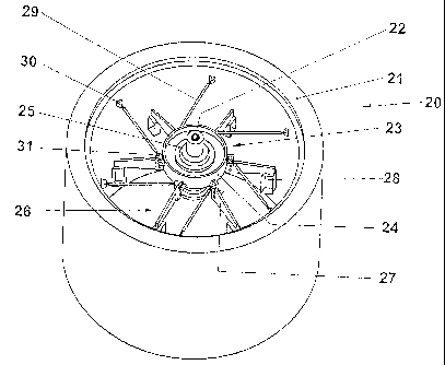
fig. 2 in a perspective view obliquely from above.
Shown in the figure is the (top) combined axial and
radial bearing 23 of a hydrogenerator 20, which is
surrounded by a hollow-cylindrical, annular foundation
21 made of concrete. Part of the shaft 22 of the rotor
extends through the combined axial and radial bearing
23, which is open at the top. The active rotor part is
flange-mounted on this part of the shaft 22 by means of
a flange 32 (fig. 3), which is arranged below the
bearing 23. The combined axial and radial bearing 23
comprises a radial bearing 25 and an axial bearing
(which cannot be seen in figs 2 and 3) arranged
underneath. Both bearings are arranged in a bearing
body 24, which is defined on the outside by an annular
outer shell.
Six supporting arms 27 are attached to the bearing body
24 in the bottom region of the axial bearing in a star-
shaped manner and such as to be directed radially
outward. It is of course not absolutely necessary for
these supporting arms to be oriented strictly radially,
as shown in the example. Each of the supporting arms 27
comprises a perpendicular metal plate 33 which tapers
outward and is screwed to an associated rib 34. The
ribs 34 in turn are welded to the bearing body 24 such
as to partly reach under the latter. Arranged
underneath on the outer ends of the supporting arms 27
are mounting elements 28, with which the supporting
arms 27 are mounted on the top side of the stator. The
mounting elements 28 are designed to be bendable in the
radial direction. In the case of the elements shown by
way of example in figs 2 and 3, this is achieved by two
perpendicular, parallel sheet-metal strips which are
arranged one behind the other in the radial direction
CA 02436577 2003-07-28
9 -
and are connected to one another at the top and bottom
in each case by a horizontal plate. However, the
mounting elements may of course also be elastomeric
cushions or other construction elements suitable for
performing the function. The supporting arms 27
together with the bearing body 24 form a star-shaped
bearing bracket 26 which passes the axial forces which
act on the axial bearing into the foundation 21 via a
stator (not shown for the sake oi clarity). The
mounting elements 28 bendable in the radial direction
ensure that the movements which arise during thermal
expansion of the star-shaped bearing bracket 26 are
absorbed and the loading and deformation of the bearing
body 24 are kept small. Likewise, the supporting arms
are designed in such a way that the axial bearing also
has only slight rigidity in the circumferential
direction.
On the other hand, the exact positioning of the bearing
body 24 or of the shaft 22 with regard to the axis of
rotation is carried out in the bearing arrangement
according to figs 2 and 3 by articulated struts 29 (six
in the example) adjustable in length. In contrast to
the designs realized hitherto, this has the advantage
that it is possible to adjust the centering even in the
ready assembled state. By means of bearing blocks 30,
31, the articulated struts 29, at the level of the
radial bearing 25, are pivotably linked with the inner
end to the outer shell of the bearing body 24 and with
the outer end to the inside of the foundation 21. The
articulated struts 29 are oriented tangentially to an
imaginary circle arranged concentrically to the shaft
22, so that an expansion of the bearing body 24 is
converted into a rotation about the axis of rotation of
the machine. The articulated struts 29 are designed
such as to be adjustable in length like a turnbuckle by
means of a combination of a right-hand and a left-hand
thread. It is thereby possible, in a simple manner and
CA 02436577 2003-07-28
- 10 -
at any time, to not only center or recenter the rotor
or the shaft with regard to the axis of rotation but to
also build up symmetrical or asymmetrical prestresses
which advantageously influence the running properties
of the rotor, in particular with regard to vibration
frequencies. Furthermore, the articulated struts 29
have the advantage that they are obtainable as
commercially available components and, compared with
complicated welded constructions, are comparatively
light and space-saving. Suitable articulated struts are
offered, for example, by the German company Lisega
GmbH, Zeven, under the type designation 39.
The bearing arrangement according to the invention is
distinguished overall by the following properties and
special features:
- the functions of supporting and positioning are
separate;
- support is still carried out by supporting arms;
- the supporting arms are arranged radially;
- the supporting arms are mounted on the outside on
bendable elements on the stator; the thermal
expansion is absorbed here, so that the bearing
body is not loaded and deformed to an excessive
degree;
the exact positioning of the bearing body or of
the shaft is effected by articulated struts;
the articulated struts are fastened to the bearing
body and to the foundation in a tangentially
oriented manner at articulation points, so that
the thermal expansion is easily converted into a
rotary movement;
the radial supporting arms have low rigidity in
the circumferential direction in such a way that
the rotary movement of the bearing body is
impaired as little as possible;
radial forces are passed vi.a the articulated
struts directly into the foundation;
CA 02436577 2003-07-28
- 11 -
the articulated struts are easily adjustable in
length; as a result, the exact positioning of the
shaft is readily possible; any requisite
subsequent correction to the shaft position is
also possible without any problems; and
the adjustable articulated struts permit the
setting of a predetermined prestress of the
bearing arrangement.
CA 02436577 2003-07-28
- 12 -
LIST OF DESIGNATIONS
10, 20 Hydrogenerator
11 Rotor
12, 22 Shaft
13 Supporting ring
14 Axial bearing (supporting bearing)
15, 16 Radial bearing (guide bearing)
17 Turbine
18 Combined axial and radial bearing
19 Axis
20 Radial/axial bearing unit
21 Foundation
22 Shaft
23 Combined axial and radial bearing
24 Bearing body
25 Radial bearing
26 Star-shaped bearing bracket
27 Supporting arm
28 Mounting element (bendable in the radial
direction)
29 Articulated strut (adjustable in length)
30, 31 Bearing block
32 Flange
33 Metal plate
34 Rib