Note: Descriptions are shown in the official language in which they were submitted.
CA 02436698 2003-07-29
WO 02/061232 PCT/US02/02464
THRU-TUBING STACKAGLE PERFORATING
GUN SYSTEM AND METHOD FOR USE
INVENTORS: JAMES A. ROCHEN; KARE-JONNY HAUGVALDSTAD
TIM W. SAMPSON
BACKGROUND OF THE INVENTION
1. Field of the Invention
This invention relates to apparatus and methods for perforating wells, and
more particularly, to a stackable gun system and method of use utilizing a
plurality of perforating guns which may be individually positioned in a
wellbore
and individually removed therefrom.
2. Description of the Related Art
In the past, perforating systems for use in completing or reworking wells
have been run into wells on a pipe string or wire line and positioned and
supported on a hanger. Another method for positioning the perforating
assembiies entails running them into the well on a slick line and lowering
them to
the desired position in the well, where they are anchored to the well casing.
The
slick line is typically detached and removed from the perforating assembly
before
the perforating operation.
It is preferable to seat one or more perforating guns on a hanger or anchor
that has been lowered and set in the casing at the desired depth. After the
perforating guns are in position, the lowering equipment can be removed from
the vicinity of the perforation, or from the well entirely. Thus the amount of
unnecessary equipment in the vicinity of the perforation is minimized.
Conventional hangers, however, must be run into the well before any
tubing string is installed because the hangers are typically too large to pass
through a tubing string. If a tubing string is already in place in a well, as
in the
case of a well being reworked, it is difficult to position a hanger in the
casing
below the end of the tubing string without first removing the tubing string.
1
CA 02436698 2003-07-29
WO 02/061232 PCT/US02/02464
Removal of the tubing string is undesirable, particufarly in cases where tfie
tubing
string comprises expensive pipe and/or connections and it is preferred to keep
the handling of the string to a minimum. In such cases, a wireline which can
be
either a slick line or a braided electric line can be used to lower individual
perforating guns through the tubing to the desired depth. The disadvantage to
using a wireline is that each gun is fired separately, resulting in pressure
and flow
from the formation begin as soon as the first gun is fired. This can greatly
prolong the perforating operation.
Hence, there is a need for stackable perforating gun system that can be
run through the production tubing, anchored in the larger casing below the end
of
the tubing string, fired as a unit and retrieved from the well after firing.
The system should be able to support several perforating guns, so that a
desired length of pipe can be perforated simultaneously. The system, including
the hanger and the individual gun sections, should also be self-centering in
the
casing, with the centralizers also being passable through the tubing string.
If the
gun system components do not centralize in the casing, it will be difficult or
impossible to mate the individual sections for proper operation.
After perforation, the perforating guns can either be retrieved or dropped
to the bottom of the well, depending on several factors. Hence, a support
should
be adaptable either to maintain its position in the casing or to release
itself from
the casing and drop to the bottom upon perforation. Other objects and
advantages of the invention will appear from the following description.
SUMMARY OF THE INVENTION
The present invention provides a stackable perforating gun system in
which a plurality of gun sections or sections may be individually run through
production tubing, positioned in a wellbore, fired as a unit, and individually
retrieved, as necessary. This tool can be run on coiled tubing, slick line or
braided electrical wireline.
2
CA 02436698 2006-12-21
The stackable perforating gun system of the present invention may be
described as a well perforating apparatus comprising a through tubing
retrievable bridge plug engagable with a portion of a cased wellbore for
providing a gun support within the wellbore, and a plurality of perforating
gun
sections, one of the gun sections being supported by the retrievable bridge
plug. The remainder of the gun sections are supported by an adjacent gun
section. Each gun section is centralized at each end with a coil spring
actuated folding arm type centralizer which is passable in either direction,
through the production tubing.
In one embodiment, the bridge plug is an automatically releasing
bridge plug.
Accordingly, in one aspect of the present invention there is provided a
method of perforating a casing of a well below a smaller diameter production
tubing string, comprising the steps of:
conveying a through-tubing retrievable bridge plug through the
production tubing string into the casing;
setting the through-tubing retrievable bridge plug into engagement
with the casing;
lowering a first perforating gun section through the tubing;
landing the first perforating gun section onto the through-tubing
retrievable bridge plug;
lowering at least one additional perforating gun section through the
production tubing;
landing the first at least one additional perforating gun section onto the
first perforating gun section;
lowering a firing head on to a top perforating gun section;
firing said perforating gun sections and perforating the casing;
releasing said through-tubing retrievable bridge plug from engagement
with the casing after firing the perforating gun sections; and
retrieving the through-tubing retrievable bridge plug from the casing
through the production tubing.
3
CA 02436698 2006-12-21
The step of lowering an additional perforating gun section into the
casing may be repeated as many times as necessary or desired. That is, the
additional perforating gun section may be one of the plurality of additional
perforating gun sections, each of the additiorial gun sections being supported
on an adjacent perforating gun section.
The method may further comprise a step of retrieving at least one of
the perforating gun sections from the casing and may further comprise a step
of retrieving the retrievable bridge plug.
The method may further comprise releasing the bridge plug from
engagement with the casing after firing the perforating gun sections, thereby
allowing the gun system to drop to the bottorri of the hole.
According to another aspect of the present invention there is provided
a well perforating apparatus for perforating a casing of a well below a
smaller
diameter production tubing string comprising:
a cased wellbore;
a production tubing disposed in said wellbore;
a through-tubing retrievable bridge plug engagable with a portion of a
well casing below said production tubing for providing a gun support within
the
casing;
a plurality of perforating gun sections, wherein one of said gun
sections is a lower gun section being supported by the through-tubing
retrievable bridge plug, and the remainder of said gun sections are supported
by an adjacent gun section; and
a firing head for activating said gun sections.
Examples of the more important features of the invention thus have
been summarized rather broadly in order that the detailed description
4
CA 02436698 2006-12-21
thereof that follows may be better understood, and in order that the
contributions to the art may be appreciated. There are, of course, additional
features of the invention that will be described hereinafter and which will
form
the subject of the claims appended hereto.
BRIEF DESCRIPTION OF THE DRAWINGS
For detailed understanding of the present invention, references should
be made to the following detailed description of the preferred embodiment,
taken in cnjunction with the accompanying drawings, in which like elements
have been given like numerals and wherein:
Figure 1 is a schematic of a production wellbore with a stackable
perforating gun systerri installed;
Figure 2 is a schematic of one embodiment of a stackable perforating
gun system; and,
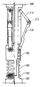
Figure 3 is a schematic of a coil spring activated centralizer
mechanism according to one embodiment.
DESCRIPTION OF THE PREFERRED EMBODIMENT
Advances in technology relating to workover of producing oil and gas
wells have greatly enhanced the efficiency and economy of workover
operations. Some workover operations cari now be performed through a
production string of a flowing oil and gas well. Previously, it was typical to
remove the production tubing string to perform workover operations. This
process of removing the production tubing is expensive, complicated, and
time-consuming.
4a
CA 02436698 2003-07-29
WO 02/061232 PCT/US02/02464
Figure 1 shows a schematic diagram of a thru-tubing stackable gun
system 7 deployed in a producing wellbore 5. The wellbore 5 has steel casing
100 which is cemented into the wellbore 5 using techniques known in the art of
completion of wellbores.
The casing 100 extends from the wellhead 115 at the surface downward
past the area to be worked over. Disposed within the casing 100 is at least
one
string of production tubing 110. The production tubing 110 is positioned in
the
wellbore by packers 105 seal off between the production tubing 110 and the
casing 100 such that all production flow 112 is constrained to flow through
the
production tubing 110 to the surface. Such packers are known in the art and
are
not discussed in detail here.
A thru-tubing retrievable bridge plug 10 such as Baker Oil Tools Product
No. H340-10, is run through the tubing 110 and set within the casing 100 near
the bottom of the reservoir zone to be perforated.
The perforating gun system 7 operatively engages and is supported by the
bridge plug 10. The gun system 7 comprises a plurality of gun assemblies, or
sections. The lowermost gun section 50 comprises an upper centralizer 25 and a
lower centralizer 15 for centralizing the gun 20 in the casing 100. The lower
centralizer 15 is adapted to mate with the top of the bridge plug 10, using a
collet
type latching system known in the art.
At least one second gun section 55a is adapted to operatively connect
with upper centralizer 25, as shown in Figure 2. Second gun section 55a is
operatively connected to lower gun section 50 so that when the upper gun
section is fired, the lower gun section is fired sequentially. The operative
connection between the gun sections is of a kind known in the art. The second
gun section has a top centralizer 25 identical to the one on top of the lower
gun
section 50. Multiple gun sections 55a-55n may be stacked above lower gun
section 50 and supported by bridge plug 10. The exact number of additional gun
5
CA 02436698 2003-07-29
WO 02/061232 PCT/US02/02464
sections will vary depending on the well conditions and' the size ofthe
formation
to be perforated.
Figure 3 is a schematic of the coil spring activated centralizer mechanism
used in centralizers 15, 25, 30, and 35. The centralizer mechanism is the same
in
all of the centralizers with the centralizer ends being appropriately adapted
to
mate with other gun system components as necessary. The centralizer
mechanism comprises an upper body 180 and a lower body 150 which are
screwed together. A sliding spring cap 165 is sized to slide on the upper body
180. A coil spring 160 is captured between the sliding cap 165 and the spring
stop 150. At least three equally spaced upper arms 175 are rotatably attached
to
the upper body 180. At least three lower arms 170 are rotatably attached to
the
sliding cap 165 and are pinned to the upper arms 175 at pin joint 173 using
standard mechanical fastening techniques known in the art. When the
1s centralizer mechanism is assembled, the coil spring 160 is preloaded such
that
when the arms 170, 175 are in there extended position, as shown in Figure 3,
there is sufficient force transmitted to the pivoted arms of the plurality of
centralizers to maintain the gun system 7 centralized in the casing 100. When
the
centralizer is moving through the tubing, the arms are compressed inwardly
forcing the sliding cap 165 downward and further compressing the spring 160.
As
the centralizers pass through the bottom of the tubing 110, the spring 160
forces
the cap 165 to slide upwards forcing the pivoted arms to extend outward into
contact with the casing 100.
A firing head assembly 60 is attached to the topmost gun section 55n.
The firing head assembly 60 comprises a firing head 40 and a centralizer 35.
The centralizer 35 is adapted on its lower end to operatively attach to the
top of
gun section 55n and on its top end to operatively attach to firing head 40.
Firing
head 40 is a hydraulic pressure actuated type firing head of a kind known in
the
art and is adapted on its lower end to attach to centralizer 35, and on its
upper
end to attach to a slickline 130 for insertion and retrieval into the wellbore
5.
6
CA 02436698 2003-07-29
WO 02/061232 PCT/US02/02464
In operation, the bridge plug 10 is run through the small diamefer tubing
110 and into the larger diameter casing 100 and set at the desired location
using
techniques known in the art. The bridge plug 10 uses internal hydraulic
pressure
to expand elastomeric elements into contact with the casing 100 with
sufficient
force so as to be able to support the weight of the stackable gun system 7.
Once
the bridge plug 10 is set, the lower gun section 50 is run in using a
slickline 130.
The lower gun is latched to the top of the bridge plug 10 and the slickline
130 is
released and retracted to the surface using the reel 135. Next, the gun
section
55a is run in and latched to the top of the lower gun section 50. Additional
gun
sections 55 are run in and latched onto the top of the previous gun 55 as is
required for the particular formation. The topmost gun section 55n is attached
to
a pressure actuated firing head assembly 60 and is run in and operatively
latched
to the top of the gun string 7. In the preferred embodiment, a pressure
actuated
firing head of a type known in the art is used to initiate the firing. In
another
is embodiment, electric wireline operated firing heads may be used to initiate
firing.
The firing of the firing head 40 causes sequential firing of each of the gun
sections, such as 55n-55a and 50.
The bridge plug 10 includes an automatic release such that the bridge
plug 10 internal pressure is released upon firing of the bottom gun section
50.
This releases the bridge plug 10 from engagement with the wall of the casing
100
and allows the bridge plug 10 and gun system 7 to fall to the bottom of the
wellbore 5 providing unimpeded flow through the just perforated casing 100.
The gun system 7 may be retrieved from the wellbore one gun section at a
time by lowering a standard retrieval tool into the wellbore and connecting to
the
uppermost gun section so that this gun section may be raised out of the
wellbore.
The connections between the individual gun sections are spring adapted to
release one section at a time. Each of the gun sections may be removed in the
same manner.
The foregoing description is directed to particular embodiments of the
present invention for the purpose of illustration and explanation. It will be
7
CA 02436698 2003-07-29
WO 02/061232 PCT/US02/02464
apparent, however, to one skilled in the art that many modifications and
changes
to the embodiment set forth above are possible without departing from the
scope
and the spirit of the invention. It is intended that the following claims be
interpreted to embrace all such modifications and changes.
8