Note: Descriptions are shown in the official language in which they were submitted.
CA 02436880 2003-08-08
MASS SPECTROMETER
The present invention relates to a mass
spectrometer and a method of mass spectrometry. The
preferred embodiment relates to 3D quadrupole ion traps
("QIT") and Time of Flight ("TOF") mass analysers.
Known 3D (Paul) quadrupole ion trap mass
spectrometers comprise a doughnut shaped central ring
electrode and two end-cap electrodes. Such known 3D
(Paul) quadrupole ion trap mass spectrometers typically
have a relatively low resolution and a relatively low
mass measurement accuracy when scanning the complete
mass range compared with other types of mass
spectrometers such as magnetic sector and Time of Flight
mass spectrometers. 3D quadrupole ion traps do however
exhibit a relatively high sensitivity in both MS and
MS/MS modes of operation. One particular problem with
3D quadrizpole ion traps is that they suffer from having
a relatively limited mass range and exhibit a low mass
to charge ratio cut-off limit below which ions cannot be
stored within the quadrupole ion trap. In a MS/MS mode
of operation only about a 3:1 ratio of parent mass to
fragment mass can be stored and recorded.
Orthogonal acceleration Time of Flight mass
spectrometers have relatively higher resolving powers
and higher mass measurement accuracy for both MS and
MS/MS modes. Typically, orthogonal acceleration Time of
Flight mass spectrometers are coupled to ion sources
which provide a continuous beam of ions. Segments of
this continuous ion beam are then orthogonally extracted
for subsequent mass analysis. However, about 750 of the
ions are not extracted for mass analysis and are thus
lost.
CA 02436880 2003-08-08
- 2 -
It is therefore desired to address the mass range
limitation inherent with conventional quadrupole ion
traps and to increase the duty cycle of an orthogonal
acceleration Time of Flight mass analyser when
performing MS and MS/MS experiments.
According to the present invention there is
provided a mass spectrometer comprising:
a first ion trap and a second ion trap wherein the
first ion trap is arranged to have, in use, a first low
mass cut-off and the second ion trap is arranged to
have, in use, a second low mass cut-off, the second low
mass cut-off being lower than the first low mass cut-off
so that at least some ions having mass to charge ratios
lower than the first low mass cut-off which are not
trapped in the first ion trap are trapped in the second
ion trap.
Advantageously, the combination of two or more ion
traps in series having different low mass cut-offs
increases the overall ion trapping volume or capacity
and hence the dynamic range of the ion trapping system.
A mass spectrometer according to the preferred
embodiment is capable of performing both MS and MS/MS
modes of operation and comprises an ion source, a series
of coupled quadrupole ion traps and an orthogonal
acceleration Time of Flight mass analyser. The
combination of multiple quadrupole ion traps and the
orthogonal acceleration Time of Flight mass analyser
provides a mass spectrometer with an increased mass
range (especially in MS/MS), increased sensitivity,
increased mass measurement accuracy and increased mass
resolution compared with other known arrangements.
According to a less preferred embodiment fragment
ions may be generated externally to the first ion trap
CA 02436880 2003-08-08
- 3 -
by surface induced disassociation (SID), collision
induced disassociation (CID) or post source decay (PSD)
and then transferred to the first ion trap.
According to the preferred embodiment collisional
cooling with a bath gas may be employed in one or more
of the ion traps and/or in the transfer regions)
between the ion traps. Collisional cooling
advantageously reduces both the kinetic energy of the
ions and the spread of kinetic energies of the ions.
Collisional cooling also has the effect of improving the
trapping efficiency within the ion trap whilst preparing
the ions for subsequent mass analysis in a Time of
Flight mass analyser, preferably an orthogonal
acceleration Time of Flight mass analyser, which may
optionally include a reflectron.
The first ion trap preferably comprises a
quadrupole ion trap. According to the one embodiment
the first ion trap comprises a 3D (Paul) quadrupole ion
trap comprising a ring electrode and two end-cap
electrodes, the ring electrode and the end-cap
electrodes having a hyperbolic surface.
According to another embodiment the first ion trap
comprises one or more cylindrical ring electrodes and
two substantially planar end-cap electrodes.
According to another embodiment the first ion trap
comprises one, two, three or more than three ring
electrodes and two substantially planar end-cap
electrodes.
One of the end-cap electrodes may comprise a sample
or target plate. The sample or target plate may
comprise a substrate with a plurality of sample regions
arranged preferably in a microtitre format wherein, for
example, the pitch spacing between samples is
CA 02436880 2003-08-08
- 4 -
approximately or exactly 18 mm, 9 mm, 4.5 mm, 2.25 mm or
1.125 mm. Up to or at least 48, 96, 384, 1536 or 6144
samples may be arranged to be received on the sample or
target plate. A laser beam or an electron beam is
preferably targeted in use at the sample or target
plate.
One of the end-cap electrodes of the first ion trap
may comprise a mesh or grid.
The first ion trap may comprise a 2D (linear)
quadrupole ion trap comprising a plurality of rod
electrodes and two end electrodes.
According to other less preferred embodiments the
first ion trap may comprise a segmented ring set
comprising a plurality of electrodes having apertures
through which ions are transmitted or a Penning ion
trap.
A first AC or RF voltage having a first amplitude
is preferably
applied
to the
first ion
trap. The
first
ampli tude is preferably selected from the group
consi sting of: (i) 0-250 V~,P; (ii) 250-500 VE,E,; (iii)
500-750
VPP; (iv)
750-1000
VPp; (v)
1000-1250
VPp; (vi)
1250- 1500 VpP; (vii) 1500-1750 VPp; (viii) 1750-2000
VPP;
(ix) 2000-2250 VpP; (x) 2250-2500 VPp; (xi) 2500-2750
VpP;
(xii) 2750-3000 VPp; (xiii) 3000-3250 VPp; (xiv) 3250-
3500 VPp; (xv) 3500-3750 VPp; (xvi) 3750-4000 Vpp; (xvii)
4000- 4250 VPp; (xviii) 4250-4500 VPp; (xix) 4500-4750
Vpp;
(xx) 4750-5000 VPp; (xxi) 5000-5250 VpP; (xxii) 5250-5500
Vpp; (xxiii) 5500-5750 VPp; (xxiv) 5750-6000 VPp; (xxv)
6000- 6250 VpP; (xxvi) 6250-6500 Vpp; (xxvii) 6500-6750
Vpp; (xxviii) 6750-7000 VPp; (xxix) 7000-7250 Vpp; (xxx)
7250- 7500 VPP; (xxxi) 7500-7750 VPp; (xxxii) 7750-8000
Vpp; (xxxiii) 8000-8250 Vpp; (xxxiv) 8250-8500 Vpp; (xxxv)
8500- 8750 VPP; (xxxvi) 8750-9000 VpP; (xxxvii) 9250-9500
CA 02436880 2003-08-08
- 5 -
Vpp; (xxxviii) 9500-9750 Vpp; (xxxix) 9750-10000 VPP; and
(X1) >lOOOO VPp.
The first AC or RF voltage preferably has a
frequency within a range selected from the group
consisting of: (i) < 100 kHz; (ii) 100-200 kHz; (iii)
200-400 kHz; (iv) 400-600 kHz; (v) 600-800 kHz; (vi)
800-1000 kHz; (vii) 1.0-1.2 MHz; (viii) 1.2-1.4 MHz;
(ix) 1.4-1.6 MHz; (x) 1.6-1.8 MHz; (xi) 1.8-2.0 MHz; and
(xii) > 2.0 MHz.
The second ion trap preferably comprises a
quadrupole ion trap.
The second ion trap may comprise a 3D (Paul)
quadrupole ion trap comprising a ring electrode and two
end-cap electrodes, the ring electrode and the end-cap
electrodes having a hyperbolic surface. Alternatively,
the second ion trap may comprise a cylindrical ring
electrode and two substantially planar end-cap
electrodes.
The second ion trap may comprise one, two, three or
more than three ring electrodes and two substantially
planar end-cap electrodes. One or more of the end-cap
electrodes of the second ion trap may comprise a mesh or
grid.
According to another embodiment the second ion trap
may comprise a 2D (linear) quadrupole ion trap
comprising a plurality of rod electrodes and two end
electrodes.
According to less preferred embodiments the second
ion trap may comprise a segmented ring set comprising a
plurality of electrodes having apertures through which
ions are transmitted or a Penning ion trap.
A second AC or RF voltage having a second amplitude
is preferably applied to the second ion trap. The
CA 02436880 2003-08-08
- 6 -
second amplitude is preferably selected from the group
consisting of: (i) 0-250 VPp; (ii) 250-500 Vpp; (iii)
500-750 VpP; (iv) 750-1000 Vpp; (v) 1000-1250 Vpp; (vi)
1250-1500 Vpp; (vii) 1500-1750 Vp~,; (viii) 1750-2000 V~,~,;
(ix) 2000-2250 VPP; (x) 2250-2500 VpP; (xi) 2500-2750 Vpp;
(xii) 2750-3000 VPP; (xiii) 3000-3250 VPP; (xiv) 3250-
3500 Vpp; (xv) 3500-3750 VPP; (xvi) 3750-4000 Vpp; (xvii)
4000-4250 Vpp; (xviii) 4250-4500 VPp; (xix) 4500-4750 Vpp;
(xx) 4750-5000 VPP; (xxi) 5000-5250 Vpp; (xxii) 5250-5500
VpP; (xxiii) 5500-5750 VPp; (xxiv) 5750-6000 Vpp; (xxv)
6000-6250 Vpp; (xxvi) 6250-6500 VPP; (xxvii) 6500-6750
VpP; (xxviii) 6750-7000 Vpp; (xxix) 7000-7250 Vpp; (xxx)
7250-7500 Vpp; (xxxi) 7500-7750 VPP; (xxxii) 7750-8000
Vpp; (xxxiii) 8000-8250 Vpp; (xxxiv) 8250-8500 VPp; (xxxv)
8500-8750 VPP; (xxxvi) 8750-9000 Vpp; (xxxvii) 9250-9500
VpP; (xxxviii) 9500-9750 VPP; (xxxix) 9750-10000 VpP; and
(x1) >10000 Vpp.
The second AC or RF voltage preferably has a
frequency within a range selected from the group
consisting of: (i) < 100 kHz; (ii) 100-200 kHz; (iii)
200-400 kHz; (iv) 400-600 kHz; (v) 600-800 kHz; (vi)
800-1000 kHz; (vii) 1.0-1.2 MHz; (viii) 1.2-1.4 MHz;
(ix) 1.4-1.6 MHz; (x) 1.6-1.8 MHz; (xi) 1.8-2.0 MHz; and
(xii) > 2.0 MHz.
The amplitude of an AC or RF voltage applied to the
first ion trap is preferably greater than the amplitude
of an AC or RF voltage applied to the second ion trap.
The amplitude of an AC or RF voltage applied to the
first ion trap is preferably greater than the amplitude
of an AC or RF voltage applied to the second ion trap by
at least x VPp and wherein x is selected from the group
consisting of: (i) 5; (ii) 10; (iii) 20; (iv) 30; (v)
40: (vi) 50; (vii) 60; (viii) 70; (ix) 80; (x) 90; (xi)
CA 02436880 2003-08-08
100; (xii) 110; (xiii) 120; (xiv) 130; (xv) 140; (xvi)
150; (xvii) 160; (xviii) 170; (xix) 180; (xx) 190; (xxi)
200; (xxii) 250; (xxiii) 300; (xxiv) 350; (xxv) 400;
(xxvi) 450; (xxvii) 500; (xxviii) 550; (xxix) 600; (xxx)
650; (xxxi) 700; (xxxii) 750; (xxxiii) 800; (xxxiv) 850;
(xxxv) 900; (xxxvi) 950; and (xxxvii) 1000.
The first ion trap and/or the second ion trap are
preferably maintained at a pressure selected from the
group consisting of: (i) greater than or equal to 0.0001
mbar; (ii) greater than or equal to 0.0005 mbar; (iii)
greater than or equal to 0.001 mbar; (iv) greater than
or equal to 0.005 mbar; (v) greater than or equal to
0.01 mbar; (vi) greater than or equal to 0.05 mbar;
(vii) greater than or equal to 0.1 mbar; (viii) greater
than or equal to 0.5 mbar; (ix) greater than or equal to
1 mbar; (x) greater than or equal to 5 mbar; and (xi)
greater than or equal to 10 mbar.
The first ion trap and/or the second ion trap are
preferably maintained at a pressure selected from the
group consisting of: (i) less than or equal to 10 mbar;
(ii) less than or equal to 5 mbar; (iii) less than or
equal to 1 mbar; (iv) less than or equal to 0.5 mbar;
(v) less than or equal to 0.1 mbar; (vi) less than or
equal to 0.05 mbar; (vii) less than or equal to 0.01
mbar; (viii) less than or equal to 0.005 mbar; (ix) less
than or equal to 0.001 mbar; (x) less than or equal to
0.0005 mbar; and (xi) less than or equal to 0.0001 mbar.
The first ion trap and/or the second ion trap are
preferably maintained, in use, at a pressure selected
from the group consisting of: (i) between 0.0001 and 10
mbar; (ii) between 0.0001 and 1 mbar; (iii) between
0.0001 and 0.1 mbar; (iv) between 0.0001 and 0.01 mbar;
(v) between 0.0001 and 0.001 mbar; (vi) between 0.001
CA 02436880 2003-08-08
-
and 10 mbar; (vii) between 0.001 and 1 mbar; (viii)
between 0.001 and 0.1 mbar; (ix) between 0.001 and 0.01
mbar; (x) between 0.01 and 10 mbar; (xi) between 0.01
and 1 mbar; (xii) between 0.01 and 0.1 mbar; (xiii)
between 0.1 and 10 mbar; (xiv) between 0.1 and 1 mbar;
and (xv) between 1 and 10 mbar.
According to other embodiments further ion traps
may be provided in series with the first and second ion
traps. Accordingly, a third ion trap may be provided
and which is arranged to have, in use, a third low mass
cut-off, the third low mass cut-off being lower than the
second low mass cut-off so that at least some ions
having mass to charge ratios lower than the first and
second mass cut-offs which are not trapped in the first
and second ion traps are trapped in the third ion trap.
A third AC or RF voltage having a third amplitude
may be applied to the third ion trap. The third
amplitude is preferably selected from the group
consisting of: (i) 0-250 Vpp; (ii) 250-500 VpP; (iii)
500-750 Vpp; (iv) 750-1000 VpP; (v) 1000-1250 VPp; (vi)
1250-1500 VPp; (vii) 1500-1750 Vpp; (viii) 1750-2000 VPp;
(ix) 2000-2250 VPP; (x) 2250-2500 VPp; (xi) 2500-2750 Vpp;
(xii) 2750-3000 VPp; (xiii) 3000-3250 Vpp; (xiv) 3250-
3500 VPP; (xv) 3500-3750 VpP; (xvi) 3750-4000 VPP; (xvii)
4000-4250 Vpp; (xviii) 4250-4500 VPP; (xix) 4500-4750 VPp;
(xx) 4750-5000 Vpp; (xxi) 5000-5250 VPp; (xxii) 5250-5500
VPp; (xxiii) 5500-5750 Vpp; (xxiv) 5750-6000 VPp; (xxv)
6000-6250 VPP; (xxvi) 6250-6500 Vpp; (xxvii) 6500-6750
VPP; (xxviii) 6750-7000 VPp; (xxix) 7000-7250 VPP; (xxx)
7250-7500 VPP; (xxxi) 7500-7750 VpP; (xxxii) 7750-8000
VPP; (xxxiii) 8000-8250 VPp; (xxxiv) 8250-8500 Vpp; (xxxv)
8500-8750 VPP; (xxxvi) 8750-9000 VpE,; (xxxvii) 9250-9500
CA 02436880 2003-08-08
- 9 -
Vpp; (xxxviii) 9500-9750 Vpp; (xxxix) 9750-10000 Vpp; and
(x1) >lOOOO Vpp.
The third AC or RF voltage preferably has a
frequency within a range selected from the group
consisting of: (i) < 100 kHz; (ii) 100-200 kHz; (iii)
200-400 kHz; (iv) 400-600 kHz; (v) 600-800 kHz; (vi)
800-1000 kHz; (vii) 1.0-1.2 MHz; (viii) 1.2-1.4 MHz;
(ix) 1.4-1.6 MHz; (x) 1.6-1.8 MHz; (xi) 1.8-2.0 MHz; and
(xii) > 2.0 MHz.
The amplitude of an AC or RF voltage applied to the
second ion trap is preferably greater than the third
amplitude.
A fourth ion trap may be provided and which is
preferably arranged to have, in use, a fourth low mass
cut-off, the fourth low mass cut-off being lower than
the third low mass cut-off so that at least some ions
having mass to charge ratios lower than the first,
second and third mass cut-offs which are not trapped in
the first, second and third ion traps are trapped in the
fourth ion trap.
A fourth AC or RF voltage having a fourth amplitude
is preferably applied to the fourth ion trap. The
fourth amplitude is preferably selected from the group
consisting of: (i) 0-250 Vpp; (ii) 250-500 Vpp; (iii)
500-750 Vpp; (iv) 750-1000 Vpp; (v) 1000-1250 Vpp; (vi)
1250-1500 Vpp; (vii) 1500-1750 Vpp; (viii) 1750-2000 Vpp;
(ix) 2000-2250 Vpp; (x) 2250-2500 Vpp; (xi) 2500-2750 Vpp;
(xii) 2750-3000 Vpp; (xiii) 3000-3250 Vpp; (xiv) 3250-
3500 Vpp; (xv) 3500-3750 Vpp; (xvi) 3750-4000 Vpp; (xvii)
4000-4250 Vpp; (xviii) 4250-4500 Vpp; (xix) 4500-4750 Vpp;
(xx) 4750-5000 Vpp; (xxi) 5000-5250 Vpp; (xxii) 5250-5500
Vpp; (xxiii) 5500-5750 Vpp; (xxiv) 5750-6000 Vpp; (xxv)
6000-6250 Vpp; (xxvi) 6250-6500 Vpp; (xxvii) 6500-6750
CA 02436880 2003-08-08
- 10 -
VPp; (xxviii) 6750-7000 Vpp; (xxix) 7000-7250 VPP; (xxx)
7250-7500 Vpp; (xxxi) 7500-7750 Vpp; (xxxii) 7750-8000
VpP; (xxxiii) 8000-8250 Vpp; (xxxiv) 8250-8500 Vpp; (xxxv)
8500-8750 VPp; (xxxvi) 8750-9000 Vpp; (xxxvii) 9250-9500
VPp; (xxxviii) 9500-9750 Vpp; (xxxix) 9750-10000 Vpp; and
(x1) >10000 VPp.
The fourth AC or RF voltage preferably has a
frequency within a range selected from the group
consisting of: (i) < 100 kHz; (ii) 100-200 kHz; (iii)
200-400 kHz; (iv) 400-600 kHz; (v) 600-800 kHz; (vi)
800-1000 kHz; (vii) 1.0-1.2 MHz; (viii) 1.2-1.4 MHz;
(ix) 1.4-1.6 MHz; (x) 1.6-1.8 MHz; (xi) 1.8-2.0 MHz; and
(xii) > 2.0 MHz.
The third amplitude is preferably greater than the
fourth amplitude.
According to other embodiments five, six, seven,
eight, nine, ten or more than ten ion traps may be
provided in series.
A continuous or pulsed ion source is preferably
provided. The ion source may comprise an Electrospray
ion source, an Atmospheric Pressure Chemical Ionisation
("APCI") ion source, an Atmospheric Pressure MALDI ion
source, an Electron Ionisation ("EI") ion source, a
Chemical Ionisation ("CI") ion source, a Field
Desorption Ionisation ("FI") ion source, a Matrix
Assisted Laser Desorption Ionisation ("MALDI") ion
source, a Laser Desorption Ionisation ("LDI") ion
source, a Laser Desorption/Ionisation on Silicon
("DIOS") ion source, a Surface Enhanced Laser Desorption
Ionisation ("SELDI") ion source or a Fast Atom
Bombardment ("FAB") ion source.
An ion detector may be arranged downstream of the
second ion trap. The ion detector may comprise an
CA 02436880 2003-08-08
- 11 -
electron multiplier, a photo-multiplier or a
channeltron.
A Time of Flight mass analyser, such as an axial
Time of Flight mass analyser or more preferably an
orthogonal acceleration Time of Flight mass analyser may
be provided.
In addition to the first, second and optionally
third, fourth etc. ion traps, a further ion trap is
preferably provided. The further ion trap preferably
comprises a quadrupole ion trap.
The further ion trap may comprise a 3D (Paul)
quadrupole ion trap comprising a ring electrode and two
end-cap electrodes, the ring electrode and the end-cap
electrodes having a hyperbolic surface.
The further ion trap may comprise one or more
cylindrical ring electrodes and two substantially planar
end-cap electrodes.
Alternatively, the further ion trap may comprise
one, two, three or more than three ring electrodes and
two substantially planar end-cap electrodes.
According to an embodiment one or more of the end-
cap electrodes of the further ion trap may comprise a
mesh or grid.
According to another embodiment the further ion
trap may comprise a 2D (linear) quadrupole ion trap
comprising a plurality of rod electrodes and two end
electrodes.
According to less preferred embodiments the further
ion trap may comprise a segmented ring set comprising a
plurality of electrodes having apertures through which
ions are transmitted or a Penning ion trap.
Ions are preferably pulsed out of the further ion
trap in a non mass-selective mode or non scanning mode.
CA 02436880 2003-08-08
- 12 -
For example, ions may be pulsed out of the further ion
trap by applying a DC voltage extraction pulse to the
end-cap electrodes of the further ion trap. A DC
voltage may also or alternatively be applied to the ring
electrodes) of the further ion trap so that a more
linear axial DC electric field gradient is provided.
Additional ion traps may be provided for storing
parent ions in MS/MS modes of operation. The mass
spectrometer may therefore further comprise a first
additional ion trap. The first additional ion trap
preferably comprises a quadrupole ion trap. The first
additional ion trap may comprise a 3D (Paul) quadrupole
ion trap comprising a ring electrode and two end-cap
electrodes, the ring electrode and the end-cap
electrodes having a hyperbolic surface.
Alternatively, the first additional ion trap may
comprise one or more cylindrical ring electrodes and two
substantially planar end-cap electrodes.
The first additional ion trap may comprise one,
two, three or more than three ring electrodes and two
substantially planar end-cap electrodes. One or more
end-cap electrodes of the first additional ion trap may
comprise a mesh or grid.
The first additional ion trap may comprise a 2D
(linear) quadrupole ion trap comprising a plurality of
rod electrodes and two end electrodes. Alternatively,
the first additional ion trap may comprise a segmented
ring set comprising a plurality of electrodes having
apertures through which ions are transmitted or a
Penning ion trap.
A second additional ion trap for storing parent
ions in MS/MS modes of operation may preferably be
provided. The second additional ion trap may comprise a
CA 02436880 2003-08-08
- 13 -
quadrupole ion trap. The second additional ion trap may
comprise a 3D (Paul) quadrupole ion trap comprising a
ring electrode and two end-cap electrodes, the ring
electrode and the end-cap electrodes having a hyperbolic
surface.
The second additional ion trap may comprise one or
more cylindrical ring electrodes and two substantially
planar end-cap electrodes. Alternatively, the second
additional ion trap may comprise one, two, three or more
than three ring electrodes and two substantially planar
end-cap electrodes. One or more end-cap electrode of
the second additional ion trap may comprise a mesh or
grid.
The second additional ion trap may comprise a 2D
(linear) quadrupole ion trap comprising a plurality of
rod electrodes and two end electrodes. Alternatively,
the second additional ion trap may comprise a segmented
ring set comprising a plurality of electrodes having
apertures through which ions are transmitted or a
Penning ion trap.
According to another aspect of the present
invention, there is provided a method of mass
spectrometry, comprising:
providing a first ion trap having a first low mass
cut-off;
providing a second ion trap having a second low
mass cut-off, the second low mass cut-off being lower
than the first low mass cut-off;
trapping some ions in the first ion trap; and
trapping in the second ion trap at least some ions
having mass to charge ratios lower than the first low
mass cut-off which are not trapped in the first ion
trap.
CA 02436880 2003-08-08
- 14 -
In the various embodiments contemplated in the
present application when a quadrupole ion trap is used
with multiple inner (or ring) electrodes (which are
simpler to manufacture than electrodes having an
hyperbolic surface) the quadrupole field may be
generated by applying different AC or RF voltage
amplitudes of the same phase to each inner electrode.
The inner electrodes should preferably be symmetrical
about the centre of the ion trap. However, by selecting
a certain aperture or inner radius for the ring
electrodes it is possible to generate an AC or RF
electric field which is close to quadrupolar with the
same amplitude and phase of AC or RF applied to each
ring electrode and with the opposing phase applied to
the end-cap electrodes.
If an ion trap with e.g. flat or thin cylindrical
electrodes has to pulse ions out of the ion trap (for
example, to pulse the ions into an axial or orthogonal
acceleration Time of Flight mass analyser) then the DC
voltages applied to the electrodes in such an ion
extraction mode can be arranged so that a substantially
linear electric field is generated. This may be
advantageous in terms of ion transfer efficiency. Also,
there may be some degree of time of flight spatial
focusing after pulsed extraction.
According to another aspect of the present
invention there is provided a mass spectrometer
comprising:
a quadrupole ion trap;
a further ion trap arranged to receive ions ejected
from the quadrupole ion trap; and
a Time of Flight mass analyser arranged to receive
ions ejected from the further ion trap;
CA 02436880 2003-08-08
- 15 -
wherein in a first mode of operation the further
ion trap receives a pulse of ions which have been mass-
selectively ejected from or scanned out of the
quadrupole ion trap, wherein the ratio of the maximum
mass to charge ratio of ions in the pulse of ions to the
minimum mass to charge ratio of ions in the pulse of
ions is a maximum of x, and wherein x _< 4.0, and wherein
the ions received from the quadrupole ion trap are
collisionally cooled within the further ion trap.
Preferably, x is selected from the group consisting
of: (i) 3.9; (ii) 3.8; (iii) 3.7; (iv) 3.6; (v) 3.5;
(vi) 3.4; (vii) 3.3; (viii) 3.2; (ix) 3.1; (x) 3.0; (xi)
2.9; (xii) 2.8; (xiii) 2.7; (xiv) 2.6; (xv) 2.5; (xvi)
2.4; (xvii) 2.3; (xviii) 2.2; (xix) 2.1; (xx) 2.0; (xxi)
1.9; (xxii) 1.8; (xxiii) 1.7; (xxiv) 1.6; (xxv) 1.5;
(xxvi) 1.4; (xxvii) 1.3; (xxviii) 1.2; and (xxix) 1.1.
In a first mode of operation the further ion trap
is preferably maintained at a pressure selected from the
group consisting of: (i) greater than or equal to 0.0001
mbar; (ii) greater than or equal to 0.0005 mbar; (iii)
greater than or equal to 0.001 mbar; (iv) greater than
or equal to 0.005 mbar; (v) greater than or equal to
0.01 mbar; (vi) greater than or equal to 0.05 mbar;
(vii) greater than or equal to 0.1 mbar; (viii) greater
than or equal to 0.5 mbar; (ix) greater than or equal to
1 mbar; (x) greater than or equal to 5 mbar; and (xi)
greater than or equal to 10 mbar.
In a first mode of operation the further ion trap
is preferably maintained at a pressure selected from the
group consisting of: (i) less than or equal to 10 mbar;
(ii) less than or equal to 5 mbar; (iii) less than or
equal to 1 mbar; (iv) less than or equal to 0.5 mbar;
(v) less than or equal to 0.1 mbar; (vi) less than or
CA 02436880 2003-08-08
- 16 -
equal to 0.05 mbar; (vii) less than or equal to 0.01
mbar; (viii) less than or equal to 0.005 mbar; (ix) less
than or equal to 0.001 mbar; (x) less than or equal to
0.0005 mbar; and (xi) less than or equal to 0.0001 mbar.
In a first mode of operation the further ion trap
is preferably maintained at a pressure selected from the
group consisting of: (i) between 0.0001 and 10 mbar;
(ii) between 0.0001 and 1 mbar; (iii) between 0.0001 and
0.1 mbar; (iv) between 0.0001 and 0.01 mbar; (v) between
0.0001 and 0.001 mbar; (vi) between 0.001 and 10 mbar;
(vii) between 0.001 and 1 mbar; (viii) between 0.001 and
0.1 mbar; (ix) between 0.001 and 0.01 mbar; (x) between
0.01 and 10 mbar; (xi) between 0.01 and 1 mbar; (xii)
between 0.01 and 0.1 mbar; (xiii) between 0.1 and 10
mbar; (xiv) between 0.1 and 1 mbar; and (xv) between 1
and 10 mbar.
In a second mode of operation ions are preferably
pulsed out of or ejected from the further ion trap in a
non mass-selective or a non-scanning manner i.e. ions
are not resonantly excited out of the further ion trap
and hence the ions are not ejected from the further ion
trap in a substantially excited state. In the second
mode of operation ions may be pulsed out of or ejected
from the further ion trap by applying one or more DC
voltage extraction pulses to the further ion trap. The
one or more DC extraction voltages may also be applied
to one or more end or end-cap electrodes of the further
ion trap and/or to one or more central or ring
electrodes of the further ion trap. Preferably, in the
second mode of operation AC or RF voltages are not
substantially applied to the electrodes of the further
ion trap.
CA 02436880 2003-08-08
- 17 -
In the second mode of operation the further ion
trap is preferably maintained at a lower pressure than
when the further ion trap is operated in the first mode
of operation. The further ion trap is preferably
maintained at a pressure selected from the following
group when operated in the second mode of operation: (i)
< 5x10 2 mbar; (ii) < 10 2 mbar; (iii) < 5x10 3 mbar; (iv)
< 10 3 mbar; (v) < 5x10 4 mbar; (vi) < 10 4 mbar; (vii) <
5x10 5 mbar; (viii) < 10 5 mbar; (ix) < 5x10 6 mbar; and
(x) < 10-6 mbar.
In the first mode of operation a pulse of ions
ejected from the quadrupole ion trap and received by the
further ion trap preferably has a first range of
energies ~E1 and wherein in the second mode of operation
ions ejected from the further ion trap preferably have a
second range of energies ~E2, wherein DE2 < ~E1. ~E1/DEz
is preferably at least 5, 10, 15, 20, 25, 30, 35, 40,
45, 50, 55, 60, 65, 70, 75, 80, 85, 90, 95 or 100. ~E1
is preferably at least l, 2, 3, 4, 5, 6, 7, 8, 9 or 10
eV and DE2 is preferably a maximum of 1, 0.9, 0.8, 0.7,
0.6, 0.5, 0.4, 0.3, 0.2, 0.1, 0.09, 0.08, 0.07, 0.06,
0.05, 0.04, 0.03, 0.02 or 0.01 eV.
According to another aspect of the present
invention there is provided a method of mass
spectrometry, comprising:
providing a quadrupole ion trap, a further ion trap
arranged to receive ions ejected from the quadrupole ion
trap and a Time of Flight mass analyser arranged to
receive ions ejected from the further ion trap;
mass-selectively ejecting from or scanning out of
the quadrupole ion trap a pulse of ions in a first mode
of operation wherein the further ion trap receives the
pulse of ions and wherein the ratio of the maximum mass
CA 02436880 2003-08-08
- 18 -
to charge ratio of ions in the pulse of ions to the
minimum mass to charge ratio of ions in the pulse of
ions is a maximum of x, and wherein x <_ 4.0; and
collisionally cooling the ions received from the
quadrupole ion trap within the further ion trap.
According to another aspect of the present
invention there is provided a method of mass
spectrometry comprlslng:
storing parent ions having a first mass to charge
ratio in a first ion trap;
storing at least some other parent ions having mass
to charge ratios other than the first mass to charge
ratio in one or more additional ion traps;
fragmenting the parent ions having the first mass
to charge ratio in the first ion trap so as to form
fragment ions;
trapping some of the fragment ions in the first ion
trap having a first low mass cut-off; and
trapping other of the fragment ions in a second ion
trap having a second low mass cut-off, wherein the
second low mass cut-off is lower than the first low mass
cut-off .
According to another aspect of the present
invention, there is provided a method of mass
spectrometry comprising:
storing parent ions having a first mass to charge
ratio in an ion trap;
storing at least some other parent ions having mass
to charge ratios other than the first mass to charge
ratio in one or more additional ion traps;
fragmenting the parent ions having the first mass
to charge ratio in a first ion trap so as to form
fragment ions;
CA 02436880 2003-08-08
- 19 -
trapping some of the fragment ions in the first ion
trap having a first low mass cut-off; and
trapping other of the fragment ions in a second ion
trap having a second low mass cut-off, wherein the
second low mass cut-off is lower than the first low mass
cut-off.
According to another aspect of the present
invention, there is provided a method of mass
spectrometry comprising:
storing parent ions having a first mass to charge
ratio in an ion trap;
storing at least some other parent ions having mass
to charge ratios other than the first mass to charge
ratio in one or more additional ion traps;
fragmenting the parent ions having the first mass
to charge ratio so as to form fragment ions;
trapping some of the fragment ions in a first ion
trap having a first low mass cut-off; and
trapping other of the fragment ions in a second ion
trap having a second low mass cut-off, wherein the
second low mass cut-off is lower than the first low mass
cut-off.
The ion trap may be the same as the first ion trap.
Fragment ions are preferably collisionally cooled
within the first and/or second ion traps. Some fragment
ions are preferably scanned out of or mass-selectively
ejected out of the first and/or second ion traps whilst
retaining other fragment ions within the first and/or
second ion traps.
In a first mode of operation at least some fragment
ions which have been scanned out of or mass-selectively
ejected from either the first ion trap and/or the second
CA 02436880 2003-08-08
- 20 -
ion trap may be received, trapped and collisionally
cooled in a further ion trap.
A pulse of ions ejected from or pulsed out of the
further ion trap in a second mode of operation is
preferably received by a Time of Flight mass analyser
e.g. an axial or orthogonal acceleration Time of Flight
mass analyser.
According to another aspect of the present
invention, there is provided a mass spectrometer
comprising:
a first ion trap wherein in use parent ions having
a first mass to charge ratio are stored therein;
one or more additional ion traps wherein in use at
least some other parent ions having mass to charge
ratios other than the first mass to charge ratio are
stored therein; and
a second ion trap;
wherein in use the parent ions having the first
mass to charge ratio are fragmented in the first ion
trap so as to form fragment ions and wherein some of the
fragment ions are trapped in the first ion trap having a
first low mass cut-off and other of the fragment ions
are trapped in the second ion trap having a second low
mass cut-off, wherein the second low mass cut-off is
lower than the first low mass cut-off.
According to another aspect of the present
invention there is provided a mass spectrometer
comprising:
an ion trap wherein in use parent ions having a
first mass to charge ratio are stored therein;
one or more additional ion traps wherein in use at
least some other parent ions having mass to charge
CA 02436880 2003-08-08
- 21 -
ratios other than the first mass to charge ratio are
stored therein;
a first ion trap; and
a second ion trap;
wherein in use the parent ions having the first
mass to charge ratio are fragmented in the first ion
trap so as to form fragment ions and wherein some of the
fragment ions are trapped in the first ion trap having a
first low mass cut-off and other of the fragment ions
are trapped in a second ion trap having a second low
mass cut-off, wherein the second low mass cut-off is
lower than the first low mass cut-off.
According to another aspect of the present
invention there is provided a mass spectrometer
comprising:
an ion trap wherein in use parent ions having a
first mass to charge ratio are stored therein;
one or more additional ion traps wherein in use at
least some other parent ions having mass to charge
ratios other than the first mass to charge ratio are
stored therein;
a first ion trap; and
a second ion trap;
wherein in use the parent ions having the first
mass to charge ratio are fragmented so as to form
fragment ions and wherein some of the fragment ions are
trapped in the first ion trap having a first low mass
cut-off and wherein other of the fragment ions are
trapped in a second ion trap having a second low mass
cut-off, wherein the second low mass cut-off is lower
than the first low mass cut-off.
CA 02436880 2003-08-08
- 22 -
According to another aspect of the present
invention there is provided a mass spectrometer
comprising:
a first ion trap, the first ion trap comprising an
ion trap ion source comprising one or more central
electrodes, a first end-cap electrode and a second end-
cap electrode;
wherein a sample or target plate forms at least
part of the first end-cap electrode of the first ion
trap.
The ion trap ion source may comprise a Matrix
Assisted Laser Desorption Ionisation ("MALDI") ion trap
ion source, a Laser Desorption Ionisation ("LDI") ion
trap ion source, a Laser Desorption/Ionization on
Silicon ("DIOS") ion trap ion source, a Surface Enhanced
Laser Desorption Ionisation ("SELDI") ion trap ion
source or a Fast Atom Bombardment ("FAB") ion trap ion
source.
According to another aspect of the present
invention there is provided a method of mass
spectrometry comprising:
providing a first ion trap, the first ion trap
comprising an ion trap ion source comprising one or more
central electrodes, a first end-cap electrode and a
second end-cap electrode wherein a sample or target
plate forms at least part of the first end-cap
electrode;
arranging for a laser beam or an electron beam to
impinge upon the sample or target plate; and
ionising samples or targets on the sample or target
plate.
CA 02436880 2003-08-08
- 23 -
Various embodiments of the present invention will
now be described, by way of example only, and with
reference to the accompanying drawings in which:
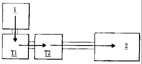
Fig. 1 shows an ion trapping system according to an
embodiment comprising two ion traps arranged in series
and having different low mass cut-offs so that ions not
trapped in the first ion trap are trapped in the second
ion trap;
Fig. 2 shows a Mathieu Stability Diagram for a
quadrupole ion trap;
Fig. 3 shows an ion trapping system according to
the preferred embodiment which includes a further ion
trap for assisting in coupling the ion trapping system
to an orthogonal acceleration Time of Flight mass
analyser;
Fig. 4 shows a table illustrating the various
stages which may be performed in mass analysing ions
having mass to charge ratios within the range 100-3000
mass to charge ratio units according to an embodiment of
the present invention;
Fig. 5 shows a less preferred embodiment wherein a
single mass-selective ion trap is coupled to an
orthogonal acceleration Time of Flight mass analyser via
a further ion trap;
Fig. 6 shows an ion trapping system according to
the preferred embodiment for performing MS/MS
experiments wherein additional ion storage traps for
storing parent ions are provided; and
Fig. 7 shows an ion trap ion source according to an
embodiment wherein a microtitre sample plate or other
target plate forms part of one end-cap of an ion trap.
A preferred embodiment of the present invention
will now be described with reference to Fig. 1. Fig. 1
CA 02436880 2003-08-08
- 24 -
shows an embodiment wherein two ion traps Tl,T2, for
example 3D (Paul) quadrupole ion traps, are arranged in
series to provide an ion trapping system having an
improved overall mass range. The ion trapping system is
arranged to receive ions from an ion source 1. However,
the ions may not necessarily be generated externally to
the first ion trap T1 and according to another
embodiment described in more detail later, ions may be
generated or formed within the first ion trap T1.
If ions are generated externally to the first ion
trap T1 then they are preferably transferred from the
ion source 1 into the first ion trap T1 using
inhomogeneous RF confining fields. For example, an RF
ion guide may be provided and an axial DC electric field
gradient and/or travelling DC voltages or voltage
waveforms (i.e. wherein axial trapping regions are
translated along the length of an ion guide) may be
applied to the RF ion guide in order to urge ions into
the first ion trap T1. Ions may also be transferred
from one ion trap to the other in a similar manner.
Ions may less preferably be transferred into the
first ion trap T1 or between ion traps using DC focusing
lenses or an ion guide employing a central guide wire
with a radially DC or RF containing field with or
without collision gas.
According to another embodiment ions may be
introduced axially or radially from one or more
continuous or pulsed ion sources 1 into the first T1
and/or second T2 ion traps. According to a yet further
embodiment ions from a continuous ion source may be
gated and temporarily stored in a transfer region prior
to being transferred to the first ion trap Tl.
CA 02436880 2003-08-08
- 25 -
The RF voltage supply for each ion trap T1,T2 may
be derived from a single RF generator using different
resistors to generate different amplitudes for each ion
trap Tl, T2 .
Ions having certain mass to charge ratios are
stable in a 3D quadrupole ion trap under operating
conditions which may be summarised in the form of a
Mathieu stability diagram as shown in Fig. 2 and
expressed in terms of the Mathieu coordinates aZ and qZ.
The shaded region of Fig. 2 represents ions that are
both radially and axially stable. The Mathieu
coordinates aZ and qZ
4 V,.~
m (~'"~~)~
- 8U,n
a = _ _.-
- lit s
(lo(o)
where Vrf is the amplitude (0 to peak) of the RF voltage
applied to the central ring electrode (or between the
ring electrode and the end-cap electrodes), ro is the
inscribed radius of the central ring electrode, c~ is the
angular frequency of the applied RF voltage, Ud~ is the
DC voltage applied between the ring electrode and the
end-cap electrodes and m/z is the mass to charge of an
ion within the 3D quadrupole ion trap.
It is known that 3D (Paul) quadrupole ion traps do
not store ions below a certain mass to charge ratio
known as the Low Mass Cut Off ("LMCO"). If the central
ring electrode is maintained at the same DC voltage as
CA 02436880 2003-08-08
- 26 -
the end-cap electrodes (i.e. if Ud~ is set at zero volts
and hence a2=0) then there is a maximum qZ value at which
point ions become axially unstable. This maximum qZ
value is qZ max = 0.908. At this setting of qZ the LMCO
may be calculated as follows:
4G;~
GMC'() _ .-
.,..,. ~ ~~o « ~
As will be appreciated from considering the above
equation, the LMCO may be lowered either by reducing Vrt
or by increasing ro or c.~ . Conversely, increasing Vrf has
the effect of increasing the LMCO.
According to the preferred embodiment in order to
overcome the mass range limitation inherent with a
quadrupole ion trap, two (or more) ion traps T1,T2, for
example 3D quadrupole ion traps, are provided in series
with a first ion trap T1 preferably arranged to receive
ions from an ion source 1. Some ions of interest having
mass to charge ratios below the LMCO of the first ion
trap T1 will become axially unstable within the first
ion trap T1. These ions will be axially ejected from
the first ion trap T1 but the ions of interest are
preferably not lost since they will become trapped in
the second ion trap T2 which is preferably downstream of
the first ion trap T1. The second ion trap T2 is
preferably configured to have a lower LMCO than the
first ion trap T1. Ions having mass to charge ratios
lower than the LMCO of the second ion trap T2 are either
not ions of interest or alternatively further additional
ion traps (not shown) with progressively decreasing
LMCOs may additionally be provided in series with the
first and second ion traps T1,T2 to trap these ions and
CA 02436880 2003-08-08
- 27 -
to further increase the mass range of the overall ion
trapping system.
Ions that have mass to charge ratios below the LMCO
of the first ion trap T1 are preferably transferred in
one axial direction by the application of a small DC (or
AC) field applied across the end-caps of the first ion
trap T1. Ions which have a mass to charge ratio below
the LMCO of the first ion trap T1 are preferably trapped
in the second ion trap T2 downstream of the first ion
trap Tl and which has a LMCO lower than the LMCO of the
first ion trap T1. The ions trapped and analysed may be
either positively or negatively charged.
In the embodiment shown in Fig. 1 an ion detector 2
is provided downstream of the first and second ion traps
T1,T2. According to further (unillustrated) embodiments
three, four, five, six, seven, eight, nine, ten or more
than ten ion traps may be provided in series in order to
provide an ion trapping system having a yet further
improved overall mass range. As will be appreciated, in
such embodiments the ion traps may have progressively
lower LMCO's.
A particularly preferred feature of the preferred
embodiment is that the amplitude of the AC or RF voltage
Vrf applied to e.g. the ring electrode (or less
preferably between the ring electrode and the end-cap
electrodes) of the first ion trap Tl may be
substantially higher than the voltage which might
otherwise be conventionally applied to a quadrupole ion
trap in a comparable situation. Although increasing the
amplitude of the AC or RF voltage applied to the
electrode of the first ion trap T1 has the effect of
increasing the LMCO of the first ion trap T1, ions of
interest having mass to charge ratios below the LMCO of
CA 02436880 2003-08-08
- 28 -
the first ion trap T1 will not be lost as they will be
trapped in the second ion trap T2 downstream of the
first ion trap T1.
As will be seen from the following equation for the
axial pseudo-potential well depth DZ, increasing the
amplitude Vrf of the AC or RF voltage applied to the ring
electrode of first ion trap Tl has the beneficial effect
of increasing the axial pseudo-potential well depth
within the first ion trap T1. Accordingly, ions having
either higher mass to charge ratio values and/or ions
having greater kinetic energies will preferably be
trapped more effectively within the first ion trap T1.
Ions having greater kinetic energies will be trapped
more effectively within the first ion trap T1 since ions
must (to a first approximation) have a greater kinetic
energy than the pseudo-potential axial well depth in
order to escape from being trapped within the ion trap.
The pseudo-potential axial well depth is given by:
I ,,.r _
/)_ -
- ~ Ill ,
It is clear from the above equation that increasing
the amplitude of the applied AC or RF voltage Vrf has the
effect of increasing the axial pseudo-potential well
depth. Similarly, the axial well depth may be increased
by reducing the frequency of applied AC or RF voltage or
by reducing the radius ro of the central ring electrode.
Fig. 3 shows a particularly preferred embodiment
for performing MS experiments wherein an ion trapping
system comprising two ion traps T1,T2 is coupled to an
orthogonal acceleration Time of Flight mass analyser via
CA 02436880 2003-08-08
- 29 -
a further ion trap T0. The further ion trap TO may
comprise a 3D quadrupole ion trap but according to other
embodiments may comprise other forms of ion traps.
In order to efficiently transfer all the parent
ions stored in the first and second ion traps T1,T2 into
an orthogonal acceleration Time of Flight mass analyser
it is desirable to limit the mass range of ions
transferred to the Time of Flight mass analyser at any
one point in time so that the ions received by the Time
of Flight mass analyser in any one pulse of ions have a
limited range of mass to charge ratios. As will be
explained in more detail below, it is desirable to limit
the range of mass to charge ratios of ions received into
the extraction region 3 of a Time of Flight mass
analyser so that all the ions received by the mass
analyser are still present in the extraction region 3 at
the point in time when an electrostatic pulse is applied
to electrodes in the extraction region 3 in order to
pulse ions out of the extraction region 3 and into the
drift or flight region of the Time of Flight mass
analyser. If the ions pulsed into a Time of Flight mass
analyser have a large range of mass to charge ratios
then since the ions will in effect have passed through a
short drift or flight region in order to reach the
extraction region 3 then the ions will have become
slightly temporally dispersed according to their mass to
charge ratio. Accordingly, some ions will have passed
beyond the end of the extraction region 3 whilst other
ions will not have yet reached the extraction region 3
when ions are pulsed out of the extraction region and
into the drift or flight region of the Time of Flight
mass analyser. Accordingly, if ions having a relatively
large range of mass to charge ratios are pulsed into a
CA 02436880 2003-08-08
- 30 -
Time of Flight mass analyser then the duty cycle will be
reduced since a proportion of those ions will not be
orthogonally accelerated into the drift or flight region
of the Time of Flight mass analyser. The further ion
trap TO is provided to address this problem and will be
described in more detail below.
Ions are also preferably ejected and transferred
out of the first and second ion traps T1,T2 by mass-
selective instability. The process involves ramping up
the AC or RF voltage amplitude applied to the ring
electrodes and pushing ions having low mass to charge
ratios above a q2 value of 0.908. An alternative method
for mass selection is resonant excitation wherein either
a specific or a broadband of secular frequencies are
applied to axially eject or retain groups of ions having
particular mass to charge ratios. A supplementary RF
dipole electric field may be applied across the end-cap
electrodes and may be used in conjunction with a mass-
selective instability scan.
Ions which have been mass-selectively ejected from
the first and second ion traps T1,T2 are relatively
energetic and these ions are then preferably trapped and
collisionally cooled (i.e. thermalised) within the
further ion trap T0. Once the ions have been
collisionally cooled the RF voltage applied to the
further ion trap TO is then preferably switched OFF or
otherwise reduced substantially. The collisional
cooling gas pressure may also be reduced substantially
at the same time. For example, the pressure within the
further ion trap TO may be allowed to reduce from e.g.
10-3 mbar to < 10-4 mbar. If the further ion trap TO is
a quadrupole ion trap then an axial DC field may then be
applied across one or more of the end-cap electrodes
CA 02436880 2003-08-08
- 31 -
and/or ring electrodes of the further ion trap TO so
that ions are pulsed out of the further ion trap T0.
The axial DC field is applied to accelerate and transfer
ions from the further ion trap TO into the extraction
region 3, for example, of the orthogonal acceleration
Time of Flight mass analyser.
The spread of ion energies in the axial direction
of the ions entering the extraction region 3 of the Time
of Flight mass analyser will depend upon their thermal
energy after collisional cooling with, for example,
helium gas at room temperature in the further ion trap
T0. Ions which have been thermalised will have an
energy of approximately 0.05 eV. After application of
an electrostatic extraction pulse of approximately 100V
across the end-cap electrodes of the further ion trap TO
ions will assume differential kinetic energies depending
upon their location within the further ion trap TO when
the extraction pulse was applied. Ions pulsed out of
the further ion trap TO may therefore have a mean
kinetic energy of e.g. 50 eV and an energy spread of ~ 5
eV. Without collisionally cooling the ions in the
further ion trap TO the ion energy spread of the ions
ejected from the first and second ion traps would be
significantly higher and may have an adverse effect upon
a Time of Flight mass analyser attempting to mass
analyse the ions. Reducing the energy spread to a few
eV ensures that the Time of Flight mass analyser is not
adversely affected.
After the ions reach the extraction region 3 of the
orthogonal acceleration Time of Flight mass analyser, an
orthogonal electrostatic pulse is then preferably
applied to the extraction region 3 so as to accelerate
ions into the drift or flight region of the Time of
CA 02436880 2003-08-08
- 32 -
Flight mass analyser. The Time of Flight mass analyser
may comprise a reflectron. The above method of
collisionally cooling ions with the further ion trap TO
and transferring ions from the further ion trap TO to
the extraction region 3 in a pulsed non mass-selective
manner has the important advantage of minimising the
energy spread of ions exiting from the further ion trap
T0. This has the effect of optimising the sensitivity
and resolution of the orthogonal acceleration Time of
Flight mass analyser. Scanning a quadrupole ion trap
such as the first and/or second ion traps Tl,T2 in order
to mass-selectively eject ions causes those ions to be
driven or excited into a state of instability.
Therefore, by avoiding mass-selectively scanning the
ions out of the further ion trap TO the ions once
collisionally cooled in the further ion trap TO remain
in a relatively unenergetic state which is advantageous
when the ions are transmitted to a Time of Flight mass
analyser. Another important advantage of the embodiment
shown in Fig. 3 is that ions can be mass-selectively
ejected from the first and/or second ion traps T1,T2
into the further ion trap TO in such a way that the ions
in the further ion trap TO which are then onwardly
transmitted to the Time of Flight mass analyser have a
limited range of mass to charge ratios which is
desirable in order to optimise the duty cycle of the
Time of Flight mass analyser.
In spite of the above, according to a less
preferred embodiment the AC or RF voltage applied to the
further ion trap TO may nonetheless still be maintained
and ions could, less preferably, be axially ejected from
the further ion trap TO into the orthogonal acceleration
Time of Flight mass analyser either by resonant ejection
CA 02436880 2003-08-08
- 33 -
(wherein an oscillating AC voltage is applied between
the end-cap electrodes) or by mass selective ejection
(wherein the RF voltage is raised, or the RF frequency
is lowered, or a DC voltage is applied between any or
all of the ring electrodes and the end-cap electrodes).
Mass-selectively ejecting ions from the further ion trap
TO is less preferred since the ion energy spread of the
ions is increased which is generally undesirable when
using Time of Flight mass analyser. However, although
the increased energy spread may be disadvantageous, the
further ion trap TO may emit ions having a limited range
of mass to charge ratios which will improve the duty
cycle of the Time of Flight mass analyser. Such an
arrangement may offer some advantages over conventional
arrangements but is less preferred compared to using DC
extraction techniques for the reasons given above.
At the point in time when the extraction pulse of
the orthogonal acceleration Time of Flight mass analyser
is energised it is desirable that the lowest mass to
charge ratio ions received from the further ion trap TO
will not quite have reached the end of the extraction
region 3 whilst the highest mass to charge ratio ions
will have just entered the extraction region 3.
Engineering constraints and other considerations
effectively limit the physical position or length of the
extraction region 3 and this effectively limits the mass
range of ions which can be orthogonally accelerated with
a near 100% duty cycle in any one pulse. In order to
address this problem the AC or RF and/or DC voltages of
the penultimate ion trap (i.e. the second ion trap T2 in
the case of the embodiment shown in Fig. 3) may
preferably be controlled so as to axially transfer only
ions having mass to charge ratios within a sub-range or
CA 02436880 2003-08-08
- 34 -
fraction of the overall range of mass to charge ratios
of ions stored within the (second) ion trap T2 into the
last ion trap (i.e. further ion trap TO). Ions are
therefore preferably mass-selectively ejected from the
(second) ion trap T2 into the further ion trap TO so
that all the ions which are then subsequently pulsed out
of the further ion trap TO are substantially
subsequently orthogonally accelerated within the
extraction region 3 of the Time of Flight mass analyser.
After a group of ions has been mass analysed by the
orthogonal acceleration Time of Flight mass analyser,
another sub-range or fraction of the ions stored in the
second ion trap T2 may then be transferred into the
further ion trap TO to be collisionally cooled prior to
being passed to the Time of Flight mass analyser. A
sub-range or fraction of ions stored in the first ion
trap Tl may also be transferred to the second ion trap
T2 for onward transmission to the further ion trap TO or
for the process of mass-selectively ejecting some ions
from the second ion trap T2 to be repeated. This
process may be repeated a number of times until all the
ions in the first and second ion traps T1,T2 have been
transferred to the Time of Flight mass analyser via the
further ion trap TO in a number of stages. The further
ion trap TO may be considered to constitute a
collisional cooling stage which reduces the energy
spread of ions enabling the Time of Flight mass analyser
to operate more effectively.
The embodiment shown in Fig. 3 can therefore be
considered to use at least two ion traps T1,T2 to
increase the overall mass range of ions stored in ion
trapping system T1,T2 by arranging for the LMCO of the
second ion trap T2 to be lower than the LMCO of the
CA 02436880 2003-08-08
- 35 -
first ion trap T1. The embodiment shown in Fig. 3 also
advantageously optimises the mass to charge ratio range
of ions transmitted to the orthogonal acceleration Time
of Flight mass analyser by using a further ion trap T0.
The further ion trap TO also collisionally cools ions
within the further ion trap TO thereby reducing the ion
energy spread.
An example of a MS mode of operation will now be
described in more detail with reference to Fig. 3. The
ion source 1 may according to one embodiment comprise a
MALDI ion source which may, for example, typically
produce ions having mass to charge ratios in the range
30-3000. Ions of particular interest may have mass to
charge ratios in the range 100-3000 i.e. ions having
mass to charge ratios in the range 30-100 may not be of
particular interest and may be lost. The ions from the
ion source 1 are preferably transferred into the first
ion trap T1 and the ions are preferably collisionally
cooled within the first ion trap T1.
The LMCO of the first ion trap Tl may be set, for
example, at m/z 300 so that ions having relatively high
mass to charge ratios e.g. up to m/z 3000 are more
efficiently trapped within the first ion trap T1 than
they would otherwise be since a higher AC or RF
amplitude Vrf can be applied to the ring electrodes) (or
less preferably between the ring electrodes) and the
end-cap electrodes) of the first ion trap T1.
Preferably, the end-cap electrodes) of the first ion
trap T1 are grounded. The relatively higher AC or RF
voltage amplitude applied to the ring electrodes) of
the first ion trap T1 results in a greater axial pseudo-
potential well depth being provided within the first ion
CA 02436880 2003-08-08
- 36 -
trap T1 which improves the trapping of high mass to
charge ratio ions and energetic ions.
A slight DC bias may be applied across the end-cap
electrodes of the first ion trap T1 so that ions having
mass to charge ratios below the LMCO of the first ion
trap T1 (i.e. m/z < 300) and which are axially unstable
within the first ion trap T1 will be axially ejected
from the first ion trap T1 in the direction of the
second ion trap T2. The low mass to charge ratio ions
ejected from the first ion trap T1 are transferred
whilst preferably undergoing further collision cooling
and become trapped in the second ion trap T2 which is
preferably downstream of the first ion trap T1.
The LMCO for the second ion trap T2 is preferably
set lower than the LMCO of the first ion trap T1. For
example, the LMCO of the second ion trap T2 may be set
at m/z 100 (compared with m/z 300 for the first ion trap
T1). Ions trapped in the first ion trap T1 will
therefore have mass to charge ratios within the range
m/z 300-3000 and ions trapped within the second ion trap
T2 will have mass to charge ratios within the range m/z
100-300.
If the distance from the origin of the further ion
trap TO to the start of the orthogonal extraction region
3 of the Time of Flight mass analyser is 100 mm and the
distance from the origin of the further ion trap TO to
the end of the orthogonal extraction region 3 is 141.4
mm then for efficient ion transfer the maximum mass to
charge ratio divided by the minimum mass to charge ratio
of ions in any packet of ions received by the Time of
Flight mass analyser should be less than:
CA 02436880 2003-08-08
- 37 -
141.4 Z = 2.00
100
According to one embodiment therefore, ions are
preferably transferred from the second ion trap T2 to
the further ion trap TO in two (or more) separate
stages. Ions having mass to charge ratios in the range
m/z 100-200 may be transferred, for example, from the
second ion trap T2 in a first stage and ions having mass
to charge ratios in the range m/z 200-300 may be
transferred out of the second ion trap T2 in a second
stage. After these two stages the second ion trap T2
will now be effectively empty of ions. Ions from the
first ion trap T1 may then be transferred via the second
ion trap T2 and via the further ion trap TO to the
extraction region 3 of the Time of Flight mass analyser.
For example, ions having mass to charge ratios in the
range m/z 300-600 may be transferred out of the first
ion trap T1 in one stage followed in the next stage by
ions having mass to charge ratios in the range m/z 600-
1200, followed by ions having mass to charge ratios in
the range m/z 1200-2400. followed finally, in a last
stage, by ions having mass to charge ratios in the range
m/z 2400-3000. As will be appreciated, in each stage of
transferring ions the ratio of the maximum mass to
charge ratio to the minimum mass to charge ratio
preferably does not exceed 2. According to this
particular example ions are transferred to the Time of
Flight mass analyser in six discrete stages and a total
of six orthogonal extraction pulses are required in
order to mass analyse ions effectively across the entire
desired m/z range of 100-3000. As will be appreciated
since the first and second ion traps T1,T2 are
CA 02436880 2003-08-08
38
preferably operated in mass-selective (i.e. scanning)
modes of operation the order in which ions are
transferred may be varied so long as preferably the ions
received in the extraction region 3 of the Time of
Flight mass analyser in any one pulse have a limited
range of mass to charge ratios. According to an
embodiment the ratio of the maximum mass to charge ratio
to the minimum mass to charge ratio is less than or
equal to 4, further preferably less than or equal to 3,
further preferably less than or equal to 2.
In order to pulse ions out of the further ion trap
TO cooling gas is preferably removed or allowed to
disperse from the further ion trap TO so that the
pressure within the further ion trap TO drops to e.g. <
10-4 mbar. The AC or RF voltage applied to the further
ion trap TO is also preferably switched OFF, and one or
more DC extraction pulses are preferably applied across
the end-cap electrodes of the further ion trap TO in
order to accelerate ions out of the further ion trap TO
and into the extraction region 3 of the orthogonal
acceleration Time of Flight mass analyser.
Fig. 4 illustrates in more detail how the
arrangement of ion traps shown in Fig. 3 may be operated
in order to perform a typical MS experiment. The first
ion trap T1, the second ion trap T2 and the further ion
trap TO are preferably similar 3D (Paul) quadrupole ion
traps.. The frequency of the RF voltage applied to all
three ion traps T1,T2,T0 is preferably 0.8 MHz (5.0
Rad/us) and the radius of the central ring electrode ro
of each ion trap Tl,T2,T0 is preferably 0.707 cm. Ud~ is
preferably OV for all the ion traps T1,T2,T0 and the ion
traps T1,T2,T0 are preferably supplied with helium gas
at a pressure of, for example, 0.001 mbar. As will be
CA 02436880 2003-08-08
- 39 -
appreciated from the description below, where the RF low
and high voltages are shown in Fig. 4 as being the same
in a stage of operation then the ion trap is not scanned
during that particular stage.
In a first stage S1 ions having mass to charge
ratios in the range 300-3000 are stored in the first ion
trap T1 wherein an RF voltage of 913.8 V is applied to
the ring electrodes) of the first ion trap Tl. Ions
having mass to charge ratios in the range 100-300 are
stored in the second ion trap T2 wherein an RF voltage
of 304.6 V is applied to the ring electrodes) of the
second ion trap T2. The further ion trap TO is
preferably initially empty of ions.
In the next stage S2 the amplitude of the RF
voltage applied to the ring electrodes) of the second
ion trap T2 is scanned from 304.6 V to 609.2 V with the
effect that ions having mass to charge ratios in the
range 100-200 are ejected from the second ion trap T2
and are transferred to the further ion trap TO where
they are collisionally cooled.
In the next stage S3, the cooling gas within the
further ion trap TO is allowed to disperse and the
pressure within the further ion trap TO is allowed to
effectively drop by switching OFF a valve pump supplying
cooling gas to the further ion trap T0. The 304.6 V RF
voltage supplied to the ring electrodes) of the further
ion trap TO is turned OFF and ions are pulsed out of the
further ion trap TO into the orthogonal acceleration
region 3 of the Time of Flight mass analyser. Cooling
gas is then re-introduced into the further ion trap TO
and a RF voltage of 609.2V is applied to the ring
electrodes) of the further ion trap TO so that the
further ion trap TO is optimised to receive at the next
CA 02436880 2003-08-08
- 40 -
stage ions having mass to charge ratios above 200 mass
to charge ratio units.
In a fourth stage S4, the RF voltage applied to the
second ion trap is scanned from 609.2 V to 913.8 V which
has the effect of ejecting the remaining ions having
mass to charge ratios within the range 200-300 from the
second ion trap T2 into the further ion trap TO where
they are collisionally cooled.
In a fifth stage S5, the cooling gas within the
further ion trap TO is allowed to disperse and the
pressure within the further ion trap TO is allowed to
effectively drop by switching OFF a valve pump supplying
cooling gas to the further ion trap T0. The 609.2 V RF
voltage supplied to the ring electrodes) of the further
ion trap TO is turned OFF and ions are pulsed out of the
further ion trap TO into the orthogonal acceleration
region 3 of the Time of Flight mass analyser. Cooling
gas is then re-introduced into the further ion trap TO
and a RF voltage of 913.8V is applied to the ring
electrodes) of the further ion trap TO so that the
further ion trap TO is optimised to receive in a
subsequent stage ions having mass to charge ratios above
300 mass to charge ratio units.
In a sixth stage S6, the RF voltage supplied to the
first ion trap Tl is scanned from 913.8 V to 1827.6 V
which has the effect of ejecting ions having mass to
charge ratios within the range 300-600 mass to charge
ratio units from the first ion trap T1 into the second
ion trap T2.
In the next seventh stage S7 the amplitude of the
RF voltage applied to the ring electrodes) of the
second ion trap T2 is scanned from 913.8 V to 1827.6 V
with the effect that ions having mass to charge ratios
CA 02436880 2003-08-08
- 41 -
in the range 300-600 are ejected from the second ion
trap T2 into the further ion trap TO where they are
collisionally cooled.
In an eighth stage S8, the cooling gas within the
further ion trap TO is allowed to disperse and the
pressure within the further ion trap TO is allowed to
effectively drop by switching OFF a valve pump supplying
cooling gas to the further ion trap T0. The 913.8 V RF
voltage supplied to the ring electrodes) of the further
ion trap TO is turned OFF and ions are pulsed out of the
further ion trap TO into the orthogonal acceleration
region 3 of the Time of Flight mass analyser. Cooling
gas is then re-introduced into the further ion trap TO
and a RF voltage of 1827.6V is applied to the ring
electrodes) of the further ion trap TO so that the
further ion trap TO is optimised to receive at a
subsequent stage ions having mass to charge ratios above
600 mass to charge ratio units.
In a ninth stage S9, the RF voltage supplied to the
first ion trap Tl is scanned from 1827.6 V to 3655.2 V
which has the effect of ejecting ions having mass to
charge ratios within the range 600-1200 mass to charge
ratio units from the first ion trap T1 into the second
ion trap T2.
In the next tenth stage S10 the amplitude of the RF
voltage applied to the ring electrodes) of the second
ion trap T2 is scanned from 1827.6 V to 3655.2 V with
the effect that ions having mass to charge ratios in the
range 600-1200 are ejected from the second ion trap T2
into the further ion trap TO where they are
collisionally cooled.
In an eleventh stage 511, the cooling gas within
the further ion trap TO is allowed to disperse and the
CA 02436880 2003-08-08
- 42 -
pressure within the further ion trap TO is allowed to
effectively drop by switching OFF a valve pump supplying
cooling gas to the further ion trap T0. The 1827.6 V RF
voltage supplied to the ring electrodes) of the further
ion trap TO is turned OFF and ions are pulsed out of the
further ion trap TO into the orthogonal acceleration
region 3 of the Time of Flight mass analyser. Cooling
gas is then re-introduced into the further ion trap TO
and a RF voltage of 3655.2V is applied to the ring
electrodes) of the further ion trap TO so that the
further ion trap is optimised to receive at a subsequent
stage ions having mass to charge ratios above 1200 mass
to charge ratio units.
In a twelfth stage 512, the RF voltage supplied to
the first ion trap Tl is scanned from 3655.2 V to 7310.5
V which has the effect of ejecting ions having mass to
charge ratios within the range 1200-2400 mass to charge
ratio units from the first ion trap T1 into the second
ion trap T2.
In the next thirteenth stage S13 the amplitude of
the RF voltage applied to the ring electrodes) of the
second ion trap T2 is scanned from 3655.2 V to 7310.5 V
with the effect that ions having mass to charge ratios
in the range 1200-2400 are ejected from the second ion
trap T2 into the further ion trap TO where they are
collisionally cooled.
In an fourteenth stage 514, the cooling gas within
the further ion trap TO is allowed to disperse and the
pressure within the further ion trap TO is allowed to
effectively drop by switching OFF a valve pump supplying
cooling gas to the further ion trap T0. The 3655.2 V RF
voltage supplied to the ring electrodes) of the further
ion trap TO is turned OFF and ions are pulsed out of the
CA 02436880 2003-08-08
- 43 -
further ion trap TO into the orthogonal acceleration
region 3 of the Time of Flight mass analyser. Cooling
gas is then re-introduced into the further ion trap TO
and a RF voltage of 7310.5V is applied to the ring
electrodes) of the further ion trap TO so that the
further ion trap TO is optimised to receive in a
subsequent stage ions having mass to charge ratios above
2400 mass to charge ratio units.
In a fifteenth stage 515, the RF voltage supplied
to the first ion trap T1 is scanned from 7310.5 V to
9138.1 V which has the effect of ejecting ions having
mass to charge ratios within the range 2400-3000 mass to
charge ratio units from the first ion trap Tl into the
second ion trap T2, thereby emptying the first ion trap
T1 of ions.
In the next sixteenth stage S16 the amplitude of
the RF voltage applied to the ring electrodes) of the
second ion trap T2 is scanned from 7310.5 V to 9138.1 V
with the effect that ions having mass to charge ratios
in the range 2400-3000 are ejected from the second ion
trap T2 into the further ion trap TO thereby emptying
the second ion trap T2. The ions are preferably
collisionally cooled within the further ion trap T0.
In a final seventeenth stage 517, the cooling gas
within the further ion trap TO is allowed to disperse
and the pressure within the further ion trap TO is
allowed to effectively drop by switching OFF a valve
pump supplying cooling gas to the further ion trap T0.
The 7310.5 V RF voltage supplied to the ring
electrodes) of the further ion trap TO is turned OFF
and ions are pulsed out of the further ion trap TO into
the orthogonal acceleration region 3 of the Time of
Flight mass analyser. Cooling gas may then be re-
CA 02436880 2003-08-08
- 44 -
introduced into the further ion trap TO and a RF voltage
applied to the ring electrodes) of the further ion trap
TO ready for the next cycle.
In order to pulse ions out of the further ion trap
TO and into the extraction region 3 of a Time of Flight
mass analyser a DC voltage preferably in the range 10-
500 V may be applied across the end-cap electrodes of
the further ion trap TO in order to accelerate ions out
of the further ion trap T0. The DC voltage may be
applied, for example, for a minimum of 1 us and
according to other embodiments the DC extraction voltage
may be applied for at least 5, 10, 15, 20, 25, 30, 35,
40, 45, 50, 55, 60, 65, 70, 75, 80, 85, 90, 95 or 100
us.
In the example described above in relation to Fig.
4, ions are scanned out of either the first ion trap T1
or the second ion trap T2 ten times per cycle. Each
scan of the RF voltage applied to the ion trap
preferably takes approximately 50 ms. The collisional
cooling and pulsed extraction stage which occurs in the
further ion trap TO occurs six times per cycle in the
example described in relation to Fig. 4. The ions are
preferably collisionally cooled in the further ion trap
TO for approximately at least 30 ms. Once ions have
been collisionally cooled in the further ion trap TO
then the RF voltage to the further ion trap TO is
preferably switched OFF, ions are pulsed out of the
further ion trap T0, the RF voltage is re-applied and
gas is re-introduced into the further ion trap T0. This
process preferably takes of the order of 50 ms. The
overall cycle time is preferably around 1.1 seconds.
Not included in the calculation of the cycle time is the
time taken to ionise the ions and transfer them into the
CA 02436880 2003-08-08
- 45 -
first ion trap T1. The ion source is preferably pulsed
and may be pulsed for example 10-100 times per second.
With reference back to Fig. 3 a MS/MS mode of
operation may also be performed wherein the first ion
trap T1 is controlled to selectively retain parent ions
having a particular mass to charge ratio of interest
whilst all other parent ions are preferably ejected out
of the first ion trap T1.
The parent ions retained within the first ion trap
T1 are then preferably collisionally fragmented within
the first ion trap T1 by e.g. setting the qZ value of
the first ion trap Tl to about 0.3 which causes the
parent ions to be sufficiently energetic that they
fragment upon colliding with the background gas within
the first ion trap T1. Preferably, resonant excitation
is applied to specific parent ions and this causes
repetitive higher energy collisions with e.g. helium gas
within the first ion trap T1 so that the parent ions
gain sufficient internal energy that Collisional Induced
Dissociation (CID) occurs. Fragment ions having qZ >
0.908 will be axially unstable within the first ion trap
Tl and will exit the first ion trap T1 along the z-axis
and will preferably become trapped within the second ion
trap T2. Fragment ions may therefore be trapped in both
the first and second ion traps T1,T2 and the fragment
ions may be efficiently transferred via the second ion
trap T2 and via the further ion trap TO to the mass
analyser in a similar manner to that described above in
relation to the MS mode of operation.
According to a less preferred embodiment shown in
Fig. 5 a single e.g. mass-selective ion trap Tl may be
coupled to an orthogonal acceleration Time of Flight
mass analyser via a further ion trap T0. Such an
CA 02436880 2003-08-08
- 46 -
arrangement allows a limited mass range of ions to be
collisionally cooled and then transferred to the Time of
Flight mass analyser so that the ions received by the
Time of Flight mass analyser in any one pulse are all
substantially orthogonally accelerated into the drift
region. The embodiment shown in Fig. 5 does not however
afford the benefit of an improved mass range trapping
system which requires two or more ion traps T1,T2 having
different LMCOs.
Although the embodiments shown in Figs. 3 and 5 are
capable of performing MS/MS experiments, parent ions
other than those initially trapped in the first ion trap
T1 may be effectively lost. In order to significantly
increase the sampling efficiency of the parent ions, a
further preferred embodiment shown in Fig. 6 is
contemplated wherein additional ion traps TA,TB are
provided to store parent ions ejected from the first ion
trap T1 and which are not to be the subject of immediate
MS/MS analysis. A second additional ion trap TB may
preferably be configured to have a lower LMCO than a
first additional ion trap TA so that an improved ion
trapping system for storing parent ions which are not
yet the subject of immediate mass analysis is provided.
Once a MS/MS experiment has been performed, the
next parent ions of interest may be transferred from the
first additional ion trap TA and/or the second
additional ion trap TB into the first ion trap T1
wherein the parent ions are then subject to
fragmentation.
According to an alternative embodiment all the ions
trapped within the first and second additional ion traps
TA and TB may be transferred back into the first ion
trap T1 in, for example, a non mass-selective manner and
CA 02436880 2003-08-08
- 47 -
then the next parent ions of interest may then
selectively retained within the first ion trap Tl whilst
all the other parent ions are mass-selectively ejected
out of the first ion trap T1 and back into one or more
of the additional ion traps TA, TB. Further additional
ion traps (not shown) may also be provided to improve
the trapping efficiency of parent ions awaiting further
MS/MS analysis.
Ions may, for example, be generated by a MALDI ion
source 1 and may typically have mass to charge ratios in
the range m/z 30-3000. The ions emitted from the ion
source 1 may be transferred to and collisional cooled
within the first ion trap T1, although according to
other embodiments ions may be generated within the first
ion trap Tl. A MS spectrum may have been previously
acquired and it may be desired, for example, to obtain a
MS/MS mass spectrum of parent ions having a particular
mass to charge ratio e.g. 1500. Parent ions having mass
to charge ratios other than 1500 may be ejected out of
the first ion trap Tl and passed initially into the
first additional ion trap TA. This may be achieved, for
example, by applying a swept frequency to the end-cap
electrodes of the first ion trap T1 which causes
resonant excitation (axial modulation with a
supplementary oscillating potential) of all ions except
for the desired parent ions. The RF voltage applied to
the first ion trap Tl may also be temporarily. reduced to
increase the LMCO.
According to another embodiment all the ions within
the first ion trap T1 may be transferred into the first
additional ion trap TA and then the parent ions of
interest having mass to charge ratios of 1500 may then
be transferred back from the first additional ion trap
CA 02436880 2003-08-08
- 48 -
TA into the first ion trap Tl using similar methods as
described above.
Parent ions having mass to charge ratios below the
LMCO of the first additional ion trap TA may be trapped
in a second (or yet further) additional ion trap TB
which is preferably provided in series with the first
additional ion trap TA and which preferably has, in use,
a lower LMCO than the first additional ion trap TA.
Having isolated ions having a mass to charge ratio
of 1500 in the first ion trap Tl and having preferably
stored elsewhere (i.e. in additional ion traps TA, TB)
all the other parent ions of interest, the qzfor the
first ion trap Tl may be set at 0.3 (for m/z 1500) to
cause sufficient excitation for fragmentation of the
parent ions to occur without either axial or radial
ejection. The LMCO of the first ion trap Tl may be set
to m/z 500. The LMCO for the second ion trap T2
downstream of the first ion trap T1 may be set at m/z
100 i.e. lower than the LMCO of the first ion trap T1.
A background collisional gas is preferably retained
within or is introduced into the first ion trap T1 and a
resonant excitation function is preferably applied to
the end-cap electrodes of the first ion trap Tl in order
to increase the kinetic and internal energy of the
parent ions so that they then fragment upon colliding
within gas molecules within the first ion trap T1.
Fragment ions having mass to charge ratios in the range
m/z, for example 100-1500, may be produced by such
collisional activation. Fragment ions having mass to
charge ratios below m/z 500 will become axially unstable
in the first ion trap T1 and are preferably axially
ejected from the first ion trap Tl so that they become
trapped in the second ion trap T2.
CA 02436880 2003-08-08
- 49 -
Fragment ions are now efficiently extracted from
the first and second ion traps Tl,T2 and passed to the
mass analyser in a number of discrete stages in a
similar manner to the MS mode of operation described
above in relation to Fig. 4. In a first stage, ions in
the range m/z 100-200 may be transferred from the second
ion trap T2 to the further ion trap TO where they are
collisionally cooled before being transmitted to the
Time of Flight mass analyser. In a second stage ions in
the range m/z 200-400 may be transferred from the second
ion trap T2 to the further ion trap TO where they are
collisionally cooled before being transmitted to the
Time of Flight mass analyser. In a third stage ions in
the range m/z 400-500 may be transferred from the second
ion trap T2 to the further ion trap TO where they are
collisionally cooled before being transmitted to the
Time of Flight mass analyser.
The three stages described above result in the
emptying of the second ion trap T2 of all fragment ions.
Fragment ions having mass to charge ratios in the range
m/z 500-1000 may then transferred from the first ion
trap Tl to the Time of Flight mass analyser via the
second ion trap T2 and via the further ion trap T0.
Subsequently, fragment ions having mass to charge ratios
in the range 1000-2000 mass to charge ratio units may be
transferred from the first ion trap Tl via the second
ion trap T2 and via the further ion trap TO to the Time
of Flight mass analyser.
Having acquired all the MS/MS data from one
particular parent ion other MS/MS acquisitions may then
be performed on some or preferably all of the remaining
parent ions which have been meanwhile stored in the
first and second additional ion traps TA and TB.
CA 02436880 2003-08-08
- 50 -
Advantageously, none of the parent ions are lost and
full MS/MS data may be acquired for all the parent ions
of interest.
According to a less preferred and unillustrated
embodiment, the first and second additional ion traps TA
and TB may be interspersed between the first and second
ion traps T1,T2 or may be placed downstream of the first
and/or second ion traps T1,T2.
A particularly preferred ion trapping system and
ion trap ion source will now be described with reference
to Fig. 7. In order to reduce potential transmission
losses between ion traps and in order to increase the
homogeneity of the electric field when pulsing ions into
the orthogonal acceleration Time of Flight mass
analyser, the electrodes of the various ion traps may be
constructed in the form of several cylindrical thin
rings lOA,lOB,lOC. In the embodiment shown in Fig. 7
each ion trap comprises three such thin rings. Adjacent
ion traps may furthermore be separated by common end-cap
electrodes 11 incorporating high transmission grids 12
to reduce field penetration. Alternatively, some or all
of the gridded end-cap electrodes 11 may be replaced
with circular plate electrodes having relatively small
apertures and which may, in one embodiment, form
differential pumping apertures between vacuum stages.
Ions may be generated from a sample or target plate
within or close to the first ion trap T1 by a laser 14
producing a laser beam 15. The firing of the laser 14
may be synchronised with the phase of the RF voltage
applied to the ring electrodes 10A of the first ion trap
T1 so that the ions generated on or at the sample or
target plate 13 immediately fly into and within the
first ion trap T1. The electric field applied to the
CA 02436880 2003-08-08
- 51 -
first ion trap T1 therefore preferably effectively
extracts ions at the moment they are generated so as to
preferably avoid or minimise the risk that the ions are
reflected back towards the sample or target plate 13
which might otherwise result in the ions being lost.
The angle 8 between the sample or target plate 13 and
the ionising pulsed laser beam 15 (or less preferably
electron beam) may be 90° in which case the pulsed laser
beam 15 (or electron beam) may pass through the
extraction region 3 of the orthogonal acceleration Time
of Flight mass analyser. Angles < 90° may also be used
and are shown, for example, in the particular embodiment
shown in Fig. 7. According to another embodiment a
mirror or other reflective element may be provided
between the ion trap ion source and the mass analyser.
The mirror may, for example, be orientated at 45°. A
laser beam may be directed at the mirror and then
reflected on to the target or sample plate 13. Ions
generated by the ion trap ion source may preferably be
transmitted through a small aperture provided in the
mirror or other reflective element.
According to the preferred embodiment the ring
electrodes lOA,lOB,lOC of the first, second and further
ion traps T1,T2,T0 are supplied with RF voltages having
a frequency of 800 kHz. The amplitude of the RF
voltages supplied to each of the first, second and
further ion traps T1,T2,T0 may differ. The DC voltage
applied to all the ion traps Tl,T2,T0 is preferably set
at zero. The first, second and further ion traps
T1,T2,T0 are preferably provided with helium gas and
maintained at a pressure of 10-3 mbar. Before ions are
extracted from the further ion trap TO into the
CA 02436880 2003-08-08
- 52 -
orthogonal acceleration region 3 of the Time of Flight
mass analyser, the pressure in the further ion trap TO
may be reduced to < 10-4 mbar. According to one
embodiment, when the pressure in the further ion trap TO
is reduced the pressure in the first and/or second ion
traps T1,T2 may also be reduced to a similar pressure as
that of the further ion trap T0.
In order to maintain an ion trap at a pressure such
that collisional cooling of ions occurs or collisional
activation occurs for MS/MS experiments, helium gas may
be introduced into the ion trap to raise the pressure in
the ion trap to around 10-3 mbar. The helium or other
gas may be introduced using a solenoid operated needle
valve or a pulsed supersonic valve (available, for
example, from R.M. Jordan Inc.). The pulsed supersonic
valve may be operated so as to provide 50 us pulses of
gas at a 10 Hz repetition rate. Once collision or
cooling gas has been introduced into an ion trap the gas
may be considered to remain present within the ion trap
for approximately 10 ms before it disperses or is pumped
out of the ion trap by the vacuum pump. The precise
time that the collision gas can be considered to remain
effectively present within the ion trap depends upon the
geometry of the ion trap and vacuum chamber, and the
capacity of the vacuum pumps.
In all the embodiments described above,
differential pumping systems may be employed between the
first ion trap T1 and/or the second ion trap T2, and/or
between the second ion trap T2 and the further ion trap
T0, and/or between the further ion trap TO and the mass
analyser e.g. Time of Flight mass analyser. According
to a one embodiment the further ion trap TO downstream
of the first and second ion traps T1,T2 may be provided
CA 02436880 2003-08-08
- 53 -
in a separate vacuum chamber to that of the first and
second ion traps T1,T2. Providing the further ion trap
TO in a separate vacuum stage allows the pressure of the
gas in the further ion trap TO to be more easily varied
between 10-3 mbar (for collisional cooling) and < 10-4
mbar (for pulsed extraction of ions) whilst the first
and second ion traps T1,T2 can, for example, be
constantly maintained at around e.g. 10-3 mbar.
According to a less preferred embodiment when the valve
supplying gas to the further ion trap TO is OFF, the
valves supplying gas to the first and second ion traps
Tl,T2 may also be switched OFF.
In the embodiment shown and described in relation
to Fig. 7, the mesh end-cap electrode between the second
ion trap T2 and the further ion trap TO may be replaced
by a differential pumping apertured electrode.
The embodiment shown and described with relation to
Fig. 7 wherein ions are generated directly within an ion
trap is particularly advantageous compared to
conventional arrangements wherein ions are generated
externally to an ion trap. If a pulse of ions is
accelerated with a DC field from a point outside of an
ion trap, then ions having different mass to charge
ratios will have different flight times into the ion
trap. The timing of the RF voltage applied to the ion
trap therefore has to be carefully optimised or even
switched OFF until all the desired ions are within the
ion trap, otherwise they may be reflected backwards and
lost. The acceptance and hence successful trapping of
ions in a conventional ion trap is dependent upon the
position, kinetic energy and mass to charge ratio of the
ions being pulsed towards the ion trap at the time when
the RF voltage is applied to the ion trap. Ions
CA 02436880 2003-08-08
- 54 -
generated externally to the ion trap will therefore tend
to have a significant variation in their position which
will have an adverse effect upon the acceptance of ions
into the ion trap.
In addition to the constraints imposed by the
trapping potential, geometric constraints will also
limit the acceptance of ions into a conventional ion
trap. For example, some ions of low mass to charge
ratio may have entered and passed through the exit end-
cap electrode of the ion trap by the time that an
effective RF trapping voltage is applied to the ion
trap, whilst other ions having a relatively high mass to
charge ratio may not have yet reached the ion trap by
the time that an effective RF trapping voltage is
applied to the ion trap. Conventional ion trapping
arrangements may therefore exhibit mass to charge ratio
discrimination effects. The ion trap ion source
according to the preferred embodiment preferably does
not suffer from such problems and therefore represents a
significantly improved ion trapping and ion source
system.
Although the present invention has been described
with reference to preferred embodiments, it will be
understood by those skilled in the art that various
changes in form and detail may be made without departing
from the scope of the invention as set forth in the
accompanying claims.