Note: Descriptions are shown in the official language in which they were submitted.
CA 02437046 2003-06-04
WO 02/46525 PCT/F101/01069
1
A method for manufacturing paper with a constant filler content
Technical field
The present invention relates to a method for producing paper with a
constant filler content.
The invention is applicable in the production of any type of paper that
contains a filler and a retention agent. The filler content may range from a
very low level to
a high level, for example from one or a few percent to up to 30 0o, of the
total weight of the
paper. With respect to weight, the retention agent content is much lower than
the filler
content, normally only a fraction thereof, and generally has a given
relationship with
respect to the filler content.
Paper is mainly comprised of pulp fibres. Pulp may be produced
mechanically, chemimechanically and chemically. Lignocellulose material,
including
softwoods and hardwoods, is used as the starting material in the production of
pulp. A
typical pulp.furnish is comprised of different pulp fibres in mixture. The
pulps may. be
unbleached, semi-bleached and fully bleached, this latter pulp being the
dominating pulp.
Recycled fibres may constitute a base in the paper, either completely or
partially. The pulp
may, at times, include an admixture of synthetic fibres. The paper may include
one or more
other ingredients in the form of paper chemicals. Examples of common such
additives are
starch, hydrophobising agent, nyancing colours and fluorescent whitening
agent. Some
papers are subjected to after treatment. Examples of after treatment are
surface sizing,
coating, and calendering.
CA 02437046 2003-06-04
WO 02/46525 PCT/F101/01069
2
Examples of types of paper that can inlcude a filler are fine paper, i. e: non-
coated and coated writing paper and printing paper, security paper, liner,
label paper,
formula paper and envelope paper. Wood containing printing paper, such as
newsprint and
magazine paper may also contain a filler.
Background art
A primary reason for providing paper with a filler is to improve certain
properties of the paper. One important property in this way is the opacity of
the paper, i.e.
the non-transparency. Certain fillers improve the brightness and/or the
whiteness of the
paper. One example of such a filler is PCC (precipitated calcium carbonate),
i.e.
pr.ecipitated,calcium.carbonate. The filler. can also improve the surface
smoothness.of the
paper, resulting in improved printability. In addition, the majority of
fillers are
significantly cheaper per unit weight (kilogram or tonne) than pulp fibres.
This is
particularly the case in relation to fully bleached chemical pulps. The
admixture of filler
thus leads to a reduction in paper manufacturing costs. It is worth noting
that there is a risk
in using filler, and then particularly in large quantities, as the strength of
the paper is
impaired to a greater or lesser extent in comparison with paper that includes
no filler.
The manufacture of paper that contains a filler commences with the
production of a thick pulp suspension. This suspension can be produced in
different ways.
In the case of paper manufacture based on dry pulp in bale form, the pulp is
slushed in
water, usually white water taken from the long circulation, such as to obtain
a thick pulp
suspension. In the- case of paper manufacture based on pulp - in suspension
form that is
delivered through a conduit to the paper mill from an adjacent pulp mill, the
suspension is
usually de-watered initially, for instance from a consistency of about 2% to
about 15%, so
as to obtain a coherent pulp cake. The resultant water, free from pulp fibre,
is sent back to
the pulp mill through a conduit for renewed use as a vehicle for feeding fresh
pulp fibres to
the paper mill. The pulp cake obtained in the paper mill is broken-up and
mixed with white
water from the long circulation, so as to obtain a thick pulp suspension.
The pulp fibres in the form of a thick pulp suspension are normally
subjected to a beating process prior to their further advance in the system.
If the pulp
furnish includes, for instance, two different pulps, these pulps are usually
each beaten
separately before mixing tfie two piilp suspensibns together.
CA 02437046 2003-06-04
WO 02/46525 PCT/F101/01069
3
Relatively large quantities of paper broke are obtained in the following
paper manufacturing process. There are several causes why paper broke is
obtained. A
constantly dominating cause is because the outer edges of the advancing paper
web are cut
away as a matter of routine. Scrapping is another cause, i.e. the paper
produced does not
fulfil periodically the quality requirements placed on the paper. A third
cause can be that
the_ advancing paper web breaks-off for some reason or other. Such broke paper
is
normally passed back to the paper manufacturing chain, after having been
slushed in white
water in broke pulpers. Because this starting material in the form of paper
broke contains a
filler, the resultant thick puip* suspension will also contain a filler. The
amount of paper
broke concerned may be as high as 40%, and even higher, which is, in itself, a
problem.
However, a more difficult problem in this connection is that the amount of
paper broke
normally varies with time. This means that the filler content of the incoming
thick pulp
suspension will also vary with time.
The thick pulp suspension is diluted with white water batch-wise on its way
to the short circulation and to the head box. One or more paper chemicals can
be delivered
to the thick pulp suspension on such suspension diluting occasions.
Significant dilution of
the pulp suspension with white water takes place at the beginning of the short
circulation,
for instance in the wire pit, so as to obtain a stock that has a low solids
substance content.
Fresh filler can be delivered to the pulp suspension at several positions, for
instance to the
thick pulp suspension or to the stock 'immediately 'downstream of the wire
pit. The retention agent can be delivered to the pulp suspension at described
positions, and also
later on in the short circulation, i.e. closer to the head box.
The dominant part of the liquid phase in the pulp suspension is comprised of
constantly circulating white water. However, a permanent or temporary white
water
deficiency can be made up with fresh water.
The majority of fillers are in particle form that have a very small surface
area (e.g. a diameter smaller than 10 m) in relation to the surface area or
the size of pulp
fibres (having a length of, e.g., 3000 m and a width of, e.g., 30 m). There
is a relatively
small chance of the filler fastening in the paper web by itself or being
spontaneously taken-
up by the web. When forming the paper on the wire cloth, practically all pulp
fibres will
fasten on the cloth and form a bed or network thereon. The number of holes in
the -network
is determined by many factors, among other things by the type of paper
producing process
CA 02437046 2003-06-04
WO 02/46525 PCT/F101/01069
4
applied precisely in the paper machine and also the weight per unit area or
grarnmage of
the paper produced. There is a direct connection between an increase in
grammage and an
increase in the thickness of the pulp fibre bed. It is natural that an
increase in pulp fibres
bed thickness will result in an increase in the amount of filler that is taken
up. However,
the spontaneous adsorption or retention of filler is insufficient to provide
the desired
content of filler in the paper. It is therefore necessary to add one or more
substances or
chemicals that assist in incorporating filler in the pulp fibres bed and
therewith in the wet
paper web as it leaves the wire and, e.g. is fed into a press section of the
paper machine.
The wet paper web is transferred to an endless felt in conjunction therewith.
This substance
or chemical is designated a retention agent. The use of a retention agent
results in
comparatively more filler remaining in and accompanying the paper web, and
comparatively less filler slipping through the pulp fibres bed and down
through the wire
cloth and into the wire tray together with the drainage water or white water.
Despite the
use of a retention agent, and then even in large amounts, only a minor part of
the filler
present in the stock fed into the head box and thereafter spread on the wire
cloth will fasten
in the paper web, whereas a major part of the filler will accompany the
drainage water as it
passes through the paper web and the underlying wire cloth. This means that
the amount of
filler in the white water is still relatively high and is very large when seen
in respect of the
total amount of filler in the entire system (and then primarily in the large
volume of white
water that circulates in both the short circulation and the long circulation).
On the basis of the described circumstances, it will readily be seen that it
is
difficult to control the production of filler-containing paper in a manner
such that the final
product, i.e. the finished paper, will constantly and persistently contain the
desired filler
content or filler consistency, for instance expressed in a given percentage
value. The buyer
and the user of the paper are interested in that the quality of the paper
being always the
same, and it is important in this respect that the filler content of the paper
is always the
intended content and that this filler content is achieved constantly from
batch to batch.
In order to enable the manufacture of paper to be controlled in the above-
described respect, there have long been used measuring operations that are
carried out with
the aid of a certain type of measuring apparatus. One of these measuring
operations
involves determining the filler content of the advancing paper web, normally
at the end of
the paper machine, by means of a non-destructive measuring process, said
filler content
CA 02437046 2003-06-04
WO 02/46525 PCT/F101/01069
sometimes being referred to as the ash content. Another measuring operation
involves
determining the filler concentration of the white water either in the short
circulation or in
direct connection therewith. Alternatively, the filler concentration is
determined together
with the low quantity of pulp fibres that are already present in the white
water (total
5 concentration). The two measuring processes are normally carried out
intermittently, at
intervals ranging from, e.g., only a few seconds to, e.g., thirty seconds
between respective
measuring occasions.
In conventional control technology, both the addition of retention agent and
the addition of filler are varied in the course of making the additions. The
amount of
retention agent added is based on precisely the amount of filler measured in
the white
water, and the amount of filler added is based on the measured content of
filler in the paper
web. It has been found that this control philosophy leads to a relatively
significant
variation in the filler content of the finished paper. Because the filler
content of an
accepted paper is only allowed to vary within a narrow range, the paper that
must be
scrapped becomes much too excessive. Moreover, as a result of this control
philosophy, the
switch from one filler content to another in the paper, for instance from 15
to 19 percent or
vice versa, becomes unnecessarily extended time-wise and therewith
necessitates
unnecessarily the scrapping of much of the paper. The earlier described
problem caused by
varying amounts of filler in the incoming thick pulp suspension is not
overcome
completely by the described control philosophy. The attempt to correct a newly
measured
excessively low amount of filler in the finished paper with an increased
addition of filler to
the thick pulp suspension for instance, or to the stock, is doomed to failure
to some extent,
since the total amount of liquid, chiefly white water, in the system is, as a
whole, very
large, meaning that the amount of circulating filler is also large and also
meaning that an
instantaneous increase in the amount of filler added to the system is unable
to become
quickly effective in respect of an increase of the filler concentration in the
circulating
liquid system, which, in tum, would result in a higher quantity of filler
fastening in and
being retained by the paper web. Such a system is extremely slow to control
for these
reasons.
Finnish Patent Application 97 4327 and its corresponding International
(PCT) Patent Application WO 99/27182 describes, among other things, a method
which is
alleged to afford advantages in the form of faster and more effective control
of the paper
CA 02437046 2003-06-04
WO 02/46525 PCT/F101/01069
6
properties in the short circulation of the paper machine, in relation to known
techniques.
By paper properties is meant primarily the filler content of the paper. It
would appear that
the method concerned is based on the aforedescribed known technique, which has
been
supplemented with an incompletely explained process in which both the
continuous
addition of filler and the continuous addition of retention agent are both
based on the
measured concentration of filler in the white water and the measured filler
content or ash
content (which is the term used) of the paper.
Disclosure of the invention
Technical problem
As mentioned above, the technology used hitherto for controlling the filler
content in the manufacture of filler-containing paper results in excessively
high variations
in the filler contents obtained. The application of such technology also
results in
excessively long changeover times when changing from one filler content in the
paper to
another. Both of these deficiencies result in the scrapping of excessively
large quantities of
finished paper.
The solution
The present invention provides a solution to these problems and relates to a
method for producing paper with a constant filler content, wherein the method
comprises
a) passing a thick pulp suspension, containing water, pulp fibres, normally
filler originating from slushed paper broke and normally diverse paper
chemicals, in a
direction towards the head box of a paper machine;
b) adding water, normally white water, to the thick pulp suspension on its way
to the head box, so as to form a stock;
c) adding at least one filler to the thick pulp suspension and/or to the stock
and/or to the water addition; - .
d) adding at least one retention agent to the thick pulp suspension and/or to
the
stock and/or to the water addition;
e) spreading out a finally prepared stock over a wet apparatus, normally a
wire
section, via the head box, so as to form a wet paper web, and collecting the
water drained
from the web, designated white water, beneath the wet apparatus, and passing
said white
CA 02437046 2003-06-04
WO 02/46525 PCT/F101/01069
7
water back in the paper manufacturing process for supplying said water to
fresh thick pulp
suspension, normally divided and included in two liquid-based flows of
material,
designated the short circulation and the long circulation respectively;
f) causing the wet paper web to leave the wet apparatus and thereafter
typically pressing and drying the web in at least one stage and optionally
subsequently
treating the web and/or collecting the web on rolls or converting the web into
sheets; and
g) measuring the filler content of the paper in some position;
h) measuring the concentration of filler or the conceintration of filler plus
pulp
fibres (the total concentration) in the white water or in the stock,
preferably in a position in
the short circulation or in direct connection therewith, characterised by
adding the filler in an amount such as to buffer the system with filler to a
notmally
predetermined concentration level (control value), said level being evaluated
via
measurement process (h);
basing the continuing addition of filler exclusively on the level of the
filler concentration
measured in the white water or in the stock, and increasing the amount of
filler added when
the measured level is below the control level and reducing the amount of
filler added when
the measured level is higher than the control level at least when seen in the
long term, so
that the white water system or the buffer system will always make accessible
sufficient
filler to ensure that the paper web will take-up the intended amount of
filler; and
by basing the continuing addition of retention agent exclusively on the amount
of filler
.. ...... . : . . . . . . .
measured in the paper (g) at that moment in time, and increasing the amount of
retention
agent added when the measured amount of filler in the paper is lower than the
level that
shall be held constant, and reducing the amount of retention agent added when
the level is
higher than the level that shall be held constant, therewith resulting in fast
correction of the
filler content of the paper back to the level that shall be held constant.
With regard to the filler, any known filler can be used. It is quite possible
to
use more than one filler. The filler or fillers can be supplied in one-or more
positions.- It is
usual that one filler is used and that the total amount of filler is supplied
to the stock in a
position at the beginning of the short circulation. There is nothing to
prevent the filler
addition being divided into two or more quantities, for instance into two part-
quantities, of
which one is delivered, to the thick pulp suspension and the other to the
stock. It is optional
whether or not the additions of the two part-quantities are varied in the
course of the
CA 02437046 2003-06-04
WO 02/46525 PCT/F101/01069
S
addition, or whether the addition of one part-quantity is fixed or constant
and the addition
of the other part-quantity is varied in the course of the addition sequence.
Examples of
fillers are kaolin clay, calcium carbonate (either in the form of substances
that occur
naturally, such as limestone, marble and chalk, or newly produced substances
in the form
of PCC), titanium dioxide and talcum.
The amount of filler charged to the system per unit of time is dependent of a
number of factors, and a differentiation must be made between when filler is
added in the
start-up stage in thei manufacture of filler-containing paper and when filler
is added in a
steady state. If paper that contains a high filler content, e.g. 20%, is
produced in a steady
state, a large amount of filler is constantly taken from the liquid system or
the white water,
this filler entering and accompanying the wet paper web and because it is
necessary to
compensate the liquid system for the filler taken therefrom, at lest in the
long term, it is
necessary to add a large amount of filler in said position or positions. When
paper broke is
used as part of the starting material which is a normal case (in addition to
freshly supplied
pulp fibres), already the incoming thick pulp suspension will contain a
relatively large
amount of filler. The amount of filler present will vary with the amount of
paper broke in
the total amount of starting material and also on the amount of filler present
in the paper
broke concerned, fo~ instance 10 versus 20%. The amount of filler,that shall
be added at a
given point in time may be, and often is, partly dependent on the circumstance
just
described. There is no absolute requirement for the addition of a given amount
of filler on
each addition occasion, in order for the invention to function. This is
because of the
presence of a filler buffer in the system, and the only absolute necessity is
that the buffer
system always has available sufficient filler for the intended amount of
filler to be taken-up
in the paper web. This will be described also further on in the text.
The filler is added by initially slutrying the filler in a liquid, for
instance
white water, and then delivering the liquid together with its filler content
to the advancing
pulp fibre suspension or to the water in said possible positions, with the aid
of a regulator
or with the aid of several regulators which operates/operate in accordance
with the
described control philosophy:. The regulator or regulators may be implemented
in a
computer program ot may be constructed mechanically, or may consist of
electronic
components.
CA 02437046 2003-06-04
WO 02/46525 PCT/FI01/01069
9
Also regarding retention agent any known such agent whatsoever maybe
used. It is fully possible to limit the use to a single retention agent that
is delivered to the
system at one or more positions. It may be beneficial to use more than one
retention agent,
for instance two retention agents. These agents may be added in one and the
same position,
although there is nothing to prevent each retention agent from being added to
the system in
a respective position. Both additives may be varied in the course of making
the additions,
likewise that one addition amount can be kept constant, while the other
addition amount is
varied time after time according to the need. Distinct from the position, in
which the filler
is added to the system, it may be beneficial to add at least a part of the
requisite retention
agent relatively far forward in the short circulation, i.e. relatively close
to the head box.
Examples of retention agent are inorganic retention agents and synthetic water-
soluble
organic polymers.
Examples of inorganic retention agents are alun, bentonite clay and silica
sols and diverse silicates. Examples of synthetic water-soluble organic
polymers are
polyacryl amide, polyethylene amine, and polyamine_ The polymers may be
cationic,
anionic and nonionic polymers. The aforesaid paper chemical starch, which is
available in.
a number of different forms, is sometimes included in the retention agent
group. It can at
lest be inaintained'that the presence of starch in the system influences the
retention of
filler.
The amount of retention agent charged to the system per unit of time is also
dependent on several factors. Generally speaking, when producing paper that
has a high
filler content, more retention agent will be consumed than when producing
paper of low
filler content. One reason for this is because when producing filler-
containing paper there
occurs a spontaneous retention that is not influenced directly by the presence
of a retention
agent. It can be mentioned in this connection that the spontaneous retention
does not
slavishly follow the presence of filler in the system and, e.g., the
concentration of filler in
the white water, even though this concentration normally increases with
increasing .
concentration of filler in the white water. As before mentioned, this
spontaneous retention
is influenced by the grammage or weight per unit area of the paper produced,
and therewith
also by the thickness of the pulp fibre bed or pulp fibre network forming the
base in the
paper web. The spontaneous retention is also influenced by the type of paper
machine
used. The amount of filler which is present in the paper and which has not
been included
CA 02437046 2003-06-04
WO 02/46525 PCT/FI01/01069
via spontaneous retention is present due to and with the aid of the retention
agent supplied
to the system. Distinct from the case of filler, the system is not buffered
with retention
agent when this substance is added, but that an increase in the addition of
retention agent
results almost instantaneously in an increase in the amount of filler
incorporated in and
5 fastening in said paper or paper web. This is the reason of why, or a
contributory factor of
why, it is possible to produce persistently a filler-containing paper with a
substantially
constant filler content, as will be exemplified further on in the text. If it
is chosen to set the
amount of retention agent charged to the system per unit of time in relation
to the amount
of filler charged per unit of time, it will be found that there is not any
direct relationship
10 nor yet any relationship that varies uniformly. However, it can be said
broadly that the
weightwise addition of retention agent lies within the range of some tenths of
a percent to
about five percent of the addition of filler to the system. The mentioned
relationship is
primarily dependent on the filler content of the paper and on the type of
paper.
The retention agent addition is effer,
ted by initially.slurrying and/or.
dissolving the retention agent in liquid, for instance white water, and
delivering said liquid
with its retention agent content to the advancing. pulp fibre suspension or
the water in said
possible positions with the aid of a regulator or with the aid of several
regulators which
operates/operate in accordance with the described control philosophy. The
regulator or
regulators may be implemented in a computer program or constructed
mechanically or
comprised of electronic components.
The apparatus that measures the filler content of the paper may be placed
anywhere adjacent the paper web, from the place at which a paper web is formed
in the
wire section to the place where the finished paper is rolled onto a roller or
bobbin at the
end of the paper machine. There are apparatus that are mounted in a fixed
position adjacent
the advancing paperweb and apparatus that traverse said web. The measuring
apparatus
may be placed very conveniently in a position where drying of the paper web is
complete
and where the web thus has a dry solids content in excess of 90%.
Any type of known measuring apparatus may be used. There is described
below a type of measuring apparatus that is used typically in the production
of filler-
containing paper.
The apparatus is comprised of two parts, a transmitter part placed beneath
the paper web for instance, and a receiver part placed above the web for
instance. X-rays
CA 02437046 2008-06-05
II
emitted by the transmitter part pass through the paper web and up into the
.receiver part,
where said rays are converted to electric current of given voltage. Sotyne of
the X rays
passing through the paper web collide with filler particles and are absorbed
thereby,
resulting in the nuniber of X-rays received by the receiver ditfering from the
number of X
rays emitted by the transmitter, The more filler particles present in the
paper web, the more
X rays that will be absorbed and the weaker the.electric aurent leaving the
receiver and
measured as a weaker voltage. The auasured voltage difference is in relation
to the
differcnce in the amount of filler in the paper, for instance given as a
pereentage ofthe
grammage of the paper. Examples of ineasuring apparatus that operate in
accordance wit6
the described principles are Honeywell* 2237-xx x-ray Ash Sensor and ABB*
Accuray*,
Smart2-Component and 3-Component Ash Sensors.
The described'mcasuring apparatus,that include a transmitter part and a
receiver part can be fixedly mounted, i.e. such that measiring is effeeted on
solely one
place ofthe advancing paper web. Alteraatively, both the transmitter part and
the receiver
part may be mounted on a shuttle, such as to move synchronously with one
another across
the advancing paper web and therewith measure across the fiull width of the
web.
The filler content of the white water or the stock may also be meaaured by
means of any known appropriate measuring apparatus. A description of a type of
measuring apparatus used typically in the manufacture of filler-containing
paper is
described below.
The measuring apparatus includes, among other things, a transparent
measuring cell. A given volume, e.g., white water is caused to flow through
the ceU per
unit of time. Polarised laser light, that is to say light of one and the same
wavelength in one
and the same plane, is aent through the white water.flow, which contains a
large quantity of
filler particles and a small quantity of pulp fibres, or rather f lbre
fragments. Part of the light
rays impinge on the filler particles and the $bres/fibce fragments and rebound
back and to
the side in certain angular paths, these paths being dependent on the type of
material on
which light rays impinge. Located immediately afRer the light emitting
location and in front
of the measuring cell are light sensitive detectars, which capture the light
rebounding at
different angles. It is the light back soatter and the extinction at different
angles that is
detern-ined. The concentration of filler in white water for instance, can be
detenmined in
this way.
" Trademark
CA 02437046 2008-06-05
12
, . . . .. .. . . -. . . . = . .
It is also possible to determine the total concentration of solid material in,
e.g., white water by means of a measuring operation. This is achieved by
measuring the
amount of polarised laser Gght that sueceeds in passing through the white
water
unchanged, and by comparing this quantity of Gght with the amount of polarised
laser light
emitted. The larger the amount of solid substances in the white water, the
more tiansmitted
polarised lam light that is disttubed and becomes depolarised.
KAJAANI* RM-200, KAJAANI* RM, and BTG REG-5300 is one example of
measaring apparatus that functions in accordance with the above described
principles.
Although the present invention finds its opticnal application in paper
manufacturing processes in which some of the starting inaterial is always
comprised of
filler-containing paper broke, the invention can also be applied with certain
advantages in
respect of the manufacture of filler-containing paper whose starting material
contains no
paper broke.
15. Advantstm
One decisive advantage afforded by the inventive metifod is that it resutts in
surprisingly low deviations from the desired filler contea of the paper.
Consequentiy, the
amount of paper that must be scrapped because of an error in filler content is
extremely
low.
These low deviations in the filler content of the paper produced also enables
the control value to be set to a higher value than has hitherto been the case,
when wishing
to produce paper that has a high or a very high filler content. As before
mentioned, higb
filler contents result in a reducpon in the strength ofthe paper in relation
to paper that
contains no filler. It is not the strength of the finished aned converted
paper that is of
primary interest, but the strength of the paper web advancing in the paper
machine. An
- excessively low web strcngth can resuh in repeated breaks in the web, which,
in turn,
results in a high volume of paper broke and in low production of prime paper.
When
applying present-day control technology, the filler eontent swings about a
desired mean
value quite signifieantly in both directions. When desiring a paper filler
content that is only
one or more perceata,ge points from the critical filler content at which the
advancing papar
web can break at typical.present-day very high machine speeds, it is elected
to place the
control value on the desired filler content when practising conventional
control technology,
* Trademark
CA 02437046 2003-06-04
WO 02/46525 PCT/F101/01069
13
despite everything. This is done in order to ensure that as much as possible
of the paper
produced shall have a filler content that does not lie outside the accepted
spread range. It
should be noted in this respect that the spread downwards in filler content is
not permitted
to deviate more than the upward spread in filler content. The small variation
in the filler
content of paper produced in accordance with the present invention results in
allowing the
filler content control value to be laid in the upper half of the accepted
spread range. The
ability to control persistently the filler content so that said content will
increase on average
by only one percentage point has an immediate effect with respect to paper
manufacturing
costs.
A similar advantage is also obtained at lower filler contents in the paper
which are not dangerous from a strength aspect, i.e. the control value may
also then be laid
in the upper half of the accepted spread range which results persistently in a
slightly higher
filler content of the paper, therewith lowering paper manufacturing costs.
It has also been found that the inventive control method has a much higher
immediate effect than conventional control technology, leading to a short
transition time in
switching from one filler content to another in the paper produced.
The low variation desired in the filler concentration in the white water and
achieved in accordance with one preferred embodiment of the present invention,
provides a
smoother paper manufacturing sequence and also results in fewer breakdowns in
the paper
manufacturing process.
Description of the drawings
Figure 1 is a flowchart, which illustrates application of the inventive method
in the manufacture of filler-containing paper.
Figure 2 is a diagram illustrating in percent the filler content of paper
produced in accordance with conventional technology and in accordance with the
invention.
Figure 3 is a diagram illustrating the filler concentration in the white water
in grams per litre in the manufacture of filler-containing paper in accordance
with
conventional technology and in accordance with one preferred embodiment of the
invention.
CA 02437046 2003-06-04
WO 02/46525 PCT/F101/01069
14
Best embodiment
The inventive method will now be described partially in more detail with
reference to the flowchart of Figure 1, and finally with reference to an
exemplifying
embodiment.
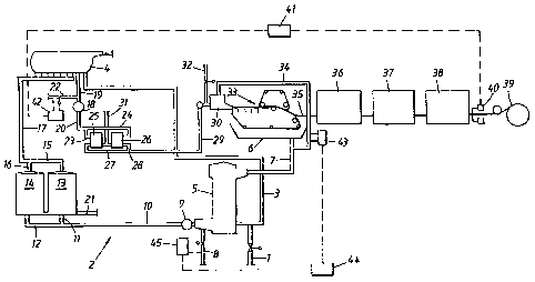
Figure 1 is a schematic illustration of one embodiment of the inventive
method.
A thick pulp suspension is fed into the short circulation 2 through the
conduit 1. The thick pulp suspension contains pulp fibres (whether or not one
type of pulp
fibre or several, e.g. two, types of pulp fibres is included will depend on
the type of paper
to be produced), water (predominantly white water) filler (originating from
the paper broke
slurry) and one or more paper chemicals. The thick pulp suspension fed into
the short
circulation 2 through the conduit I may have a pulp concentration of 2 to 4%.
The thick pulp suspension is introduced in the conduit 3, which contains
white water originating from a deaeration tank 4. The thick pulp suspension is
therewith
diluted and fed into the wire pit 5. The pulp suspension is diluted further
with white water
in the pit, -said water being passed from the wire tray 6 to the wire pit 5
through the conduit
7. This results in a stock. The thick pulp suspension delivered through the
conduit 1 is
sometimes referred to as the stock, including by certain persons skilled in
this art.
Although such language usage is not wrong, we have chosen in this document to
differentiate between thick pulp suspension and stock in order to be able to
describe the
inventive method in a simpler and more readily understood manner.
Fresh filler is fed to the stock in the form of an aqueous dispersion to the
outlet of the wire pit 5, through the conduit 8. The amount of filler added is
determined
primarily by the desired filler content of the finished paper. The method in
which the
addition of filler is regulated in detail will be explained further on in the
text. Different
types of filler have been exemplified in the aforegoing, and the filler chosen
in the
individual case is dependent on several factors.
The stock is passed further through the conduit 10, by means of the pump 9.
Because the filler is delivered close to the pump 9, the filler will be
effectively mixed with
and distributed in the stock. Branch conduits 11 and 12 pass the stock to a
respective
battery 13 and 14 of vortex cleaners or hydrocyclones. Accept pulp is passed
through the
branch conduits 15 and 16 and through the conduit 17 to the aforesaid
deaeration tank 4.
CA 02437046 2003-06-04
WO 02/46525 PCT/F101/01069
Reject is recovered and passed through the conduit 21 to a separate handling
facility,
which is not discussed here. The stock is delivered to the tank 4 through a
large number of
dipper conduits. As the name d.enotes, the stock is deaerated in said tank 4
and stock is
passed from the tank in a substantially air-free state and containing a
certain amount of
5 white water (this latter being mentioned earlier) further along the system.
A foam damping
chemical can be delivered to the stock upstream of position 4, with the
intention of limiting
foaming of the stock.
The stock is fed to a screening operation by means of the feed pump 18, via
the conduits 19 and 20. A first retention agent is delivered to the stock in
conduit 19
10 immediately upstream of the pump 18, through the conduit 22. The retention
agent may be
slurried in or dissolved in white water. Each of the branch conduits 23 and 24
feed the
stock to a respective screen 25 and 26. Accept pulp is fed to the head box 30,
through the
branch conduits 27 and 28 and through the conduit 29. Reject obtained in the
screening
operation is recovered and passed through the conduit 34 to a separate
handling facility,
15 which is not described here. A second retention agent is delivered to the
stock in conduit
29 immediately upstream of the head box 30, through the conduit 32. This
retention agent
may be slurried or dissolved in white water. This results in an essentially
final or finished
stock.
The stock is distributed over a wire in a wire section 33, with the aid of the
head box 30. The solid substance concentration of the stock, essentially
comprised of pulp
fibres, ranges from 0.5 to 1.5 percent in the described position. Concurrently
with the
formation of a paper web on the wire, a large amount of liquid or water is
drained-off both
gravitationally and with the aid of suction boxes. This liquid or said water,
designated
white water, is collected in the wire tray 6. Part of the white water taken
from the wire tray
6 to the wire pit 5 through the conduit 7 is drawn-off through the conduit 34
and returned
to the head box 30 for final dilution of the stock inside the head box 30 and
in a particular
part thereof.
The resultant, coherent paper web 35 is passed to a press section 36 and
thereafter to a pre-dryer 37 and then to an after-dryer 38, whereafter it is
finally rolled-up
on a reeling drum.(tambour) 39.
The content of filler in the finished paper, for instance given in a
percentage
of the weight of the paper, is determined intermittently by means of a
measuring apparatus
CA 02437046 2003-06-04
WO 02/46525 PCT/F101/01069
16
40, which may be a traversing type in accordance with what has earlier been
described.
The measurement signal, i.e. the measured filler content, is sent to a filler
content regulator
41, which sends a signal to a flow regulator 42 that controls the flow of
retention agent to
be supplied via the conduit 22. More specifically, the valve seated in the
conduit 22 is
controlled in a known manner to open wider when desiring a higher flow of
retention agent
and to close accordingly such as to reduce the through-passage of retention
agent when
desiring a reduction in the flow of retention agent. The flow regulating
system also
includes a flow meter by means of which it can be ensured that the desired
amount of
retention agent will actually flow through the conduit 22. In order to
minimise disturbances
in the filler content during a change in the production of the paper machine,
metering of
the retention agent can be given a feed-forward. signal so that it will
automatically follow
the change in production. An increase=in-production requires an increase in
the amount of
retention agent metered to the system. The feed-forward facility is designed
so that a given
percentage change in production will result in the same percentage change in
the amount of
retention agent metered to the system. This takes place over and above the
described
control relating to the measured filler content of the paper.
There is coupled to the conduit 34, through which white water flows, an
apparatus 43 for intermittently measuring the filler concentration and/or the
total
concentration in the white water. A typical measuring apparatus includes a
transparent
measuring cell through which a very small volume of white water is caused to
flow. The
manner in how measuring is effected has been described in more detail earlier.
A signal
which describes, e.g. the measured filler concentration in grams per litre of
white water is
sent from the measuring apparatus 43 to the filler concentration regulator.
44. A signal is
sent from the regulator 44 to a flow regulator 45, which controls the flow of
filler to be
delivered to the system, via the conduit 8. This regulator 45 operates in a
similar manner to
the regulator 42 and also includes a flow meter in this case.
, In order to minimise disturbances in the filler concentration of the white
water during a change in the production of the paper machine, the filler flow
'can be given a
forward-feed signal so that it will automatically follow changes in filler
requirement.
Increased production or an increase in the control value in respect of filler
in the paper
gives, in the long run, a need to increase the amount of filler metered to the
system. By
multiplying the production of the paper machine by the control value for the
filler content
CA 02437046 2003-06-04
WO 02/46525 PCT/F101/01069
17
of the paper, there is obtained a value for calculated filler consumption. The
feed-forward
coupling is designed so that a given percentage change in the calculated
filler consumption -
will also give the aforedescribed adjustment in respect of the measured
concentration of
filler in the white water.
In the case of the described embodiment of the invention, only one filler is
supplied (at position 8), whereas two retention agents are supplied (at
positions 22 and 32).
With regard to the retention agent supplied at position 32, which agent may
consist of
bentonite clay for instance, the amount of agent supplied has been chosen to
have a fixed
value, i.e, o.ne and the same flow of retention agent. is supplied to one and
the same flow of.
stock. The magnitude of this fixed charge of retention agent will depend on a
number of
factors, such as on the desired amount of filler in the finished paper and the
amount of
filler charged to the system per unit of time, and also on the magnitude of
the amount of
supplementary retention agent charged to the system at position 22. When using
bentonite
clay as retention agent, it has been found that an optimal effect is obtained
when said agent
is added to the system as close as possible to the head box.
With regard to the retention agent in position 22, which agent may, for
instance, comprise a synthetic water-soluble organic polymer, the amount of
agent charged
varies in accordance with requirements. It has been found that in order to
obtain a good
effect with such a retention agent, the agent should be charged to the system
immediately
upstream of the feeder pump 18, as shown in Figure 1. Although it is fully.
possible to add
the retention agent earlier in the flow direction within the short
circulation, there is a risk
that the retention agent will then take several paths and be recycled,
therewith causing the
agent to lose electric charge and not being utilised optimally in the paper
forming process,
i.e. in the wire section 33.
In accordance with the earlier described control philosophy, the varying
addition of retention agent in position 22 is effected in the following way.
When wishing to produce a paper that includes a given filler in a given
quantity, for instance 21% it is known through experience that a given
approximate flow of
filler must be delivered through the conduit 8. It is also known through
experience that in
the current conditions, it is suitable to add a given retention agent to the
system in a fixed
amount, via the conduit 32. It is also known from experience what. the
approximate.
CA 02437046 2003-06-04
WO 02/46525 PCT/F101/01069
18
addition of said second retention agent shall be, via the conduit 22. When the
paper
manufacturing process is well under way, the filler content of the'finished
paper is
measured at short intervals in position 40. If these measurements show that
the filler
content or concentration of the paper is, for instance, 21.5% instead of
21.0%, the control
function is activated. The measured value is sent in signal form from position
40 to the
filler content regt.~-, or 41, and said filler content regulator 41 sends to
the retention agent
flow regulator 42 a signal which indicates that the flow. of retention agent -
shall be -
decreased to a certain extent, because the measurement just taken shows that
the filler
content of the paper is slightly too high. The reduced supply of retention
agent to the stock
is quickly effective in reducing the adsorption of filler in the paper web
being formed on
the wire, therewith obtaining the desired filler content of 21 fo in the
paper. If the measured
filler content is lower than that desired, for instance 20.5%, the flow of
retention agent is
increased through the conduit 22 to a corresponding degree. The increase
supply of
retention agent to the stock quickly becomes. effective in an increased
adsorption of filler in
the paper web on its way being formed on the wire, therewith obtaining the
desired filler
content of 21 /a in the paper.
In order to achieve the aforedescribed, the filler concentration in the
system,
including in the white water, need not have a fixed relationship with the
amount of
retention agent added to the system and the content of filler in the paper
produced, since it
is also possible to maintain a correct filler content in the paper when the
continual addition
of filler over a longer period of time is excessively low and results in a
constant reduction
in filler concentration in the white water. There is, of course, a lower limit
for depletion of
filler in the buffer system.
The structure of the filler content regulator 41 is known to the art. A
feedback regulator is normally used. The most common type of regulator is
designated PID
regulator and operates exclusively on the basis of "control error" e, and the
following
relationship prevails between control error e and control signal u;
t
u= K[e + Tn de + 1 J e(s)ds]
dt Ti
The control signal is composed of three terms, where P denotes the
proportional term, which is proportional to the error, D denotes the
derivative term, which
CA 02437046 2008-06-05
19
is proportional to the derivative of the error, and 1 is the integral term,
which is
proportional to the derivative of the error. This is taught, for instance, in
a booklet form
Lund's Tekniska Hogskola entitled "Reglerteknik, en elementar introduktion",
written by
Karl Johan Astrom, Lund Institute of Technology, published in 1981. The
different
terms are combined additively, in the formula. A desired function is set in
the
regulator, by adjusting the three constants K, Tl and TD. A number of
different
methods are available for adapting these constants to the process to be
regulated.
One usable method is designated the Lambda method.
As earlier mentioned, the flow of filler through the conduit 8 is essentially
at
least partially dependent of the filler content of the paper produced, in
other words the
amount of filler that is constantly adsorbed by and incorporated in the paper
web formed
on the wire in the wire section 33.
The filler concentration of the white water is checked at given intervals with
the aid of the measuring apparatus 43. Normally, the desired level of the
filler
concentration in the short circulation is one and the same for a given paper
quality. This
has to do with the runability of the paper machine. It has been found
beneficial with
respect to the running of the paper machine to maintain the filler
concentration in the
system, including the filler concentration of the white water, constant over
the passage of
time. The control value may, for instance, be 4 grams per litre. If the
measured value is 3.8
grams per litre, this value is sent to the filler concentration regulator 44
in signal form. This
regulator sends, in turn, to the filler flow regulator 45 a signal to the
effect that the flow of
filler in the conduit should be increased, which is effected by opening the
valve in the
conduit 8 connected to the regulator 45 still wider. The flow regulator system
also includes
a flow meter by means of which it is ascertained whether or not the intended
amount of
flow actually flows through the conduit 8. If it is found that the value
measured is too high,
for instance 4.2 grams per litre, the flow of filler through the conduit 8 is
reduced to a
corresponding degree.
The filler concentration regulator 44 is of a known kind and may be of the
same type as that earlier described, i.e. as the regulator located in position
41. The control
system constructed around the regulator 44 takes into account that the buffer
system for the
filler in the short circulation, including all white water, is slow to adjust.
In other words,
even though the flow of filler is greatly increased in a certain position, it
will take a long
time before the punctiform significant increase in filler will result in an
increase in the
CA 02437046 2003-06-04
WO 02/46525 PCT/F101/01069
filler concentration in the total, very large, volume of white water. The
control program for
the regulator 44 is generally similar to the control program for the filler
content regulator
41.described above.
As will be seen from the flowchart illustrating the production of filler-
5 containing paper in accordance with Figure 1, the long circulation based on
white water
(for instance taken somewhere along the conduit 7) is not included, and
neither are all the
work-up stations for the thick pulp suspension delivered to the short
circulation through the
conduit 1. This has been excluded for reasons of scope and clarity.
10 Example 1
The inventive method has been tested in a paper machine of a kind that
coincided to a large extent with the flow chart according to Figure 1, for the
production of
filler containing fine paper. Comparisons were made with conventional
technology for the
production of such paper.
15 A thick pulp suspension was fed through the conduit I at a flow rate of
16,500 litres per minute. The starting material for the thick pulp suspension
was 60% fresh
pulp delivered from an adjacent pulp mill, and 40 0o paper broke. In turn, the
fresh pulp
comprised 65% birch sulphate, pulp having a brightness of 90% ISO, and 35%
pine
sulphate pulp having a brightness of 90% ISO. Each of the two fresh pulps were
refined
20 per se before being mixed in a mixing vessel, into which the slushed paper
broke was also
fed. The paper broke had a filler content of about 21.5 fo, and the filler
comprised
precipitated calcium carbonate (PCC). The incoming thick pulp suspension thus
contained
a significant amount of filler, which can be readily estimated. Stock starch
was added to
the thick pulp suspension on its way to the conduit 1.
Fresh filler in'the form 'of 52 percentage PCC was delivered through the
conduit 8 at an approximate flow rate of 90 litres per minute. The filler
density was 770
grams per litre. Small quantities of a number of colour tints were added at
the same time.
Additional paper chemicals, including fluorescent whitening agent, were added
further
forward in the short circulation.
A first retention agent in the form of a synthetic polymer having a density of
4 g/I was delivered through the conduit 22. The flow rate of this retention
agent was, on
average, about 50 litres per nsinute.
CA 02437046 2003-06-04
WO 02/46525 PCT/F101/01069
21
A second retention agent in the form of bentonite clay having a density of
35 grams per litre was delivered to the system via the conduit 32. The flow
rate of this
retention agent was fixed and constituted 30 litres per minute throughout.
The stock leaving the head box 30 had a solid substance content of
0.9-1.0%. The control value for the filler content of the finished paper was
21.5%, and the
weight per unit area of the paper was 80 grams per square metre. The machine
speed was
about 970 metres per minute, resulting in a production of about 30 tonnes of
paper per
hour. The finished paper had a moisture content of about 4.5%.
The paper was surface sized in a film press at a position late in the paper
manufacturing chain. The surface size was applied in an amount corresponding
to about 4
grams per square metre. Although no film press has been shown in the flowchart
of Figure
1, the press was placed immediately downstream of the pre-dryer 37 in the
paper machine
concerned.
Figure 2 illustrates the filler content of the finished paper over four
calendar
days when using conventional technology in producing filler-containing paper,
and also the
filler content of the finished paper over a following four calendar-day period
when using
inventive technology in the production of filler-containing paper.
By conventional technology is meant, among other things, that the filler
content of the paper is measured in position 40 and also the filler
concentration in the white
water at position 43. However, the measured filler content of the paper is not
used to
control the addition of retention agent in position 22 but is used for
controlling the addition
of filler at position 8. The control was carried out so that if the measured
value of the filler
content of the paper was higher than the desired valuej. e. the control value,
the flow of
filler was reduced in position 8, whereas if the measured value was too low,
the flow of
filler was increased in position 8. Moreover, the flow of retention agent in
position 22 was
controlled so that if the filler concentration in the white water, i.e. in
position 43, was
higher than the control value, the flow of retention agent was increased in
position 22,
whereas if the measured value of the filler concentration was too low, the
flow of retention
agent was reduced in position 22.
The filler content of the finished paper when applying the aforedescribed
conventional control technology is shown to the left of the arrow in Figure 2.
As will be
CA 02437046 2003-06-04
WO 02/46525 PCT/F101/01069
22
seen, the filler content varies greatly around the desired control values. The
system has
even reached a howling in any occasion.
At the time marked with an arrow in Figure 2, a departure from the
aforedescribed conventional control technology was made, insofar as the signal
for the
measured filler content of the paper at position 40 was sent to the filler
content regulator
41, which, in turn, sent a signal to the retention agent flow regulator 42 in
accordance with
the Figure 1 illustration and in accordance with the inventive control
technology described
above in detail. When applying the novel control technology, measuring of the
filler
concentration in the white water in position 43 was released during the first
calendar day
from-the automatic and computer controlled control system. Instead, metering
of filler at
position 8 was effected manually by the operators during this calendar day.
It will be seen from Figure 2 that a control value for the filler content in
the
finished paper of 21.5% was used over a period of about 2.5 calendar days when
practising
the invention. The control value was then switched to 22.0%, which was
followed by a
short period in which the old control value was used, i.e. the value of 21.5%,
and the test
run was terminated with a control value of 22%.
The superiority of the novel control technology over conventional control
technology is clearly evident from Figure 2. When applying the novel
technology, the
variation in the filler content of the finished paper is reduced significantly
in relation to the
old and conventional technology. The standard 'deviation in the filler content
of
manufactured paper'has been calculated for one calendar day on each side of
the arrow in
Figure 2 at a control value of 21.5%. In the case of the traditional control
technology, the
standard deviation was 0.95 and in the case of the inventive control
technology the
standard deviation was 0.14, in other words the variation in filler content of
the paper was
improved almost seven times when practising the inventive control technology.
The automated and computer controlled system for metering filler in
position 8 on the basis of the filler concentration measured in the white
water, in,position
43 was activated after about one calendar day. How that works has been
described in detail
earlier.
As will be evident from Figure 3, the control value was 4 grams per litre
both in respect of conventional control technology (to the left of the arrow)
and with
respect to a preferred embodiment of the inventive control technology (to the
right of the
CA 02437046 2003-06-04
WO 02/46525 PCT/F101/01069
23
arrow). The variation around the control value for the filler concentration
also varies in a
surprisingly significant manner in this case. It has been found that a low
variation around
the control value for the filler concentration in the white water is
beneficial with respect to
the drivability of the paper machine concerned.
In the aforedescribed test run carried out in accordance with the invention,
data relating to the filler content of the paper was obtained every twenty
seconds, while
information relating to filler concentration in the white water was obtained
every four
seconds. The use of precisely'these measuring inte'rvals is in no way
mandatory, but that
the measuring intervals can be determined individually and are dependent on
the type of
measuring apparatus used, among other things.
A study of Figures 2 and 3 will show that it is not absolutely necessary to
begin to control the addition of filler to the system on the basis of the
filler concentration
measured in the white water in order to obtain an essentially constant filler
content in the
paper day after day, although such a measure is preferred chiefly for other
reasons. In the
described test run, control of the filler addition in position 8 in accordance
with a preferred
embodiment of the invention was not commenced until after one calendar day.
Despite
this, the paper had the correct filler content after only some ten minutes
subsequent to
starting the test in accordance with the invention.
When the non-compulsory "second" control was started-up, the addition of
filler in position 8 was changed each time the measurement taken in position
43 showed
that it was appropriate to do so. In other words, a small change could be made
to the flow
of filler during long periods each fourth second. It is in no way absolutely
necessary to do
so, since it is fully possible to make a relatively significant change in the
flow of filler on
the basis of a given measurement in position 43, over -a given period of time
which
experience has shown will result in a general increase in the filler
concentration of the
entire system after a given, relatively long period of time, and check that
the measurements
in position 43 follow a well-known pattern during said time period, Thus, it
is. not a
catastrophe if the flow of filler suddenly ceases in position 8 for some
possible unintended
reason,..and that-thesupply of filler is stopped for a limited period.of time.
In principle, the conditions are different with respect to the addition of
retention agent in position 22. If, in this case, the command given by the
control system to
CA 02437046 2003-06-04
WO 02/46525 PCT/F101/01069
24
increase the flow of retention agent is ignored, the paper will obtain an
excessively low
filler content during essentially this ignoring period.
It is mentioned in conclusion that there are found curves which are similar
to the curve shown in Figure 2 and which confirm that switching of the filler
content in
manufactured paper from one level to another can be effected much more rapidly
with the
inventive technology than with conventional technology. This fact also
contributes towards
minimising the volume of paper that need be scrapped. The fact that paper is
still scrapped
is, among other things, due to the fact that quality parameters other than
filler content can
deviate from set measurement values. The aforesaid curves have not been
included for
reasons of space and scope.