Note: Descriptions are shown in the official language in which they were submitted.
CA 02437049 2003-06-02
WO 02/056813 PCT/US02/01505
DISPOSABLE ABSORBENT GARMENT HAVING IMPROVED APPEARANCE
AND SUSTAINED FIT
FIELD OF THE INVENTION
The present invention relates to absorbent articles such as diapers,
incontinence briefs,
training pants, diaper holders and liners, sanitary hygiene garments, and the
like. More
particularly, the present invention relates to absorbent articles providing
improved
appearance and/or improved sustained dynamic fit during use.
BACKGROUND OF THE INVENTION
Absorbent articles such as diapers and training pants tend to slide downward
on the
body of the wearer, especially when loaded with excreta. This relative
movement creates
gaps between the article and the body, through which leakage can occur. It
also creates
wrinkles that detract from the desirable garment-like appearance of the
article. The designs
of absorbent articles typically include features intended to sustain the
proper fit of the
absorbent article on the body. However, these features known in the art are
only partially
effective in sustaining fit, tend to cause discomfort for the wearer, and/or
make application
and/or removal of the article difficult.
For example, the designs of many absorbent articles depend upon a waist
feature to
counteract the downward force of gravity by restricting the size of the waist
opening.
However, the wearer of an absorbent article often has a protuberant abdomen,
rather than a
well-defined waist. The waist edge of the absorbent article will naturally
slide downward
from its initial position on the protuberant abdomen to the area of a diagonal
support zone
lying across the small of the back, over the hip joints, and across the lower
abdomen. Some
designs use friction to resist relative movement at the waist, with the waist
feature providing
the required normal force by generating circumferential tension around the
body. However,
when the abdomen becomes larger than its initial size, the waist feature
naturally seeks a
position of lower tension off the expanded abdomen. Because the article is
restrained from
moving upward, the waist feature typically moves downward toward the diagonal
support
zone in this situation. When the abdomen becomes smaller, the article also
tends to move
1
CA 02437049 2003-06-02
WO 02/056813 PCT/US02/01505
downward, because the tension and the frictional resistance diminish. When a
waist feature
is designed to generate a high force in an attempt to minimize downward
movement, the
greater force often causes discomfort to the wearer and/or creates pressure
marks on the
body. The greater force may also tend to move the article downward, and/or
make
spreading of the waist opening for application and/or removal of the article
difficult.
The designs of some absorbent articles include side panels or waist belts
which
supplement or replace waist features. Examples of such absorbent articles are
described in
U.S. Patent 6,120,487 issued September 19, 2000, and U.S. Patent 5,899,895
issued May 4,
1999, which are hereby incorporated herein by reference. These features tend
to exert
excessive force on areas of the body where they are stretched a greater amount
relative to
other areas, causing discomfort and/or pressure marks on the body. Also, when
the elastic
components move toward positions where they are stretched a lesser amount,
they tend to
bunch and/or slide together such that the forces they exert are concentrated
on a smaller area
of the body, often causing discomfort and/or pressure marking. Some side
panels also
expand and contract to maintain contact of the article about the legs of the
wearer. In the
designs of some such side panels, an elastic component is angled with respect
to the main
waist feature and has one end located on or near the front edge of the waist
opening and
another end located on or near the back edge of the leg opening. Such an
elastic component
which is angled downward toward the back exerts a downward force on the front
portion of
the article, adding to the other forces described above in tending to move the
absorbent
article downward and away from the position in which it is initially fit onto
the body.
In some designs of absorbent articles, the front edge of the waist opening
curves
downward to fit below or at the abdominal crease. Examples of such absorbent
articles are
described in U.S. Patent 5,358,500 issued October 25, 1994, which is hereby
incorporated
herein by reference. Because they are initially fit in the area of the
diagonal support zone,
these low-cut articles often have better sustained fit than articles having
higher waist
openings. However, several desirable properties are relinquished in exchange
for this
improvement in sustained fit. The risk of leakage from such a low-cut
absorbent article is
generally greater, especially for a male wearer, whose urinary stream is often
directed
toward the waist. The appearance of such a low-cut article differs appreciably
from that of a
2
CA 02437049 2003-06-02
WO 02/056813 PCT/US02/01505
durable garment or of an absorbent article having the garment-like appearance
desired by
many users. Such a low-cut absorbent article has less area over which to
distribute the
absorbent core and thus an absorbent core of a given volume may generally be
of greater
thickness in such a low-cut article.
Thus, it would be beneficial to provide an absorbent article designed to
sustain the
proper fit of the article on the body. It would also be beneficial to provide
an absorbent
article having improved appearance throughout its period of use. It would be
of further
benefit to provide an absorbent article having a reduced possibility of
leakage.
Additionally, it would be of benefit to provide an absorbent article having
easy application
and/or removal.
SUMMARY OF THE INVENTION
The present invention provides absorbent articles, such as diapers,
incontinence
briefs, pull-on diapers, training pants, feminine hygiene garments, and the
like, which may
provide some or all of the benefits of improved sustained fit on the body,
improved
appearance through the period of use, and improved comfort for the wearer.
Such an absorbent article is intended to be fit about a wearer's body to
contain
excreta and/or bodily exudates. The absorbent article has a containment
assembly having
a front waist region, a back waist region opposed to the front waist region, a
crotch region
disposed between the front waist region and the back waist region, a front end
edge, a
back end edge, a topsheet, a backsheet, and an absorbent core disposed at
least partially
between the topsheet and the backsheet. The absorbent article also has at
least one waist
feature disposed substantially adjacent either the front end edge or the back
end edge.
Furthermore, the absorbent article has at least one diagonal support member
designed to
support the absorbent article on the body substantially in the diagonal
support zone which
lies across the small of the back over the hip joints and across the lower
abdomen. When
the absorbent article is worn, a first end of the diagonal support member
preferably lies
substantially adjacent the back waist region of the absorbent article and a
second end of
the diagonal support member preferably lies substantially adjacent the lower
abdomen of
the wearer's body.
3
CA 02437049 2003-06-02
WO 02/056813 PCT/US02/01505
The diagonal support member preferably bears the major portion of the weight
of
the absorbent article and resists downward force caused by changes in bodily
shape or
dimension. As a result, the waist feature may be subjected to only minimal
downward
force. Therefore, the waist feature may be designed to provide only enough
circumferential tension to hold itself in position on the body and thus avoid
causing
discomfort for the wearer and/or pressure marking on the wearer's body.
The absorbent article may thus provide a garment-like high-waisted appearance,
gentle tension around the waist to avoid discomfort and/or pressure marking,
good
leakage protection, good sustained fit, and easy application and removal.
BRIEF DESCRIPTION OF THE DRAWINGS
While the specification concludes with claims particularly pointing out and
distinctly claiming the subject matter which is regarded as forming the
present invention, it
is believed that the invention will be understood from the following
description which is
provided in conjunction with the accompanying drawings, in which like
designations are
used to designate substantially identical elements, and in which:
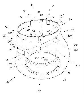
Figure 1 is a side perspective view of a pre-closed absorbent article
embodiment of the
present invention;
Figure 2 is a side perspective view of a non-pre-closed absorbent article
embodiment of the
present invention in assembled form;
Figure 3 is a simplified plan view of the article in Figure 2, laid out flat
with the inner
surface facing the viewer, showing various sections and structural elements
and having
portions cut away to reveal underlying structure;
Figure 4 is another simplified plan view of the article in Figure 2, laid out
flat with the outer
surface facing the viewer and showing various sections and structural
elements;
4
CA 02437049 2003-06-02
WO 02/056813 PCT/US02/01505
Figure 5 is a side perspective view of an alternative embodiment of the
absorbent article of
the present invention in assembled form;
Figure 6 is a simplified plan view of the absorbent article in Figure 5, laid
out flat and
showing various sections and structural elements;
Figure 7 is a simplified plan view of an alternative embodiment of the
absorbent article of
the present invention, laid out flat and showing various sections and
structural elements;
Figure 8 is a side perspective view of an alternative pre-closed embodiment of
the absorbent
article of the present invention;
Figure 9 is a simplified plan view of the absorbent article in Figure 8 prior
to closure, laid
out flat and showing various sections and structural elements;
Figure 10 is a side perspective view of an alternative embodiment of the
absorbent article of
the present invention in assembled form;
Figure 11 is a simplified plan view of an alternative embodiment of the
absorbent article of
the present invention, laid out flat and showing various sections and
structural elements;
Figure 12 is a side perspective view of an alternative embodiment of the
absorbent article of
the present invention in assembled form;
Figure 13 is a side view of a portion of the torso of a wearer, such as an
ambulatory child, in
an upright or standing position;
Figure 14 is a front view of a portion of the torso of a wearer, such as an
ambulatory child,
in an upright or standing position;
CA 02437049 2003-06-02
WO 02/056813 PCT/US02/01505
Figure 15 is a side view of a portion of the torso of a wearer, such as an
ambulatory child, in
an upright or standing position, wearing an absorbent article of the present
invention; and
Figure 16 is a front view of a portion of the torso of a wearer, such as an
ambulatory child,
in an upright or standing position, wearing an absorbent article of the
present invention.
DETAILED DESCRIPTION OF THE INVENTION
The term "absorbent article" herein refers to a device which absorbs and
contains
excreta and/or bodily exudates and, more specifically, refers to a device
which is placed
against or in proximity to the body of the wearer to absorb and contain the
excreta and/or
exudates discharged from the body. The term "unitary absorbent article" herein
refers to
an absorbent article which is formed of separate parts united together to form
a
coordinated entity so that separate manipulative parts, such as a separate
holder and/or
liner, are not required. The term "disposable article" herein refers to an
article which
generally is not intended to be restored or reused, but is instead intended to
be discarded
after a single use. The term "diaper" refers to an absorbent article generally
worn by
infants and incontinent persons about the lower torso. The present invention
is applicable
to absorbent articles such as diapers, pull-on diapers, training pants,
incontinence briefs,
incontinence undergarments, absorbent inserts, diaper holders and liners,
feminine
hygiene garments, and the like.
An exemplary embodiment of an absorbent article of the present invention is
the
unitary disposable absorbent article, diaper 20, shown in Figure 1 in pre-
closed form
suitable for use as a pull-on diaper or training pant. The diaper 20 in
conventional non-
pre-closed form, is shown in Figure 2. The diaper 20 of Figure 2 is also shown
in a flat
and uncontracted state in Figure 3 with the portion of the diaper 20 which
faces the wearer
oriented toward the viewer, and in Figure 4 with the portion of the diaper 20
which faces
away from the wearer oriented toward the viewer. In some of the drawings,
portions of
the structure have been cut away to more clearly show the construction of the
exemplary
absorbent articles. Elements of the diaper 20 which are substantially
identical in different
embodiments and/or in different drawings are designated herein by the same
numerals.
6
CA 02437049 2003-06-02
WO 02/056813 PCT/US02/01505
The diaper 20 preferably includes a containment assembly 22, a waist feature
34,
and a diagonal support member 200. The diaper 20 has a front waist region 36,
a back
waist region 38 opposed to the front waist region 36, and a crotch region 37
located
between the front waist region 36 and the back waist region 38. The periphery
of the
diaper 20 is defined by the outer edges of the diaper 20 in which side edges
50 lie
generally parallel to the longitudinal centerline 100 and the front end edge
52 and back
end edge 54 lie generally parallel to the lateral centerline 110 of the diaper
20 and extend
between the side edges 50.
The containment assembly 22 of the diaper 20 preferably includes a liquid
pervious topsheet 24, a liquid impervious backsheet 26, and an absorbent core
28 which is
preferably positioned between at least a portion of the topsheet 24 and the
backsheet 26.
The containment assembly 22 constitutes the main structure of the diaper with
other
features added to form the composite diaper structure. The containment
assembly 22 has
an inner surface 23 which generally is in contact with the body or in close
proximity to the
body when the article is worn. The containment assembly 22 also has an outer
surface 25
opposed to the inner surface 23 and which generally is in contact with or in
close
proximity to any garment being worn. The topsheet 24, the backsheet 26, and
the
absorbent core 28 may be assembled in a variety of configurations well known
in the art.
Exemplary containment assembly structures are described in U.S. Patent
5,899,895 issued
May 4, 1999 and U.S. Patent 6,120,487 issued September 19, 2000, which are
hereby
incorporated herein by reference.
The backsheet 26 is generally that portion of the diaper 20 which is disposed
adjacent the garment-facing surface 45 of the absorbent core 28 and which
prevents the
excreta and/or exudates contained therein from soiling articles which may
contact the
diaper 20, such as bedsheets and undergarments. The term "disposed" refers
herein to the
arrangement of an element in a particular physical relationship to other
elements of the
absorbent article. In preferred embodiments, the backsheet 26 is substantially
impervious
to liquid and may comprise any suitable thin plastic film known in the art,
including a
breathable film. Exemplars of suitable backsheet films include those
manufactured by
7
CA 02437049 2003-06-02
WO 02/056813 PCT/US02/01505
Tredegar Industries, Inc., or Terre Haute, Indiana, USA, and sold under the
trade names
X15306, X10962, and X10964.
The backsheet 26 may be joined to the topsheet 24, the absorbent core 28 or
any
other element of the diaper 20 by any attachment means known in the art. The
term
"joined" refers herein to the attachment together of elements of the absorbent
article,
either by direct affixment of a first element to a second element or by
affixment of the
first element to an intermediate element which is affixed to the second
element. For
example, the attachment means may include a uniform continuous layer of
adhesive, a
patterned layer of adhesive, or an array of separate lines, spirals, or spots
of adhesive.
Exemplars of suitable adhesives include those manufactured by H.B. Fuller
Company of
St. Paul, Minnesota, USA and marketed as HL-1620 and HL-1358-XZP.
Alternatively,
the attachment means may comprise heat bonds, pressure bonds, ultrasonic
bonds,
dynamic mechanical bonds, or any other suitable attachment means or
combinations of
attachment means known in the art.
The topsheet 24 is preferably disposed adjacent the body-facing surface 47 of
the
absorbent core 28 and may be joined to the absorbent core 28 and/or to the
backsheet 26
by any attachment means known in the art. The topsheet 24 is preferably
compliant, soft-
feeling, and non-irritating to the wearer's skin. Preferably, at least a
portion of the
topsheet 24 is liquid pervious, permitting liquids to readily penetrate
through its thickness.
A suitable topsheet may be manufactured from a wide range of materials known
in the art,
such as porous foams, reticulated foams, apertured plastic films, or woven or
nonwoven
materials of natural fibers such as wood or cotton fibers, or synthetic fibers
such as
polyester or polypropylene fibers, or a combination of natural and synthetic
fibers. If the
topsheet 24 includes fibers, the fibers may be spunbond, carded, wet-laid,
meltblown,
hydroentangled, or otherwise processed as is known in the art. An exemplar of
a suitable
topsheet non-woven material is manufactured by Veratec, Inc., a division of
International
Paper Company of Walpole, Massachusetts, USA, and is designated P-8.
The absorbent core 28 may comprise any absorbent material which is generally
compressible, conformable, non-irntating to the wearer's skin, and capable of
absorbing
and retaining liquids such as urine and other bodily exudates. The absorbent
core 28 may
8
CA 02437049 2003-06-02
WO 02/056813 PCT/US02/01505
be manufactured in a wide variety of sizes and shapes, for example,
rectangular,
hourglass, "T"-shaped, asymmetric, etc. The absorbent core 28 may include any
of a wide
variety of liquid-absorbent materials commonly used in disposable diapers and
other
absorbent articles, such as comminuted wood pulp, which is generally referred
to as
airfelt, cellulose wadding, meltblown polymers, chemically stiffened,
modified, or cross-
linked cellulosic fibers, tissue, absorbent foams including those prepared
from
polymerization of a high internal phase emulsion, superabsorbent polymers,
absorbent
gelling materials, or any other known absorbent material or combinations of
materials.
Exemplary absorbent core structures are described in U.S. Patent 4,610,678
issued
September 9, 1986 and U.S. Patent 5,260,345 issued November 9, 1993, both of
which
are hereby incorporated herein by reference.
The diaper 20 of the present invention includes at least one waist feature 34
as
shown, for example, in Figure 1 and other figures. The waist feature 34
preferably is
disposed at least longitudinally outwardly from at least one of the waist
edges 56 of the
absorbent core 28 and generally forms at least a portion of the front end edge
52 and/or
the back end edge 54 of the diaper 20. The waist feature 34 may comprise one
or more
separate elements affixed to the diaper 20 and/or may comprise an extension of
another
element of the diaper 20, such as the backsheet 26 and/or the topsheet 24. The
waist
feature 34 may be substantially inelastic or may be at least laterally
elastically extensible
to dynamically fit at the wearer's waist. The terms "elastic" and "elastically
extensible"
refer herein to the property of a material and/or an element of the diaper 20
whereby the
material and/or the element can be elongated to a practical extent upon the
application of
tension and will substantially return to its original length or near its
original length after
the tension is released. Disposable diapers often have a waist feature 34
disposed in both
the front waist region 36 and the back waist region 38. The waist feature 34
may be
constructed in any of several different configurations known in the art.
Exemplary waist
feature constructions include those described in U.S. Patent 4,515,595 issued
May 7, 1985
and U.S. Patent 5,221,274 issued June 22, 1993, both of which are hereby
incorporated
herein by reference.
9
CA 02437049 2003-06-02
WO 02/056813 PCT/US02/01505
In the diaper 20 of the present invention, the waist feature 34 preferably
provides
generally only minimal lateral force, that is, lateral force sufficient only
to hold the front
waist region 36 and the back waist region 38 substantially in contact with the
body. This
level of lateral force is adequate because the waist feature 34 preferably is
subjected to
only minimal downward force, due to the diaper 20 being configured such that
the
diagonal support member 200 resists downward force. As a result, the waist
feature 34
generally remains in position substantially where it is initially fit, with
the front end edge
52 remaining near the navel 11 of the wearer's body. The term "downward"
refers herein
to a direction generally from the head toward the feet on the body of a wearer
in all bodily
positions and postures.
In some embodiments, the diaper 20 preferably includes a fastening system 40
as
shown, for example, in Figure 1 and other figures. The fastening system 40
preferably
maintains the front waist region 36 and the back waist region 38 in a hoop
configuration
such that lateral force exerted by the waist feature 34 and/or another element
of the diaper
20 contributes to circumferential tension which is aligned substantially
parallel to the
front end edge 52 and back end edge 54, which form the waist opening 21 when
the
diaper 20 is worn. The fastening system 40 preferably is disposed at least
partially
adjacent at least a portion of the side edges 50 of the front waist region 36
and/or the back
waist region 38. In general, the fastening system 40 may comprise any known
fastening
means. For example, the fastening system 40 may comprise surface fasteners
such as tape
tabs, hook and loop fastening components, and/or hermaphroditic fastening
components.
Furthermore, the fastening system 40 may include buttons, hooks, buckles,
and/or other
fastening components. In some embodiments, the fastening system 40 may include
refastenable fastening means that allow the diaper 20 to be opened and re-
fastened, for
ease of fitting on and removal from the body of the wearer and for adjustment
while the
diaper 20 is worn. An exemplar of a suitable fastening system 40 is described
in U.S.
Patent 5,242,436 issued September 7, 1993, which is hereby incorporated herein
by
reference.
In some embodiments, the diaper 20 may be provided in a pre-closed form as
shown, for example, in Figure 1 and Figure 8, suitable for use as a pull-on
diaper, training
CA 02437049 2003-06-02
WO 02/056813 PCT/US02/01505
pant, or the like. The term "pre-closed" refers herein to a form of an article
in which the
article is assembled and ready for use. The pre-closed diaper 20 may have its
opposing
side edges 50 in the front waist region 36 and the back waist region 38 joined
by seams or
welds 42, as shown in Figure 1. The seams or welds 42 may be bonded by any
suitable
bonding means known in the art which is appropriate for the specific materials
employed.
For example, suitable bonding means may include ultrasonic sealing, heat
sealing,
pressure bonding, adhesive bonding, sewing, autogenous bonding, and the like.
The
seams or welds 42 may be permanent, that is, they may be bonded such that
separation of
the joined opposing side edges 50 requires the rupture or other destructive
manipulation
of the bonded materials. A pre-closed diaper 20 may alternatively have its
opposing side
edges 50 fastened together by any suitable fastening means, including those
described
above for the fastening system 40. In some embodiments, the fastening system
40 of a
pre-closed diaper 20 may have refastenable fastening means that allow the
diaper to be
opened and re-fastened, for ease of fitting on and removal from the body of
the wearer
and for adjustment while the diaper 20 is worn. In an embodiment in which a
pre-closed
diaper 20 has a fastening system 40, the fastening system 40 preferably is
disposed at least
partially adjacent at least a portion of the side edges 50 of the front waist
region 36 and/or
the back waist region 38.
The diaper 20 may also include at least one high friction retention zone 70 as
shown, for example, in Figure 1 and other figures. The high friction retention
zone 70
preferably is disposed at least partially on the inner surface 23 of the
containment
assembly 22 in either the front waist region 36 or the back waist region 38. A
function of
the high friction retention zone 70 is to resist movement of the diaper 20
relative to the
surface of the wearer's body and in particular to resist downward movement of
the diaper
20. The high friction retention zone 70 preferably has a coefficient of static
friction to the
body which is at least about twice the coefficient of static friction to the
body of the
material forming the inner surface 23 of the containment assembly 22. The high
friction
retention zone 70 may comprise an area of a coating and/or a patch of a
suitable material.
Examples of suitable coating materials include polymeric materials, rubber-
based
materials, and/or latex or hot-melt materials. Suitable patch materials are
typically thin
11
CA 02437049 2003-06-02
WO 02/056813 PCT/US02/01505
and flexible and can be firmly affixed to the inner surface 23 of the
containment assembly
22. Examples of suitable patch materials include polymeric films, fibrous
sheets, and/or
scrims. Examples of a high friction retention zone 70 are described in co-
pending and
commonly assigned U.S. Patent Application 09/312,997 filed on May 17, 1999,
which is
hereby incorporated herein by reference.
The diaper 20 may also include side panels 30 disposed in the back waist
region
38, in the front waist region 36, or in both the front waist region 36 and the
back waist
region 38 as shown, for example, in Figure 1 and other figures. The side
panels 30 may
be constructed in any suitable configuration known in the art. The side panels
30 may be
elastically extensible. An exemplar of an elastic side panel is described in
U.S. Patent
5,669,897 issued September 23, 1997, which is hereby incorporated herein by
reference.
The diaper 20 may include at least one leg cuff 32 as shown, for example, in
Figure 1 and other figures. Leg cuffs 32 are known variously in the art as leg
cuffs, leg
bands, side flaps, barrier cuffs, and/or elastic cuffs. The leg cuff 32 may be
substantially
inelastic or may be elastically extensible to dynamically fit at the wearer's
leg. The leg
cuff 32 may be constructed in any suitable configuration known in the art,
including those
described in U.S. Patent 4,695,278 issued September 22, 1987, and U.S. Patent
4,795,454
issued January 3, 1989, which are hereby incorporated herein by reference.
The diaper 20 of the present invention also includes at least one diagonal
support
member 200. Examples of the diagonal support member 200 are shown in Figure 1,
Figure 2, and other figures. The diagonal support member 200 is designed to
support the
diaper 20 on the body substantially in the diagonal support zone 13. In Figure
13, which
shows a partial side view of the torso 1 of an infant, the anatomical location
of the
diagonal support zone 13 is shown to lie generally across the small of the
back 3, over the
hips 5, and across the lower abdomen 9 of the wearer's body. The diagonal
support zone
13 is angled downward in the front of the body relative to the waistline plane
17. In the
partial front view of the torso 1 of an infant of Figure 14, the diagonal
support zone 13 is
shown to lie generally across the lower abdomen 9 of the wearer's body.
The diagonal support member 200 preferably is disposed in the diaper 20 so as
to
lie at least partially in the diagonal support zone 13 of the wearer's body
when the diaper
12
CA 02437049 2003-06-02
WO 02/056813 PCT/US02/01505
20 is worn. Figure 15 shows a partial side view of the torso 1 of an infant
and the diaper
20 as worn. As can be seen by reference between Figure 13 and Figure 15, the
front end
edge 52 and the back end edge 54 lie substantially parallel to the waistline
plane 17 and
the diagonal support member 200 lies substantially parallel to the diagonal
support zone
13 when the diaper 20 is worn. Figure 16 shows a partial front view of the
torso 1 of an
infant and the diaper 20 as worn. It can also be seen by reference between
Figure 14 and
Figure 16 that the diagonal support member 200 lies substantially parallel to
the diagonal
support zone 13 when the diaper 20 is worn.
The diagonal support member 200 has a first end 210 and a second end 212. The
first end 210 preferably is disposed so as to lie substantially adjacent the
back waist
region 38 of the diaper 20 when the diaper 20 is worn. The second end 212
preferably is
disposed so as to lie substantially adjacent the wearer's lower abdomen 9 when
the diaper
20 is worn. The first end 210 and the second end 212 define a major diagonal
axis 216 of
the diagonal support member 200. The major diagonal axis 216 preferably is
substantially
parallel to the diagonal support zone 13 of the wearer's body when the diaper
20 is worn.
In various embodiments, the major diagonal axis 216 may preferably be disposed
at an
angle greater than about 5 degrees or at an angle greater than about 15
degrees relative to
the lateral centerline 110 of the diaper 20. Likewise, in various embodiments,
the major
diagonal axis 216 may preferably be disposed at an angle of about 60 degrees
or less or at
an angle of 45 degrees or less relative to the lateral centerline 110. An
angle of about 30
degrees between the major diagonal axis 216 and the lateral centerline 110 has
been found
to be suitable over a wide range of sizes of wearers and of the diaper 20.
The diagonal support member 200 may be disposed at least partially interiorly
to
the formed diaper 20 adjacent the inner surface 23 of the containment assembly
22.
Alternatively, the diagonal support member 200 may be disposed at least
partially
exteriorly to the formed diaper 20 adjacent the outer surface 25 of the
containment
assembly 22. Furthermore, the diagonal support member 200 may be disposed at
least
partially between the topsheet 24 and the backsheet 26. For example, in the
embodiment
shown in Figure 2, the diagonal support member 200 is disposed exteriorly to
the formed
13
CA 02437049 2003-06-02
WO 02/056813 PCT/US02/01505
diaper 20, while in the embodiment shown in Figure 7, the diagonal support
member 200
is disposed between the topsheet 24 and the backsheet 26 of diaper 20.
In general, the diagonal support member 200 may be of any suitable size and/or
shape. The diagonal support member 200 has a width 218 which is measured
substantially at a right angle to the major diagonal axis 216. The diagonal
support
member 200 may have any width 218 suitable for the avoidance of pressure
marking on
the wearer's body and for fitting into the bodily contours generally defining
the diagonal
support zone 13. In some embodiments, the diagonal support member 200
preferably has
a width 218 in the range of about 10 millimeters to about 50 millimeters. It
has been
found that a width 218 of the diagonal support member 200 of about 25
millimeters is
suitable over a wide range of sizes of wearers and of the diaper 20.
The diagonal support member 200 may comprise any material known in the art
which is suitable for the purpose of supporting the diaper 20 as described
above. The
diagonal support member 200 preferably is compliant, soft-feeling, and non-
irritating to
the skin such that it has minimal negative effect on the wearer's comfort
and/or the visual
and/or tactile perception of the user. The diagonal support member 200
preferably is
elastically extensible at least in a direction substantially parallel to its
major diagonal axis
216, but may be substantially inelastic in nature. Suitable materials for use
in the
construction of the diagonal support member 200 include materials used in
other elements
of the diaper 20, such as topsheet 24 material, backsheet 26 material, waist
feature 34
material, side panel 30 material, leg cuff 32 material, elastic strip
material, and the like.
The diagonal support member 200 may comprise a single layer or a laminate of
suitable
materials. Such a laminate may include, for example, nonwoven material, film,
formed
film, scrim material, foam, and/or strip material. In some embodiments, the
diagonal
support member 200 may comprise a structural elastic-like film ("SELF") web. A
structural elastic-like film web is an extensible material that exhibits an
elastic-like
behavior in the direction of elongation without the use of added elastic
materials and is
described in more detail in U.S. Patent No. 5,518,801 entitled "Web Materials
Exhibiting
Elastic-Like Behavior" issued to Chappell, et al. on May 21, 1996, which is
hereby
incorporated herein by reference. Also, the diagonal support member 200 may
comprise
14
CA 02437049 2003-06-02
WO 02/056813 PCT/US02/01505
incrementally stretched material formed by methods such as ring rolling
between meshed
corrugated rolls, stamping with meshing platens, and the like. Examples of
incremental
stretching methods and suitable incrementally stretched materials are
described in U.S.
Patent 5,167,897 issued December 1, 1992, which is hereby incorporated herein
by
reference.
The diagonal support member 200 may be joined to the backsheet 26,'the
topsheet
24, to both the backsheet 26 and the topsheet 24, and/or to any other element
of the diaper
20 by any attachment means known in the art which is suitable for the
materials involved.
For example, the attachment means may include any of those listed above in
reference to
the backsheet 26.
The diagonal support member 200 may be joined to another element of the diaper
20 at least at or near the first end 210 and the second end 212 and/or may be
joined along
any portion of its length or substantially its entire length. Alternatively,
at least some
portion of the diagonal support member 200 may be joined to another element of
the
diaper 20 and at least the first end 210 and/or the second end 212 may be
unjoined to any
other element of the diaper 20. In some embodiments, the unjoined first end
210 or
second end 212 of the diagonal support member 200 may have at least one
diagonal
support fastening system 240. For example, the embodiment of diaper 20 shown
in
Figure 2 has the second end 212 of the diagonal support member 200 joined to
the
containment assembly 22 substantially adjacent the lower abdomen 9 of the
wearer's body
when the diaper 20 is worn and the first end 210 of the diagonal support
member 200
fastened substantially adjacent the back waist region 38 of the diaper 20 by
means of the
diagonal support fastening system 240. In the alternative embodiment shown in
Figure 5
and in Figure 6, the diaper 20 has the first end 210 of the diagonal support
member 200
joined to the containment assembly 22 substantially adjacent the back waist
region 38 of
the diaper 20 and the second end 212 fastened substantially adjacent the lower
abdomen 9
of the wearer's body, when the diaper 20 is worn, by means of the diagonal
support
fastening system 240. The diagonal support fastening system 240 may comprise
any of
the fastening means listed above in reference to the fastening system 40
and/or any other
suitable fastening means. The diagonal support fastening system 240 may be
openable
CA 02437049 2003-06-02
WO 02/056813 PCT/US02/01505
and refastenable to facilitate adjustment of the fit of the diaper 20 on the
body of the
wearer. Furthermore, the diagonal support fastening system 240 may include
distinctive
marks denoting various potential fastening positions of the unjoined first end
210 or
second end 212 of the diagonal support member 200.
In some embodiments, the unjoined first end 210 or second end 212 of the
diagonal support member 200 may pass through a grommet, eyelet or ring
structure 220
enabling the diagonal support member 200 to be used as a drawstring or cinch
strap. For
example, in the embodiment shown in Figure 10, the diagonal support member 200
is
partially disposed between the topsheet 24 and the backsheet 26, the first end
210 of the
diagonal support member 200 is unjoined, and this unjoined first end 210
emerges
through a grommet 220 for use of the diagonal support member 200 as a
drawstring.
In some embodiments, the diagonal support member 200 may comprise a unitary
structure spanning between the first end 210 and the second end 212. For
example, in the
embodiment shown in Figure 2, the diagonal support member 200 is disposed
exteriorly
to the formed diaper 20 and spans between the first end 210 and the second end
212.
Another example of a diagonal support member 200 comprising a unitary
structure is
shown in the embodiment of Figure 7, in which the diagonal support member 200
is
disposed substantially between the topsheet 24 and the backsheet 26 of diaper
20. In this
embodiment, the back end edge 54 has a greater length than the front end edge
52. Thus,
the side edges 50 in the front waist region 36 and the back waist region 38
lie
circumferentially less distantly from the longitudinal centerline 100 in the
front waist
region 36 than in the back waist region 38 when the diaper 20 is worn.
Anatomically, in
this embodiment, the side edges 50 in the front waist region 36 and the back
waist region
38 of the diaper 20 lie substantially adjacent the lower abdomen 9 when the
diaper 20 is
worn. Thus, in this embodiment, the diagonal support member 200 may comprise a
unitary structure spanning between the first end 210 and the second end 212.
Another exemplary embodiment of the diaper 20 in which the diagonal support
member 200 may comprise a unitary structure is shown in Figure 8 and Figure 9.
In this
embodiment, the side edges 50 of the diaper 20 in the front waist region 52
and the back
waist region 54 are substantially non-parallel to the longitudinal centerline
100. Instead,
16
CA 02437049 2003-06-02
WO 02/056813 PCT/US02/01505
the side edges 50 in the front waist region 52 and the back waist region 54
are
substantially angled relative to the longitudinal centerline 100 so as to lie
substantially in
the diagonal support zone 13 of the wearer's body when the diaper 20 is worn.
As shown
in Figure 8, the opposing side edges 50 in the front waist region 52 and the
back waist
region 54 may be joined by seams or welds 42, as described above in reference
to the pre-
closed form of the diaper 20. In such an embodiment, the material which is
bonded in the
seams or welds 42 may have suitable characteristics, as described above, to
substantially
constitute the diagonal support member 200. Alternatively, the diagonal
support member
200 may comprise at least one additional element disposed substantially
parallel to and in
close proximity to side edges 50 in the front waist region 52 and the back
waist region 54
which are angled as shown in Figure 9.
In some embodiments, the diagonal support member 200 and the leg cuff 32 may
constitute a substantially unitary structure, as shown in the exemplary
embodiment of
Figure 12. For example, an elastically extensible diagonal support member 200
may
comprise an extension of the material forming an elastically extensible leg
cuff 32. In
another example, an elastically extensible leg cuff 32 may comprise an
extension of the
material forming an elastically extensible diagonal support member 200. In
such
embodiments, the substantially unitary structure forming the diagonal support
member
200 and the leg cuff 32 may have specific properties in specific portions. For
example, an
elastically extensible unitary structure may have a first elastic modulus in
the portion
forming the leg cuff 32 and a second elastic modulus in the portion forming
the diagonal
support member 200. Similarly, the thickness, width, material composition,
and/or some
other property may be specific to specific portions of what is nonetheless a
substantially
unitary structure forming the diagonal support member 200 and the leg cuff 32.
In some embodiments, the back end edge 54 and the front end edge 52 may have
substantially equal lengths and thus the side edges 50 in the front waist
region 36 and the
back waist region 38 may lie substantially circumferentially equidistantly
from the
longitudinal centerline 100 in the front waist region 36 and in the back waist
region 38
when the diaper 20 is worn. Anatomically, in such an embodiment, the side
edges 50 in
the front waist region 36 and the back waist region 38 lie substantially
circumferentially
17
CA 02437049 2003-06-02
WO 02/056813 PCT/US02/01505
equidistantly from the navel 11 and the small of the back 3 when the diaper 20
is worn. In
such embodiments, the diagonal support member 200 may comprise two or more
discrete
elements. For example, in the embodiments shown in Figure 1 and Figure 11, the
back
end edge 54 and the front end edge 52 have substantially equal lengths and the
diagonal
support member 200 is disposed substantially between the topsheet 24 and the
backsheet
26. As shown in Figure 1 and Figure 11, the diagonal support member 200 may
comprise
at least one front diagonal support element 201 disposed substantially in the
front waist
region 36 and at least one back diagonal support element 203 disposed
substantially in the
back waist region 38 of the diaper 20. The front diagonal support element 201
and the
back diagonal support element 203 preferably are aligned substantially along
the major
diagonal axis 216 of the diagonal support member 200 such that they function
cooperatively to support the diaper 20 on the body substantially in the
diagonal support
zone 13 when the diaper 20 is worn, that is, such that when the diaper 20 is
worn, they act
cooperatively substantially like a diagonal support member 200 comprising a
unitary
structure.
In embodiments in which the diagonal support member 200 comprises two or
more discrete elements, the intermediate ends 214 may be fastened to each
other and/or
may be joined and/or fastened to other elements of the diaper 20, as described
above.
Alternatively, at least one of the intermediate ends 214 may be unjoined to
any other
element of the diaper 20. As described above in reference to the first end 210
and the
second end 212, such an unjoined intermediate end 214 of the diagonal support
member
200 may have at least one diagonal support fastening system 240 and/or may
pass through
a grommet, eyelet, or ring structure 220 enabling the diagonal support member
200 to be
used as a drawstring or cinch strap.
The diagonal support member 200 preferably bears the major portion of the
weight
of the diaper 20, especially when the diaper 20 is loaded with excreta. In
addition, the
diagonal support member 200 preferably resists downward force caused by
changes in
bodily shape or dimension such as an expansion of the abdomen and/or a
transition from a
sitting posture to a standing posture. In order to support the diaper 20 on
the body
substantially in the diagonal support zone 13 of the wearer's body, the
diagonal support
18
CA 02437049 2003-06-02
WO 02/056813 PCT/US02/01505
member 200 preferably contributes to a diagonal hoop force generally parallel
to the
diagonal support zone 13. This diagonal hoop force preferably limits the
diagonal
circumferential expansion of the diaper 20 and thereby prevents the diaper 20
from sliding
downward to a position substantially below the diagonal support zone 13. The
diagonal
hoop force may be of any magnitude suitable for the size of the diaper 20
and/or the size
of the wearer's body and/or the materials involved. In various embodiments,
the
magnitude of the diagonal hoop force may preferably be greater than about 30
grams
force, greater than about 65 grams force, or greater than about 180 grams
force when the
diaper 20 is worn. Likewise, in various embodiments, the magnitude of the
diagonal hoop
force may preferably be less than about 2000 grams force, less than about 570
grams
force, or less than about 300 grams force when the diaper 20 is worn. It has
been found
that a diagonal hoop force of a magnitude of about 250 grams force when the
diaper 20 is
worn is suitable over a wide range of sizes of wearers and sizes of the diaper
20. The
magnitude of the diagonal hoop force preferably is minimally affected by
bodily
movement of the wearer and preferably varies minimally over the range of
bodily postures
assumed by the wearer while the diaper 20 is worn. Thus, in embodiments
imvhich the
diagonal support member 200 is elastically extensible, the magnitude of the
force exerted
by the diagonal support member 200 preferably varies only minimally over the
range of
bodily postures assumed by the wearer while the diaper 20 is worn.
The diaper 20 of the present invention may also include at least one lateral
reinforcement member 80 as shown in Figure 1 and other figures. The lateral
reinforcement member 80 preferably laterally reinforces and/or supports the
containment
assembly 22 in the area across the lower abdomen 9 of the body. The lateral
reinforcement member 80 preferably transfers laterally at least a portion of
the force
exerted by the diagonal support member 200 when the diaper 20 is worn. The
lateral
reinforcement member 80 has a first reinforcement member end 81 and a second
reinforcement member end 83. The lateral reinforcement member 80 preferably is
disposed between the front end edge 52 and the lateral centerline 110 such
that at least
either the first reinforcement member end 81 or the second reinforcement
member end 83
preferably lies substantially adjacent the second end 212 of the diagonal
support member
19
CA 02437049 2003-06-02
WO 02/056813 PCT/US02/01505
200 when the diaper 20 is worn. At least one of the waist edges 62 of the
absorbent core
28 may be disposed between the lateral reinforcement member 80 and the front
end edge
52 of the diaper 20.
The lateral reinforcement member 80 may comprise any material suitable for the
purpose of reinforcing and supporting the containment assembly 22 as described
above.
Suitable materials include those listed above in reference to the diagonal
support member
200. The lateral reinforcement member 80 preferably is at least laterally
elastically
extensible, but may be substantially inelastic in nature.
The lateral reinforcement member 80 may be joined to the backsheet 26, the
topsheet 24, to both the backsheet 26 and the topsheet 24, and/or to any other
element of
the diaper 20 by any attachment means known in the art which is suitable for
the materials
involved. For example, the attachment means may include any of those listed
above in
reference to the backsheet 26. The lateral reinforcement member 80 may be
joined to
another element of the diaper 20 at least at or near the first reinforcement
member end 81
and the second reinforcement member end 83 and/or may be joined along any
portion of
its length or substantially its entire length.
The lateral reinforcement member 80 may be disposed at least partially
interiorly
to the formed diaper 20 adjacent the inner surface 23 of the containment
assembly 22.
Alternatively, the lateral reinforcement member 80 may be disposed at least
partially
exteriorly to the formed diaper 20 adjacent the outer surface 25 of the
containment
assembly 22. Furthermore, the lateral reinforcement member 80 may be disposed
at least
partially between the topsheet 24 and the backsheet 26.
The diaper 20 of the present invention may also include a supportive loop
segment
280 (not shown in the figures) comprising at least a portion of the diagonal
support
member 200 and at least a portion of the lateral reinforcement member 80. The
supportive loop segment 280 preferably lies at least partially in the diagonal
support zone
13 of the wearer's body when the diaper 20 is worn. The supportive loop
segment 280
may be joined to the backsheet 26 and/or to the topsheet 24 and/or to any
other element of
the diaper 20 by any attachment means known in the art which is suitable for
the materials
involved, including those listed above in reference to the backsheet 26. In
some
CA 02437049 2003-06-02
WO 02/056813 PCT/US02/01505
embodiments, the supportive loop segment 280 may by unjoined, that is, not
joined to any
other element of the diaper 20. For example, in an embodiment of the diaper 20
in which
the unjoined supportive loop segment 280 comprises lateral reinforcement
member 80
disposed between the topsheet 24 and the backsheet 26 and diagonal support
member 200
disposed between the topsheet 24 and the backsheet 26, the diagonal support
member 200
may have a first end 210 which is unjoined, and this unjoined first end 210
may emerge
through a grommet, eyelet, or ring structure 220 for use of the supportive
loop segment
280 as a drawstring or cinch strap.
The diaper 20 of the present invention may also include at least one side
covering
panel 300 as shown, for example, in Figure 1 and other figures. The side
covering panel
300 preferably is disposed adjacent at least a portion of the diagonal support
member 200
and covers at least a portion of the wearer's body which the diagonal support
member 200
is substantially adjacent when the diaper 20 is worn. The side covering panel
300
preferably transfers minimal force from adjacent elements of the diaper 20 to
the diagonal
support member 200 such that the functionality of the diagonal support member
200 is
minimally affected by force exerted by the adjacent elements. Such force may,
for
example, result from changes in bodily shape or dimension such as an expansion
of the
abdomen and/or a transition from a sitting posture to a standing posture.
The side covering panel 300 may comprise any material known in the art which
is
suitable for the purpose of transfernng minimal force from adjacent elements
of the diaper
20 to the diagonal support member 200, as described above. The side covering
panel 300
preferably is compliant, soft-feeling, and non-irntating to the skin such that
it has minimal
negative effect on the wearer's comfort and/or the visual and/or tactile
perception of the
user. The side covering panel 300 may be elastically extensible in at least
one direction or
may be substantially inelastic in nature. For example, a substantially
inelastic side
covering panel 300 may comprise an extra amount of material or folded, crepe,
and/or
pleated material providing sufficient expandability such that the diagonal
support member
200 is minimally affected by force exerted by other elements of the diaper 20
throughout
the range of bodily movement. An elastically extensible side covering panel
300 may, for
example, comprise a low modulus elastic material providing minimal contractive
force to
21
CA 02437049 2003-06-02
WO 02/056813 PCT/US02/01505
conform the material of the side covering panel 300 to the bodily contour,
while providing
insufficient force to substantially constrain the diagonal support member 200,
and while
providing sufficient expandability to transfer minimal force to the diagonal
support
member 200 throughout the range of bodily movement. The term "low modulus"
herein
refers to a material and/or an element of the diaper 20 having a low elastic
modulus
relative to that of other materials used in the diaper 20. Such a low modulus
element is
easily elongated upon the application of tension and will exert minimal
contractive force
while in the elongated state. For example, such a low modulus elastic material
may have
an elastic modulus in the range of about 25 grams force to about 75 grams
force per unit
strain on a 25 millimeter wide piece, although a material having an elastic
modulus in
another range may also be suitable. The term "unit strain" herein refers to
the elongation
under tension of an element having a starting length to a length twice the
starting length,
i.e., an elongation of one unit of length for each unit of starting length. In
some
embodiments, the side covering panel 300 may comprise a structural elastic-
like film
("SELF") web and/or an incrementally stretched material as described above in
reference
to the diagonal support member 200.
Suitable materials for use in the construction of the side covering panel 300
include materials used in other elements of the diaper 20, such as topsheet 24
material,
backsheet 26 material, waist feature 34 material, side panel 30 material, leg
cuff 32
material, elastic strip material, and the like. The side covering panel 300
may comprise a
single layer or a laminate of suitable materials. Such a laminate may include,
for
example, nonwoven material, film, formed film, scrim material, foam, and/or
strip
materi al.
The diaper 20 of the present invention may include at least one front covering
panel 400 as shown, for example, in Figure 1 and other figures. The front
covering panel
400 preferably is disposed in the front waist region 36 and covers at least a
portion of the
wearer's body which the front waist region 36 is substantially adjacent when
the diaper 20
is worn. The front covering panel 400 preferably transfers minimal downward
force from
adjacent elements of the diaper 20 to the waist feature 34 and/or the front
end edge 52.
An example of such downward force is the weight of the diaper 20. By
transferring
22
CA 02437049 2003-06-02
WO 02/056813 PCT/US02/01505
minimal downward force from adjacent elements of the diaper 20, the front
covering
panel 400 preferably minimizes the portion of the weight of the diaper 20 that
is borne by
the waist feature 34 versus the portion of the weight that is borne by the
diagonal support
member 200. In some embodiments of the diaper 20, the front covering panel 400
preferably is disposed between the lateral reinforcement member 80 and the
front end
edge 52. In such an embodiment, the front covering panel 400 preferably
transfers a
minimal portion of the weight borne by the lateral reinforcement member 80 to
the waist
feature 34 and/or the front end edge 52 such that weight borne by the lateral
reinforcement
member 80 generally is transferred to the diagonal support member 200, rather
than to the
front end edge 52 and/or the waist feature 34. Downward force on the front end
edge 52
and/or the waist feature 34 may also be caused by movement and/or changes in
posture of
the wearer. For example, raising the arms and/or straightening the spine of
the wearer
may result in longitudinal tension being generated in the front waist region
36 and
downward force being exerted. The front covering panel 400 preferably
transfers a
minimal portion of such downward force caused by movement and/or changes in
posture
of the wearer to the waist feature 34 and/or the front end edge 52. The front
covering
panel 400 may comprise any material known in the art which is suitable for the
purpose of
transferring minimal downward force to the waist feature 34 and/or the front
end edge 52,
including those materials described above in reference to the side covering
panel 300.
The disclosures of all patents, patent applications, and any corresponding
patents
which issue thereon, as well as any corresponding published foreign patent
applications,
and publications mentioned throughout this description are hereby incorporated
herein by
reference. It is expressly not admitted, however, that any of the documents
incorporated
herein by reference teach or disclose the present invention.
While various embodiments and/or individual features of the present invention
have been illustrated and described, it would be obvious to those skilled in
the art that
various other changes and modifications can be made without departing from the
spirit
and scope of the invention. As will also be apparent to the skilled
practitioner, all
combinations of the embodiments and features taught in the foregoing
disclosure are
possible and can result in preferred executions of the invention. It is
therefore intended to
23
CA 02437049 2003-06-02
WO 02/056813 PCT/US02/01505
cover in the appended claims all such changes and modifications as are within
the scope
of this invention.
24