Note: Descriptions are shown in the official language in which they were submitted.
CA 02437319 2005-03-O1
WO 02/062005 PCT/GB02/00431
Method and Apparatus for Detecting the Synchronization Timing of a Signal
The present invention relates to a method, apparatus, program and/or signal
for data
communication over a channel that is susceptible to interference.
Particularly, but not exclusively,
the present invention relates to a frame synchronisation technique using
forward error correction
(FEC).
FEC techniques have been developed which allow a very low signal energy-to-
noise ratio
(ESlNo). One example is 'Turbo' coding as described in 'Near Shannon Limit
error-correcting
coding and decoding: Turbo codes' by C. Berrou, A. Glavieux and P.
Thitimajshima, Proc. IEEE
ICC, Geneva, May 1993. However, these FEC techniques require the start and end
boundaries of
the data transmission to be defined precisely by the receiver before the FEC
decoding process
starts. The detection of the transmission boundaries is known as frame
synchronisation or frame
sync.
Frame sync is one of the first operations in the demodulation process;
usually, the
demodulation process is followed by the FEC process, so that there is a time
separation between
the frame sync and the FEC process. Within this time separation, frame sync
needs to be
established successfully with the minimum ESlNo required by the FEC process.
Known frame
sync techniques, as described for example in 'Optimum Frame Synchronization',
by J. L. Massey,
IEEE Trans. Commun., vol. 20, no. 2, April 1972 and 'Frame Synchronization
Techniques', by
R. Scholtz, IEEE Trans. Commun., vol. 28, no. 8, August 1980, achieve frame
sync at a low ESlNo
by means of lengthy Unique Words (UW), specially designed data patterns which
are added to
each packet transmission. The unique words occupy bandwidth which could
otherwise be used to
carry user or signalling data.
The use of lengthy unique words is particularly costly of bandwidth in multi
user
environments where channel conditions vary over time and per user, such that
each burst
transmission requires independent acquisition at the receiver. One such
environment is a TDMA
scheme where it is desirable to use small burst lengths to minimize latency
and for efficient
resource management; however, this leads to a high ratio of framing overhead
to data within
bursts.
It would be desirable to find a frame sync technique which improves the data
transmission efficiency without sacrificing frame sync quality.
CA 02437319 2003-07-31
WO 02/062005 PCT/GB02/00431
2
The paper 'Decoder-assisted Frame Synchronisation for Turbo Coded Systems',
by H. Howlader, Y. Wu and B. Woerner, 2nd International Symposium on Turbo
Codes,
Brest, France, September 2000, discloses a decoder-assisted frame sync
technique in
which a synchronisation word is embedded in a packet of data before encoding.
The
synchronisation word is preceded by a number of flush bits which are necessary
to bring
the Turbo decoding trellis to a known state. The synchronisation word then
guides the
decoding trellis through a sequence of known states, if the correct
synchronisation has
been detected.
According to one aspect of the present invention, there is provided a method
of
encoding data for transmission over a channel, in which the data contents of a
frame or
burst are combined with a unique word and the unique word is input to a
systematic
convolutional encoder before any of the data. The state of the convolutional
encoder is
reset before the contents of each burst or frame are encoded. In this way, the
unique
word is convolutionally encoded independently of the data, without using flush
bits.
This avoids the overhead associated with transmitting flush bits. This aspect
of the
invention also extends to a corresponding decoding method and to a signal
encoded by
the method.
According to another aspect of the present invention, there is provided a
method
of detecting the synchronisation timing of a received burst or frame, in which
a received
signal including a forward eiTOr corrected unique word is decoded using an
iterative
technique, and the detected number of errors in the unique Word after each
iteration is
used to determine whether the assumed synchronisation timing is correct.
Specific embodiments of the present invention will now be described with
reference to the accompanying drawings, in which:
Figure 1 is a graph showing the probability of packet loss due to frame sync
failure as a function of the threshold number of bits required to be equal to
unique word
bits in order to detect frame sync, in a prior art frame sync technique;
Figure 2 is a graph showing the probability of packet loss due to frame sync
failure as a function of the threshold number of bits required to be equal to
unique word
bits in order to detect frame sync, in a technique in an embodiment of the
present
invention;
CA 02437319 2003-07-31
WO 02/062005 PCT/GB02/00431
3
Figure 3 is a diagram showing the composition of a transmitted frame in an
embodiment of the present invention;
Figure 4 is a diagram of the demodulation and decoding stages performed by a
receiver in an embodiment of the present invention;
Figure 5 is a table showing the output of a rate 1/3 encoder in a specific
embodiment of the present invention;
Figure 6 is a table showing the output of a rate 1/z encoder in a specific
embodiment of the present invention; and
Figure 7 is a table of sample unique word and parity bit patterns at the start
and
end of a frame.
In order to explain the advantages of embodiments of the present invention, a
prior art frame sync technique will first be described.
In the prior art frame sync technique, the start of a frame of transmitted
data is
detected by comparing the received bit sequence with a known unique word
pattern at
the receiver. An N symbol unique word is assumed to be detected if the
receiver detects
at least n bits equal in value to the unique word pattern within a window of N
bits. The
criteria for choosing a suitable value of ti are the probability that the
unique word is
present but is not detected and the probability that the unique word is
detected but is not
actually present, for any random sequence of symbols. The possible events are
summarised in Table 1 below:
Table 1: Frame Sync Events
Rx UW Sent UW Not Sent
Tx
Accept UW Correct False detection
Reject UW ~ Missed Detection Correct
The probability of missed detection (Pm) increases with:
a) Increasing threshold n
b) Increasing symbol error rate (decreasing ESlNo ); and
c) Increasing length of the unique word.
If a unique word is missed, then the whole packet is lost by the receiver.
The probability of false detection (Pf) increases with:
a) Decreasing threshold :z
b) Decreasing the length of the unique word; and
CA 02437319 2003-07-31
WO 02/062005 PCT/GB02/00431
4
c) Increasing the number of possible unique word patterns.
A false alarm does not necessarily lead to a data packet loss if the receiver
has
the resources to demodulate and FEC decode the data every time the frame sync
modules assumes that the unique word has been detected. However, this leads to
an
unacceptable level of complexity in the receiver, so in practice a false alarm
may lead to
loss of the current packet and possibly following packets. This is because a
false alarm
will certainly lead to an FEC error, but the receiver cannot detect whether
the error was
caused by false packet boundaries or bad channel conditions, and may attempt
to decode
again within the pre-assigned time slot for that packet. Thus, if receiver
resources are
limited, up to a number X of packets may be lost for every false alarm.
In many cases, the unique word indicates not only the frame boundary but other
information, such as packet type; in those cases, there is a set of Y possible
unique
words. The receiver compares the received unique word to all possible unique
words in
the set and decides frame sync and packet type based on the best match. The
probability
Pm does not vary with the number Y, but Pf increases linearly.
The probability PS of packet loss due to frame sync failure is given by the
following equation:
P(N,h,E,rlN~)=P"z(N,sz,EslNo)+X*Y*Pf(N,n) (1)
Figure 1 shows an example of PS as a function of ra with N=64, X=Y=1, over a
range of ESlNo . At the low end of ESlNo , the global minimum value of PS is
0.01, due to
the added term Pf.
The probability Pp of packet error due to false sync and/or FEC decoder error
is
given by
Pn (N, ~z, ES l No ) = Ps (N, n, E5. l No ) + Pfe~ (ES l Nn ) (2)
where Pfec is the packet error probability of the FEC decoder.
Hence, in order to minimize PP for a given ESlNo value, one has to minimize
Pm,
Pfand Pfec. It is common practice to set Pfec at a desired level and then
choose Pm and Pf
at least an order of magnitude less than Pfe~ to ensure that the overall
performance is not
degraded due to false sync. Unfortunately, for the reasons stated above, Pm
and Pf have
contradictory dependencies and can be minimized jointly only by using long
unique
words - see 'Elements of Digital Satellite Communication', by W. W. Wu,
Computer
CA 02437319 2003-07-31
WO 02/062005 PCT/GB02/00431
Science Press, 1984. It is mainly for this reason that long unique words are
used in
practice.
Embodiments of the present invention eliminate the dependence of PP on Pf by
providing a mechanism by which the receiver can detect a false detection. The
overall
5 receiver complexity may also be reduced by allowing detection of false
alarms well
before the FEC process has been fully completed. Hence, PS is now given by:
PS (N, r2, ES l No ) = P,n (N, y2, ES l N~ ) (3)
Figure 2 shows PS as a function of h with N=64 using an embodiment. The
independence of PS on Pf has eliminated the minimization floor; for any value
of PS an
appropriate value of iz can be chosen, even for the lowest values of ESlNo.
With these embodiments, Pp is given by:
Pp (N, ra, ES l No ) = P", (N, n, ES l No ) + Pfe~ (ES l No ) (4)
By choosing appropriate values for N and n, one can achieve the requirement
Pm«Pfe~ even for small values of N, and hence with short unique words.
In the embodiments, the unique word is treated as part of the data for the
purposes of forward error correction. Hence, the unique word detection
benefits from
the FEC process to remove unique word bit errors, which makes the frame sync
decision definitive. In addition, the embodiments allow the use of decoder
assisted
techniques such as described in 'Improving frame synchronization when using
convolutional codes' by P. Robertson, Proc. IEEE GLOBECOM, December 1993; the
paper by Howlader, Wu and Woerner referenced above; and 'Frame synchronization
of
convolutionally encoded sequences for packet transmission', by M. Howlader and
B.
Woerner, Proc. IEEE ICC, New Orleans, June 2000. These techniques may further
reduce the value of Pm.
The technique comprises in outline the following steps:
a) The receiver searches for the presence of an N-symbol long unique word
pattern and makes decisions based on some threshold n derived from the
required Pm.
b) Every instant the receiver assumes that the unique word is detected, it
proceeds to demodulation and FEC processing. Optionally, decoder-assisted
techniques such as referenced above may be used to enhance the reliability
of the unique word acquisition.
CA 02437319 2003-07-31
WO 02/062005 PCT/GB02/00431
6
c) After each iteration of the FEC decoder, the detected unique word pattern
is
compared to the expected one and the frame sync hypothesis is tested
according to two possible cases:
a. Case 1- If the frame sync assumption is correct, the FEC should
improve the reliability of all the data, including the unique word. If
the unique word mismatched data is reduced, this is a strong
indication that the unique word has been correctly found. In this case,
the receiver completes the FEC process and outputs the data.
b. Case 2 - If the frame sync assumption is wrong, the amount of
unique word mismatched data should either increase, or not change
as the FEC process attempts to correct the wrong data decisions. This
indicates that the frame sync failure was caused by a false detection.
In this case, the receiver abandons the FEC process and returns to
frame sync search mode.
The frame sync hypothesis can be tested in one of two ways:
i) Sequentially, each time a possible frame sync appears in steps a) and b);
or
ii) Selecting from a list of possible frame sync hypotheses over a finite
interval, sorted according to their strength, where steps a) and b) are
replaced by a list of metrics described in the Massey, Scholtz or
Howlader, Wu and Woerner papers referenced above.
The sequential test method requires greater computational load but gives a
result with
minimum delay. The hierarchical list method reduces computational load but
incurs
delay due to the creation of the list.
A specific embodiment will now be described with reference to Figure 3. In
this
example, the FEC technique is Turbo coding with a variable coding rate and the
modulation scheme is BPSK for the unique word section and QPSK for the data
section.
However, other combinations of FEC and modulation may be used. In general, the
unique word and data can be carried using any modulation scheme, such as jya-
ary PSK
or yn-ary QAM, for example.
The unique word may be selected from a family of unique words, such as Gold
or Kasami codes or other pseudo-noise (PN) sequences, according to criteria
such as
CA 02437319 2003-07-31
WO 02/062005 PCT/GB02/00431
7
low auto-correlation and cross-correlation, large number of transitions, or
minimum d.c.
characteristics. Only one unique word may be used, or one of a set of unique
words may
be selected to convey information in the unique word, such as packet type.
The selected unique word is added to the data d and input before the data d to
an
FEC encoder comprising a first recursive convolutional encoder C 1 and a
second
recursive convolutional encoder C2 in parallel, with a bit interleaver BI
connected
before the input to the latter. The first encoder C 1 outputs first parity
bits p and the
second encoder C2 encodes second parity bits q, which are fed to a puncturing
mapper
PM. The puncturing mapper outputs punctured first and second parity bits p'
and q'
according to a puncturing scheme which depends on the variable coding rate.
The bit interleaver BI preferably has a capacity sufficient to store the
selected
unique word and the data bits d, unless a constraint length is applied, as
described for
example in WO 99/34521. After each frame is encoded, the FEC encoder is reset
to an
initial state so that the encoding of each frame is independent.
The data bits d and the first and second punctured parity bits p' and q' axe
input
to a QPSK modulator M which outputs channel symbols having I and Q components.
The QPSK symbols are transmitted in the middle of the frame F.
The unique Word data bits are BPSK modulated by a BPSK modulator BM and
the BPSK symbols transmitted as the first 32 symbols of the frame. The first
parity bits
UWp generated from the unique word data bits axe also BPSK modulated and the
first 8
BPSK symbols transmitted after the unique word data symbols UW. The remaining
24
BPSK symbols of the unique word first parity bits UWp are transmitted at the
end of the
frame F.
The unique word data bits UW and the data bits d are interleaved by the bit
interleaver BI and input to the second coder C2 to generate the second parity
bits q,
which are incorporated in the data symbols D in the middle of the frame.
However, the
symbols may be assembled in the frame F in another order, so long as the order
is
known at the receiver.
Since a systematic FEC technique is used, the advantageous synchronisation
properties of the unique word axe preserved in the transmitted signal.
Additionally, the
incorporation of the unique word bits into the first and second parity bits p
and q allows
CA 02437319 2003-07-31
WO 02/062005 PCT/GB02/00431
8
the correction of unique word bits by the receiver, depending on whether
correct frame
sync has been established.
One specific example is illustrated in Figure 5, which shows the output bits
of a
rate 1/3 Turbo coder in the order in which they are input to the puncturing
mapper PM.
The first 32 of the data bits d and first parity bits p, as highlighted in
Figure 5, are BPSK
modulated and inserted at the beginning and end of the frame F as shown in
Figure 3.
However, the modulated symbols may occupy other positions within the frame
unless a
particular order is required in order to reduce the delay of the encoding and
modulating
stage, as described for example in WO 99/34521.
Another specific example is illustrated in Figure 6, which shows the output of
a
rate 1/z Turbo coder in the order as output to the puncturing mapper PM, in
which the
shaded bits are punctured. According to the puncturing map, odd-numbered first
parity
bits p are punctured except in the range p1 - p3u which are transmitted so as
to give 1/3
coding and therefore better protection to the unique word. This achieves a
unique word
construction independent of the coding rate.
Figure 7 shows, in hexadecimal, sample sequences of possible unique word bits
UW and first parity bits UWp at the beginning and end of a frame.
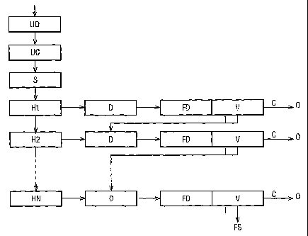
Figure 4 is a schematic diagram of the process steps performed by a receiver
in
accordance with the present invention. The received signal is demodulated by a
unique
word demodulator UD, which may be coherent or non-coherent, and is optimised
for
BPSK demodulation of the unique word signal. The demodulated unique word
symbols
are processed by a unique word correlator UC which generates a list of
possible frame
sync positions in time or hypotheses, together with a measure of their
relative strengths.
The unique word correlator may use additional rules, such as Massey's rule.
Where the unique word is variable to convey signalling information, the unique
word correlator correlates the demodulated symbols with each of the possible
unique
words and generates a strength for each possible unique word.
The possible hypotheses Hl to HN are sorted by a sorter S according to their
strengths. The hypotheses H are processed in order of their hypothesis
strength, and for
each processed hypothesis the receiver demodulates the received frame using a
demodulator D and decodes the demodulated data using an iterative FEC decoder
FD
corresponding to the FEC coder used to encode the signal. For Turbo decoding,
either
CA 02437319 2003-07-31
WO 02/062005 PCT/GB02/00431
9
the MAP or SOVA algorithms may be used by the FEC decoder FD. After each
iteration of the FEC decoding algorithm, the number of unique word errors is
compared
with the number of unique word errors detected before that iteration, by a
verification
process V. If the hypothesis is correct, as indicated by the arrow C, the
number of errors
should decrease over one or more iterations. If this is the case, the decoded
data is
output at an output stage O and the decoding step is complete for the current
frame.
If the number of unique word errors increases or stays the same after one or
more decoding iterations, the hypothesis is judged incorrect, as indicated by
the arrow I,
and the hypothesis H of the next highest strength is selected for processing.
The
hypotheses are processed in order of strength until a correct hypothesis is
found, or all
of the hypotheses have been processed without finding a correct one. In the
latter case,
the frame cannot be decoded, and is discarded at a failure stage FS.
Figure 4 shows multiple demodulating, decoding and verification steps, but
this
does not necessarily imply that there are multiple demodulators, decoders and
verifiers.
While the use of Turbo codes has been described above, other systematic and/or
convolutional codes may be used to achieve some or all of the effects of the
invention.
Although the encoding and decoding stages are illustrated in terms of discrete
processes, either of these stages may be performed by a single processor, such
as a DSP.
A computer program may be provided for execution on the processor so as to
perform
the encoding or decoding processes. The computer program may be stored on a
suitable
physical carrier, such as a disc, or transmitted on a suitable signal carrier.