Note: Descriptions are shown in the official language in which they were submitted.
CA 02437705 2003-08-05
WO 02/067018 PCT/US02/03418
AGILE MULTI-BEAM FREE-SPACE OPTICAL COMMUNICATION
APPARATUS
FIELD OF THE INVENTION
The present invention relates in general to optical
communication systems, and is particularly directed to a
new and improved, electronically agile, free-space optical
communication apparatus, that is configured to provide for
to selectively directing each of ~ plurality of independent
1,
optical beams, such as.those modulated with respectively
different communication signals, through a common optical
aperture in respectively different directions to a
plurality of spatially diverse receiver sites.
BACKGROUND OF THE INVENTION
Currently available optical (e. g., laser-based)
communication systems intended for free space applications,
such as building-to-building local area networks and trunk
2o extension systems, are customarily configured as (short
range and long range) free space 'point-to-point' systems.
As shown diagrammatically in Figures 1 and 2, such systems
typically include local and remote optical (laser-based)
transceiver pairs 1/2 and 4/5, each of which has an
associated telescope for an aperture, and are optically
coupled to one another over one or more line-of-sight
optical links 3/6.
As further shown in Figure 2, for long range
applications in excess of a few km, some form of actively
3o driven mechanical stabilization platform 7 is customarily
used to maintain beam pointing. In addition, for point-to-
point applications that are consistent with hub-spoke
operation, the systems have a highly integrated
configuration, such as that shown in Figure 3,.and require
s5 a substantial amount of hardware to provide multiple point-
to-point links between a high power hub, site 8 and a
plurality of receiver (subscriber) sites 9. Unfortunately,
1
CA 02437705 2003-08-05
WO 02/067018 PCT/US02/03418
none of these existing architectures addresses tactical
applications or mobile nodes, nor do they provide for low
cost point-to-multipoint communications.
SUMMARY OF THE INVENTION
In accordance with the present invention, advantage is
taken of recent and emerging technology developments in
free-space optical communications (FSOC), including
economically produced dense arrays of addressable
to transmitter and receiver elements, to provide an
electronically agile multi-beam optical transceiver (or
'AMOX') for use in a point-to-multipoint hub, that allows
any of multiple optical beams (independently modulated with
respectively different communication signals), to be
s5 dynamically routed and spatially re-directed, as desired,
in respectively different directions through a common
optical aperture over a relatively wide field to a
plurality of spatially diverse sites or nodes. The
invention also includes a tracking array that actively
2o corrects for pointing and tracking errors that may be due
to relative node motions and atmospheric induced
distortions. Being electronically agile, the invention has
no moving parts, and thus achieves a reduction in size,
weight, and cost, while improving reliability and
25 functionality.
To this end, a multiport input-output unit contains an
input crossbar switch, respective inputs of which are
supplied with electronic signals, such as subscriber
signals supplied by way of a digital telecommunication
3o network. The crossbar switch's outputs are connected to
respective transmitter driver circuits coupled to a (two-
dimensional) array of light emitter (laser) elements, whose
output beams are coupled to a telecentric lens system. For
an integrated transceiver application, the telecentric lens
35 system contains a frequency-selective (dichroic) interface
that allows light at the transmission wavelength generated
2
CA 02437705 2003-08-05
WO 02/067018 PCT/US02/03418
by the light emitter array to pass to and diverge from a
convex face of the lens, whereas light incident upon the
lens's convex face is reflected by the dichroic interface
to an opto-electronic receiver array.
s The telecentric lens performs a geometric transform of
a beam from a spatial location of the transmit array along
a path passing through a focal point within an aperture at
the exit face of the lens diverges in accordance with the
two-dimensional spatial displacement from the beam axis of
so its associated emitter within the transmitter array. This
means that the desired travel path of an optical beam
carrying a particular signal channel may be readily defined
by controlling the crossbar switch feeding the two-
dimensional transmitter array. Thus, the invention is able
15 to project multiple transmit optical signals from a two
dimensional planar array of optical emitters into
differentially divergent, free-space beams through a
commonly shared aperture of the telecentric lens, with a
precise relationship between the position of an emitter and
2o it's angular transmit direction.
In the receive or return path direction, the
telecentric lens accepts multiple receive optical beams and
directs them onto a two-dimensional receiver array. The
optics of the lens system produce a typical Fourier
25 transform operation, and the focal plane positions
correspond to unique angular beam directions. The
photodetector array has its outputs connected to respective
signal demodulators outputs of which are coupled to an
receiver ,side crossbar switch, outputs of which are
so supplied to digital subscriber lines coupled to the
transmit crossbar switch.
An auxiliary tracking (two-dimensional) photodetector
array may be used to monitor one or more beams from nodes
whose spatial locations relative to the hub site are
35 precisely known. Any offset in the spatial location of a
'tracking' beam from such a node on the tracking array is
3
CA 02437705 2003-08-05
WO 02/067018 PCT/US02/03418
used as an error correction signal by the control processor
to impart the appropriate (X-Y) correction, as needed, in
the steering commands supplied to the crossbar switches so
as to provide for real-time pointing/tracking and
s atmospheric correction capability.
In some applications, the transmit and receive beams
may be split between two spatially separate apertures, so
that (transmit vs. receive) wavelength segregation is not
necessary. Potential advantages of such .beam division
so include larger receiver apertures for improved signal
collection, optimization to specific transmit and receive
array configurations, and a reduction in the complexity of
diffractive optical elements or holographic optical
elements.
15 The transmitter array may be implemented in a variety
of ways. Where the number of remote nodes, which are
generally spatially stable, is small, a sub-populated
non-switchable or 'non-agile' array may be employed. An
example of a 'non-agile' application involves the use of an
2o Ethernet network to 'locally' connect buildings that are
reasonably close to one another. A limited set of discrete
laser sources may be hard-wired via an array of associated
optical fibers to respective spatial locations within a
light emitter array plane, for which the spatial-to-angular
25 transform produced by the telecentric~lens will direct the
emitter beams along angular directions to subscriber nodes.
Although the invention may be applied to such
'non-agile' multi-beam terminals, the preferred embodiment
of the invention employs the 'agile' configuration
ao described above, in which any array position is potentially
active and dynamically addressable. A non-limiting
application of an agile array would be to allow mobile
communication personnel to rapidly deploy a local area
network (LAN), while providing for dynamic variations in
35 the number and/or physical locations of the nodes of the
4
CA 02437705 2003-08-05
WO 02/067018 PCT/US02/03418
network, and to track and correct for relative motion
between the nodes.
To realize cost-effective, agile transmitter arrays,
vertical cavity surface-emitting laser (VCSEL) components
may be employed in combination with an MxN digital crossbar
switch. Alternatively, the VCSELs may be replaced by
discrete laser diodes in a sub-populated array. An
advantage of VCSELs is their ability to simultaneously emit
multiple transverse modes (MTMs). A mufti-transverse mode
to source may reduce the effects of atmospheric scintillation
in a FSOC link. With an MTM source, the beam is already
somewhat homogenized, so that additional phase scrambling
due to scintillation may be greatly reduced. This effect
may also be generated or enhanced by using a custom-
designed optical element to scramble the phase-fronts prior
to transmission. As a non-limiting example, a DOE/HOE or a
simple diffuser may be employed. This technique may also be
used to produce the desired beam angle for the intended
application.
2o As an alternative to electronic configurations, each
crossbar switch may be implemented as an all-optical fiber
optic switch. A principal advantage of an optical fiber
approach is that the number of laser elements can be
reduced to match the number of input signals. The transmit
element array may comprise a fully populated fiber optic
bundle, which can be configured and sized to have the
desired element center-to-center spacing.
Although the transmitter array may comprise a
spatially periodic, two-dimensional array of point-source
3o emitters, the beams impinging upon the receiver array can
be expected to be incident at arbitrary locations within
the array depending on the angular position of subscriber
nodes. The receiver array elements should therefore have
the largest possible active area (up to the desired spatial
resolution of the array) and the highest possible
fill-factor' (or very little dead space between
5
CA 02437705 2003-08-05
WO 02/067018 PCT/US02/03418
photodetector elements). Also, the node connecting the
detector, preamplifier, and feedback resistor components of
a respective photodetector element must be relatively
'physically short' in order to preserve the receiver's
bandwidth performance. In a two-dimensional receiver array,
this node length may become unacceptable due to the loss of
the second dimension for mounting components. The receiver
array may be configured as a fiber bundle outputs of which
are (optical-fiber) routed via a set of fiber optic
' to switches to a subset of optimized discrete photodetectors.
BRIEF DESCRIPTION OF THE DRAWINGS
Figure 1 diagrammatically illustrates a conventional
short range, free space optical laser-based) communication
s5 system;
Figure 2 diagrammatically illustrates a conventional
long range, free space optical laser-based) communication
system;
Figure 3 diagrammatically illustrates hub/spoke
2o configured multiple point-to-point free space optical
communication system;
Figure 4 diagrammatically illustrates an
(electronically) agile multi-beam optical transceiver in
accordance with the invention;
25 Figure 5 shows an example of a telecentric lens
configuration that may be used in the transceiver of Figure
4;
Figure 6 depicts a telecentric lens configuration for
a unidirectional terminal;
3o Figure 7 is a beam-forming geometry diagram associated
with a common aperture;
Figure 8 diagrammatically illustrates a non-agile
multi-beam optical transmitter for electrical input
signals;
6
CA 02437705 2003-08-05
WO 02/067018 PCT/US02/03418
Figure 9 diagrammatically illustrates a non-agile
multi-beam optical transmitter for fiber optic input
signals;
Figure 10 shows an electronically agile transmitter
array employing vertical cavity surface-emitting lasers
coupled with a crossbar switch;
Figure 11 shows an electronically agile transmitter
array employing discrete laser diodes in a sub-populated
array coupled with a crossbar switch;
1o Figures 12 and 13 show respective transmitter arrays
employing a fiber optic crossbar switch;
Figure 14 shows an. example of compiled results of link
analyses for determining array size and addressable
field-of-regard; and
is Figure 15 shows an alternative embodiment of a
receiver array.
DETAILED DESCRIPTION
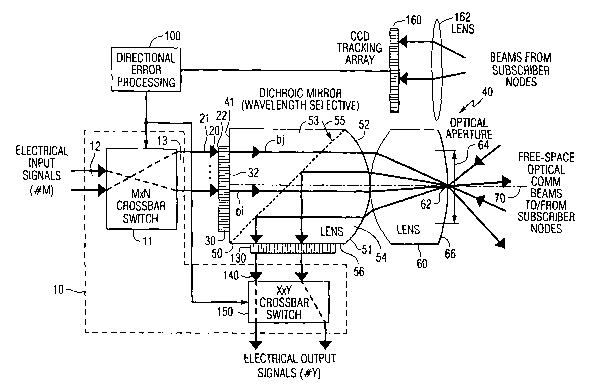
A non-limiting embodiment of the multi-beam
2o communication apparatus in accordance with the present
invention, configured as. an (electronically) agile
multi-beam optical transceiver (AMOX) for use in a point
to-multipoint hub, is diagrammatically illustrated in
Figure 4 as comprising a multiport input-output unit shown
25 in broken lines 10, that is coupled to receive electronic
signals, such as those provided by way of a variety of
signal transport paths, including (subscriber) signals
supplied.by way of a digital telecommunication network. As
a non-limiting example, in the transmit direction, the
3o input-output unit 10 may include an M input by N output
crossbar switch 11 of the type typically installed as part
of a telecommunication service provider's central office
equipment.
The crossbar switch 11 serves to enable a signal
35 applied to any input port of an array of M input ports 12
to be controllably electronically steered (by an associated
7
CA 02437705 2003-08-05
WO 02/067018 PCT/US02/03418
control processor 100) to any output port of an array of N
output ports 13. The N output ports 13 of the switch 11 are
connected, in turn, to respective signal inputs 21 of a set
of transmitter driver circuits 20, outputs 22 of which are
s coupled to signal inputs of an integrated array of light
emitter elements 30. While the light emitter array 30 may
comprise a 1xK array of elements, in a preferred embodiment
for expanded volume multipoint transmission coverage, the
light emitter array 30 is configured as a two-dimensional
to spatially array of light emitting elements (e. g., lasers),
output beams of which have a prescribed optical
'transmission wavelength 7~,.' As a non-limiting example,
array 30 may comprise a laser emitter array available from
Novalux Inc., Sunnyvale, California, having a substantially
15 planar output surface 32, which facilitates intimately
optically coupling the array with a substantially planar
input face 41 of a telecentric lens system 40.
The telecentric lens system 40 may comprise a first
lens element 50 having a first, substantially planar face
20 51 and a second, convex face 52 that is optically coupled
with an adjoining second, convex-convex optical beam
translating lens element 60. For the case of a two-
dimensional light emitter array, the geometrical surfaces
of the lens elements of the telecentric lens, that are
25 intersected by an axis 70 orthogonal to the center of the
laser element array 30, are surfaces of revolution,
symmetric about the axis 70.
For the present transceiver example, the lens element
50 may be formed by bonding first and second lens block
ao components 53 and 54 to a frequency-selective (dichroic)
interface 55, that allows light at the transmission
~ wavelength 7~,I, generated by the light emitter element array
30 to pass through the interface 55 and exit the second,
convex face 52, whereas light having a different receiver
35 wavelength ~ as received by the face 52 from the lens
element 60 is reflected by the lens' dichroic interface 55
8
CA 02437705 2003-08-05
WO 02/067018 PCT/US02/03418
towards a side face 56, to which an opto-electronic
receiver array 130 is coupled. The receiver array
preferably includes a front end normal-incidence bandpass
filter. This filter, in conjunction with the wavelength
selective dichroic mirror in the telecentric lens
arrangement, is effective to efficiently filter background
light from the received signals.
In an alternative configuration, the lens element 50
may be implemented as two sub-components, as shown at 80
to and 90 in Figure 5 (which illustrate transmit and receive
beams associated with three duplex channels). In the
telecentric lens configuration of Figure 5, the first sub-
lens component 80 is formed of two bonded components with a
dichroic interface 55 therebetween, as in the architecture
s5 of Figure 4. The sub-lens component 80 has a first
substantially planar face 81 to which the light emitter
array 30 is coupled, and a second planar face 82 that
adjoins an associated planar face 91 of the second sub-lens
component 90. The sub-lens component 90 has a convex face
20 92 that is optically coupled with the adjoining convex-
convex optical beam translating lens element 60.
As shown in Figure 4, the telecentric lens arrangement
40 is effective to perform a geometric transform of an
optical beam incident upon the generally planar surface 51
25 of the lens element 50, along a path passing through and
diverging from a focal point 62 within an aperture 64 at
the exit face 66 of the lens element 60. As shown in Figure
5, the parameters of the lens system are such that the
diameter of the aperture 64 is sufficient to accommodate
3o spreading of each of the transmit beams from its respective
emitter within the array 30. The transmit beams (having
transmission wavelength 7~"h) are de-focused to the desired
amount of angular beam width by simply controlling the
distance between the surface 51 to which the array 30 is
35 coupled and the telecentric lens. This does not impact the
steering direction of the beams.
9
CA 02437705 2003-08-05
WO 02/067018 PCT/US02/03418
The geometric transform performed by the telecentric
lens is such that the angle a subtended by the travel path
of a beam exiting the exit face 66 of the lens element 60,
and diverging from the central beam axis 70 (which passes
through the telecentric lens' focal point 62) is definable
in accordance with the two-dimensional spatial displacement
from the beam axis 70 of its associated emitter within the
array 30. Thus, as shown in Figure 4, a beam bi generated
by a laser emitter within the array 30 that is relatively
to close to the axis 70 will undergo a smaller angle of
divergence through the focal point 62 from the axis 70,
than will a beam b~ generated by a laser emitter that
spaced farther away from the axis.
This means that the desired travel path of an optical
beam carrying a particular signal channel may be readily
defined by controlling the crossbar switch 11 feeding the
two-dimensional light beam element array 30, so as to steer
the signal from whichever one of the switch's input ports
12 to which it is applied, to that one of the switch output
2o ports 13 whose associated light beam element in the light
element array 30 produces the intended travel path - based
upon the geometry parameters of the spatial separation-to-
angular divergence transform, described above.
Namely, the invention is able to project multiple
transmit optical signals from a two-dimensional planar
array of optical emitters into differentially divergent,
free-space beams through a commonly shared aperture of the
telecentric lens, with a precise relationship between the
position of an emitter and it's angular transmit direction.
3o Conversely, in the receive or return path direction, the
telecentric lens accepts multiple receive optical beams and
directs them onto a two-dimensional receiver array. The
optics of the lens system produce a typical Fourier
transform operation, and the focal plane positions
correspond to unique angular beam directions.
CA 02437705 2003-08-05
WO 02/067018 PCT/US02/03418
The received beams at a prescribed optical receiver
wavelength 7~,R, are preferably defocused, so that their
spots on an opto-electronic receiver array 130 are
appropriately larger than any dead spaces of the array.
This defocusing obviates the requirement for
diffraction-limited optical performance, so that lens
components 90 and 60 may be implemented as a pair of simple
spherical lenses.
As pointed out briefly above, for the point-to
so multipoint transceiver application of the present example,
the dichroic material-coated interface 55 of lens element
50 reflects light received by face 52 from the lens element
60 toward the side face 56, to which an opto-electronic
receiver array 130 is coupled. As in the case of the
s5 transmitter array 30, although the light receiver array 130
may comprise a linear (1xJ) array of photodetector
elements, it is preferably configured as a two-dimensional
array of photodetector elements, having a sensitivity
characteristic at optical receiver wavelength ?~, different
2o from the optical transmission wavelength ~"L.
As a non-limiting example, the photodetector array 130
may comprise a photodetector array from Sensors Unlimited
Inc., Princeton N.J., having a substantially planar input
surface 132, to facilitate intimately optically coupling
25 the array with the substantially planar side surface 56 of
the lens element 50. Where the transceiver application
provides duplex communications with each remote site, the
photodetector array 130 may have effectively the same size
as the laser emitter array 30, so that its photodetector
so elements are readily aligned with the input beams directed
thereon from the remote sites by the telecentric lens.
The photodetector array 130 has its signal output
ports connected to respective signal inputs of a set of
receiver demodulators 140, outputs of which are coupled to
35 signal inputs of an X input by Y output crossbar switch
150. The output crossbar switch 150 may be configured
11
CA 02437705 2003-08-05
WO 02/067018 PCT/US02/03418
complementary to the input crossbar switch 11, so that X=N
and Y=M. As such, the output signals from the output
crossbar switch 150 may be supplied to digital subscriber
lines coupled to the transmit side crossbar switch 11 for
s the case of duplex communications. In a complementary sense
to the transmit crossbar switch 11, the receiver crossbar
switch 150 serves to enable a signal applied to any of X=N
input ports 151 from the receiver demodulator circuitry 140
to be controllably electronically steered to any of its Y=M
to output ports.
Also shown in Figure 4 is an auxiliary tracking (two-
dimensional) photodetector array 160 coupled with an
associated focusing lens 162. Array 160 may comprise a
conventional charge-coupled device (CCD) receiver array.
i5 The outputs of the tracking array 160 are coupled to the
control processor 100, which defines the spatial steering
of the signal beams through its control of the crossbar
switches 30 and 130, as described above. The auxiliary
array 160 is used to monitor one or more beams from nodes
2o whose spatial locations relative to the hub site are
precisely known a priori. Any offset in the spatial
location of a 'tracking' beam from such a node on the
tracking array 160 is used as an error correction signal by
the control processor to impart the appropriate (X-Y)
25 correction, as needed, in the steering commands supplied by
the control processor 100 to the crossbar switches 30 and
130, so as to provide for real-time pointing/tracking and
atmospheric correction capability.
While the optical transceiver embodiment shown in
3o Figures 4 and 5 may employ conventional spherical lenses,
as described above, it should be realized that there may be
significant cost and performance advantages in using other
components, such as diffractive optical elements (DOES) or
holographic optical elements (HOES), it being understood
35 that the wavelength-dependent aspects of such elements must
12
CA 02437705 2003-08-05
WO 02/067018 PCT/US02/03418
be taken into account in the course of configuring a two-
wavelength transceiver system.
Also, although the AMOX architecture described above
allows all of the transmit and receive beams to share a
common aperture, this is not a functional necessity. In
certain applications, it may be advantageous to split the
transmit and receive beams between two spatially separate
apertures, so that (transmit vs.° receive) wavelength
segregation employed in the embodiment of Figures 4 and 5
so is not necessary. Potential advantages of such beam
division include larger receiver apertures for improved
signal collection, optimization to specific transmit and
receive array configurations, and a reduction in the
complexity of DOE/HOE's optical elements (where
applicable) .
As shown in Figure 6, an optical configuration for
such a unidirectional terminal is similar to that shown in
Figure 5, except for the absence of a dichroic beam
splitter, for a respective transmit or receive portion of
2o an AMOX architecture. Here, the terminal serves as an
adaptive multi-beam optical transmitter (AMOT) or an
adaptive multi-beam optical receiver (AMOR). Whether
implementing an AMOX, AMOT, or AMOR, the components of the
optical system can be readily scaled to specific arrays and
beam-forming requirements. A significant amount of
flexibility is therefore available to accommodate a wide
range of system applications including interdependent
variations in field-of-regard (FOR), data rates, link
ranges, etc.
3o Regardless of whether an integrated transit/receive
embodiment or a segregated transmit and receive embodiment
is employed, the beams share a common aperture, so that
there is a contiguous near-field beam coverage over the
full FOR. In addition, as shown in the beam-forming
geometry diagram of Figure 7, where the angle Oi between
adjacent transmitted beams is no more than the angular beam
13
CA 02437705 2003-08-05
WO 02/067018 PCT/US02/03418
width Od between (for example -3 dB beam edges), there will
be a contiguous beam coverage in the far-field as well. The
most efficient use of beam space occurs with Oi - Od. In
this case, neighboring beams become "resolvable" (e. g.,
centerlines are separated by one-half a beamwidth) at a
distance of Ls = Dt/tan0l.
Transmitter arrays for the above-described FSOC
terminal may be implemented in a variety of ways. In a
relatively simple application having only a small number of
io remote nodes, which are also generally spatially stable,
sub-populated non-switchable arrays may be employed. A
principal example of such a 'non-agile' application
involves the use of an Ethernet network to 'locally'
connect buildings that are in reasonably close proximity to
one another.
For such an application, a relatively limited set of
discrete laser sources 191 are coupled to receive
electrical input signals in the embodiment of Figure 8 and
optical input signals 196 to laser amplifiers 195 in the
2o embodiment of Figure 9. The outputs of the lasers may be
hard-wired via an array of associated optical fibers 192 to
respective spatial locations 193 within a light emitter
array plane 194, for which the spatial-to-angular transform
produced by the telecentric lens will direct the emitter
beams along the desired angular directions of the
subscriber nodes. A benefit of the fiber optic input
embodiment of Figure 9 is the fact that a respective input
signal may require only optical amplification prior to
being transmitting into free space. Optionally, the fiber
optic array may comprise a fully populated fiber bundle, in
which only specific fibers are connected to laser sources
based on subscriber demand. In either case, M input data
channels are specifically mapped to M output beam
directions, as shown.
Although the invention may be applied to such
'non-agile' multi-beam terminals, the preferred embodiment
14
CA 02437705 2003-08-05
WO 02/067018 PCT/US02/03418
of the invention employs the 'agile' configuration
described above with reference to Figures 4-7, in which any
array position is potentially active and dynamically
addressable. A non-limiting application of an agile array
would be to allow mobile communication. personnel to rapidly
deploy a local area network (LAN), while providing for
dynamic variations in the number and/or physical locations
of the nodes of the network, and to track and correct for
relative motion between the nodes.
to In order to realize cost-effective, agile transmitter
arrays, vertical cavity surface-emitting laser (VCSEL)
components may be as the array 30 in. combination with an
MxN digital crossbar switch, as diagrammatically
illustrated in the architecture of Figure 10.
Alternatively, as shown in the embodiment of Figure 11, the
VCSELs may be replaced by discrete laser diodes 191 in a
sub-populated array, similar to the embodiment of Figure 8.
An advantage of using VCSELs is their ability to
simultaneously emit multiple transverse modes. For reasons
2o similar to the ability of a light-emitting diode (LED) to
eliminate modal noise in a mufti-mode fiber link, a
mufti-transverse mode (MTM) source may also significantly
reduce the effects of atmospheric scintillation in a FSOC
link.
Scintillation is the result of mufti-path propagation
in the atmosphere due to inhomogeneities in the index of
refraction of air, causing the beam to temporally interfere
with itself, both constructively and destructively. With an
MTM source, however, the beam has already been somewhat
"pre-scrambled" or homogenized, so the effects of
additional phase scrambling due to scintillation may be
greatly reduced, in comparison with problems that can occur
with a single-transverse-mode source. This effect may also
be generated or enhanced by using a custom-designed optical
element to scramble the phase-fronts prior to transmission.
As a non-limiting example, a DOE/HOE or a simple diffuser
CA 02437705 2003-08-05
WO 02/067018 PCT/US02/03418
may be employed. This technique may also be used to produce
the desired beam angle for the intended application,
thereby efficiently accomplishing both objectives.
The MxN digital crossbar switches described above may
be implemented in a variety of ways, such as, but not
limited to application specific integrated circuits
(ASICs), and logically controlled high-speed switches
(LCHSSs). An ASIC implementation has several significant
technical advantages, including very high packaging density
so (only one chip), reliability, and lower power requirements.
However, in small quantities, ASICs may not be practical,
due to their high set-up costs and the long continuing
backlog at ASIC foundries. The LCHSS approach interconnects
several high-speed digital switches to route the data
z5 signals and a field programmable,gate array (FPGA), to
control the configuration of the switches. This
implementation is relatively low cost and can be packaged
in a small volume.
The electrical bias of the laser emitters of the
2o transmit array must also be individually controlled to
maintain overall low power operation and to reduce the
effects of heat buildup. For example, if a maximum of ten
simultaneous transmit beams is employed, the emitters can
be controlled with ten current sources, that are switched
25 to the lasers via semiconductor switches and controlled by
the same FPGA used to control the data switches.
Alternatively, the crossbar switch may be implemented
as an all-optical fiber optic switch, as diagrammatically
illustrated at 120 in Figures 12 and 13. A principal
3o advantage of an optical fiber approach is that the number
of laser elements 191 (e. g., lasers having a transmit
wavelength of 1550 nm) can be reduced to match the number
of input signals. In the embodiments of Figure 12 and 13, a
transmit element array 123 is formed of a fully populated
3s fiber optic bundle, which can be configured and sized to
have the desired element center-to-center spacing.
16
CA 02437705 2003-08-05
WO 02/067018 PCT/US02/03418
Consistent with point-to-multipoint (PMP)
applications, preliminary link analyses have been performed
to explore inter-related issues of data rate, link range,
beam width, number of array elements, optical power,
addressable field-of-regard (FOR), background optical
noise, etc. The subscriber nodes in the PMP network are
assumed to be single-channel (i.e., single laser, single
detector). As such, they may employ collection apertures
and transmit beam widths consistent with closing a duplex
to link with the multi-channel hub terminal in a conventional
manner. As a non-limiting example, a fixed subscriber
collection aperture of 6.0 inches may be assumed.
Figure 14 shows an example of compiling the results of
many link analyses to determine array size (number of
required emitters) and addressable field-of-regard (FOR).
In particular, Figure 14 illustrates the number of array
emitters required to cover FOR's ranging between 30° and
90° at data rates of 39 and 622 Mbps. For instance, to
operate at a range of 1 km, a data rate of 622 Mbps, and a
2o FOR of 30°x90°, the transmit array requires on the order of
20x60 emitter elements.
The receiver array generally requires a more
complicated implementation than the transmitter array.
Although, as described above, the transmitter array may
comprise a spatially periodic, two-dimensional array of
point-source emitters, the beams impinging upon the
receiver array can be expected to be incident at arbitrary
locations within the array depending on the angular
position of subscriber nodes. The receiver array elements
3o should therefore have the largest possible active area (up
to the desired spatial resolution of the array) and the
highest possible fill-factor (or very little dead space
between photodetector elements).
In addition, the node connecting the detector,
preamplifier, and feedback resistor components of a
respective photodetector element must be relatively
17
CA 02437705 2003-08-05
WO 02/067018 PCT/US02/03418
'physically short' in order to preserve the receiver's
bandwidth performance. In a two-dimensional receiver array,
this node length may become unacceptable due to the loss of
the second dimension for mounting components. To obviate
this problem the detector's preamplifier may be co-mounted
on the detector substrate. Alternatively, the receiver
array may be configured as diagrammatically illustrated in
Figure 15, which shows the collection of the received beams
on the end of a fiber bundle 125, the outputs of which are
to (optical-fiber) routed via a set of fiber optic switches
120 to a subset of optimized discrete photodetectors 127.
This receiver architecture of Figure 15 is essentially
the inverse of the transmit array architecture of Figure
12, described above. In order, to achieve a high
fill-factor, a respective optical fiber may contain a
multimode core with a relatively thin cladding layer, such
as a 100/125 micron core/cladding diameter. A 100 micron
core provides a relatively good match to the active area of
a high-performance photodetector operating in excess of 1
2o Gbps. The fibers from the bundle 221 can be physically
'fanned', as necessary, in order to interface with the
fiber optic switch 223. High-density packaging of the
receiver modules 223 can be enhanced by using integrated
receiver arrays, which are currently commercially available
in packages of up to 1x16 on a single substrate.
As will be appreciated from the foregoing description,
the present invention takes advantage of current and
emerging technology developments in free-space optical
communications, to realize an electronically agile
3o multi-beam optical transceiver for use in a point-to-
multipoint hub. This agile transceiver allows any of
multiple optical beams to be dynamically routed and
spatially re-directed, in respectively different directions
through a common optical aperture over a relatively wide
s5 field to a plurality of spatially diverse sites or nodes.
Tn addition, a tracking array actively corrects for
18
CA 02437705 2003-08-05
WO 02/067018 PCT/US02/03418
pointing and tracking errors that may be due to relative
node motions and atmospheric induced distortions. Having no
moving parts, the invention provides a reduction in size,
weight, and cost, while improving reliability and
s functionality.
While we have shown and described several embodiments
in accordance with the present invention, it is to be
understood that the same is not limited thereto but is
susceptible to numerous changes and modifications as known
~.o to a person skilled in the art. We therefore do not wish to
be limited to the details shown and described herein, but
intend to cover all such changes and modifications as are
obvious to one of ordinary skill in the art.
I9