Note: Descriptions are shown in the official language in which they were submitted.
CA 02437833 2003-06-25
WO 02/057698 PCT/FI02/00001
METHOD AND APPARATUS FOR FEEDING A STACK OF METALLIC
SHEETS INTO A MELTING FURNACE
This invention relates to a method for feeding stacks of metal into a melting
s furnace described in the preamble of claim 1. The invention also relates to
the
apparatus described in the preamble to claim 5.
Production methods are used in the manufacture of metals where, at certain
stages, stacks of metallic sheets are fed into a melting furnace. For
instance,
io these could be stacks of cathodes, such as zinc cathode sheet stacks
separated from the permanent cathode by the stripping machine, which are
melted in the melting furnace and cast into castings, e.g. into castings
easier to
transport, such as blocks.
is Methods and apparatus are known whereby metallic cathode stacks arranged
on a conveyor are dropped straight from the melting furnace feed inlet into
the
.F.
furnace. Metallic cathode stacks dropped thus from relatively high have
exposed parts of the furnace, such as the lining and inductors, to being hit
and
to damage caused by this. fn addition, dropping the stacks from a height has
2o harmful effects on the temperature of the melt in the furnace, which should
remain stable. These factors have been detrimental to the service life of the
furnace parts.
The purpose of this invention is to obtain a method and apparatus that will
help
2s avoid the drawbacks of the prior art.
The characteristics of the invention are made apparent in the patent claims.
The method and apparatus of the present invention have many significant
advantages. Lowering the stacks ~of cathodes into the furnace chamber
relatively near the bottom of the furnace avoids strong blows to the furnace
parts. Furthermore, lowering the cathodes into the melt slowly avoids great
CA 02437833 2003-06-25
WO 02/057698 PCT/FI02/00001
2
changes in temperature. The apparatus of the invention, with which the
cathode stacks are lowered into the furnace chamber, avoids the use of
complicated actuators with its grapple mechanism structure, so that the
grapple
is long-lasting and reliable in the conditions prevailing inside the furnace
s chamber.
There follows a more detailed description of the invention using an example,
with reference to the attached drawings, where
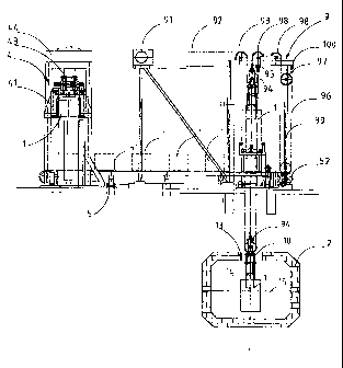
io Figure 1 presents an embodiment of the invention seen from the side,
Figure 2 shows the apparatus in Figure 1 from above,
Figure 3 presents a detailed view of the gripping stage of a metallic sheet
stack
is at the line III - III in Fig. 1, and
Figure 4 shows the transfer stage of the metallic sheet stack.
The drawings show a certain embodiment of the invention, where metallic sheet
2o stacks 1 are fed into a melting furnace 2. The metallic sheet stacks 1,
such as
cathode stacks in particular, are shown in Figure 1 in simplified form. The
apparatus shown in the drawings comprises at least one loading station 3, to
which the metallic sheets are brought for instance by forklift. At the loading
station 3 the metallic sheets are stacked one on top of another into a pile,
from
zs which the first transfer device 4, preferably a transfer elevator,
separates a
dimensioned stack 1 and conveys it to a stack conveyor 5. The stack conveyor
5, for example a chain conveyor, on which the metallic sheet stack is placed
on
top of continuous chains 6, moves the stack 1 to the turning station 7. At the
turning station 7 the stack of sheets is turned from a horizontal position,
where
3o the metallic sheets were on top of each other, to a vertical position. The
rotation
is thus preferably about 90 degrees. The turning device of the turning station
7
also includes a movable back stop 8, with which the stack of sheets 1 is
CA 02437833 2003-06-25
WO 02/057698 PCT/FI02/00001
3
pressed tight. The grapple 10 of a second transfer device 9 grips the vertical
stack of sheets 1. The clamping elements 11, 12 of the grapple press against
the outer sheets on opposite edges of the stack and lift the stack of sheets
from
the turning device 7 and transfer the stack 1 from the feed inlet 13 of the
s melting furnace 2 into the furnace chamber 14. The stack of sheets is
lowered
inside the furnace preferably at least partially below the surface of the melt
15,
whereupon the grapple 10 opens and the stack is released from the grip of the
grapple 10 to remain in the furnace chamber 14. The grapple 10 is preferably
arranged to open at a regulated standard height inside the furnace chamber
14..
to The grapple is raised out of the furnace chamber to take the next stack
from
the turning device.
In the method of the invention, in order to transfer stacks of metallic
sheets, in
particular stacks of metallic cathodes, to the melting furnace, the stack of
is metallic sheets 1 is gripped by a grapple element 10, such as a lifting
grapple,
which is fixed on a transfer device, and the stack of metallic sheets 1 is
moved
into the melting furnace 2 chamber 14, and at a predetermined height inside
the
furnace chamber, preferably relatively near the bottom of the furnace and/or
melt, the metallic stack 1 is released. The stack of metallic sheets 1 is
gripped
2o by the grapple device 10 by the opposite walls of the stack of sheets. The
stack
of metallic sheets 1 is turned to a vertical position before the grapple
element
grips it. The stack of metallic sheets 1 is released by acting on the grapple
element 10 with a mechanical arrangement.
2s The apparatus according to the invention for conveying stacks of metallic
sheets 1, in particular metallic cathode stacks, to a melting furnace 2
comprises
a lifting device 9 and a grapple device 10 fixed to it and elements arranged
on
the grapple for the release of the stack of metallic sheets 1 into the chamber
14
of a melting furnace 2 at a predetermined height. The grapple device 10
3o consists of a grapple frame 18, which is arranged movably on a lifting
frame 19,
and clamp elements 11, 12 hinged scissor-like to the grapple frame, and
attached in a hinged way at the upper ends to the lifting frame 19 by means of
CA 02437833 2003-06-25
WO 02/057698 PCT/FI02/00001
4
support arms 16, 17 so that when the grapple frame 18 moves downwards in
relation to the lifting frame 19, the clamp elements 11, 12 move into the
clamping position and that when the grapple frame 18 moves upwards with
regard to the lifting frame 19, the clamp elements 11, 12 move towards the
s open position. The grapple frame 18 stop element 96, in particular a stop
cable, is set to the grapple 10 connection, which at a certain predetermined
point prevents the movement of the grapple frame 18 with the lifting frame 19
when lowering the stack of metallic sheets 1 into the furnace chamber 14, so
that the grapple frame in relation to the lifting frame 19 begins to move
io upwards, whereupon the clamp elements 11, 12 move towards the open
position. The grapple device also comprises locking elements 20, 21 for
locking
the clamp elements 11, 12 at least in the open position and an element 22 for
removing the locking of the clamp element. In addition the equipment
comprises at least one loading station 3, a feeding device 4 for detaching the
is stacks of metallic sheets 1 in the loading station at a standard height and
for
conveying the stacks of sheets to a conveying device 5, a conveying device 5
for transferring the stacks of metallic sheets 1 to the sheet stack turning
station
7 and appliances on the turning station for turning the stacks of metallic
sheets
1 into an upright position. The stop cable acting as a grapple frame stop
2o element on the grapple device is fixed by its first end to the grapple
frame and
at the other end to the frame structure 100 and arranged so as to move via at
least two bending wheels 97, 98, of which at least one bending wheel 97 is
attached movably to its guide 99.
2s The equipment according to the invention, in particular the transfer device
9,
with which the stack of metallic sheets 1 that have been turned upright is
moved from the turning device to the furnace 2 comprises therefore a lifting
device. The drive mechanism 91 of the lifting device comprises a vrrinding
drum
and appliances for operating the winding drum as well as a hoist rope 92 or
the
30 like, which is preferably a lifting cable. From the winding drum the hoist
rope 92
is routed via the first bending wheel 93 and via the second bending wheel 94
on
the grapple 10 connection to the fixing point 95 on the frame of the transfer
CA 02437833 2003-06-25
WO 02/057698 PCT/FI02/00001
device, to which the hoist rope 93 is attached at one end. Thus using the
winding drum of the lifting device the grapple 10 is raised or lowered
depending
on which direction the winding drum is turned. The mechanism connected to
the grapple 10 is described in more detail in Figure 3. The grapple consists
of
s clamp elements 11, 12, which are attached in scissor-like fashion to turn on
the
grapple frame 18. Clamp elements 11, 12 are attached in a hinged way at their
upper end to support arms 16, 17, which for their part are attached in a
hinged
way at their upper ends to the lifting frame 19. The grapple frame 18 is
attached
movably to the lifting frame 19, preferably to move in essence vertically.
When
io the grapple frame 18 is in the lower position, the~clamps 11, 12 hold the
stack
of metallic sheets 1 in the clamped position and correspondingly when the
grapple frame 18 is in the upper position, the clamps 11, 12 are in the open
position (Fig. 3). In the equipment shown in the drawings there is a stop
element 96, typically a stop cable element or the like, preferably a stop
cable,
is arranged on the frame 18 of the grapple 10, which arrests the downward
movement of the grapple frame 18 chamber at a certain pre-regulated height in
the furnace. Thus the lifting frame 19 may be lowered further in relation to
the
grapple frame, whereby the clamps 11, 12 are forced by the support arms 16,
17 to move towards the open position. The regulated height can be determined
2o for instance by adjusting the length of the stop cable element 96. In the
case
illustrated in Figure 2, a mechanism is arranged on the stop cable element 96
connection, which comprises several bending wheels 97, 98, via which the stop
cable 96 is arranged to move. The arrangement consists of one bending wheel
97 arranged to move in guide 99, in which bending wheel stop cable 96 is
2s arranged to move. When the grapple 10 is lowered towards the furnace 2 the
bending wheel 97 is raised inside the guide 99. When the bending wheel 97 is
at its top position the stop cable element 96 stops the grapple frame 18.
When the clamps 11, 12 have opened sufficiently the locking element 20
3o arranged on their connection locks the clamps 11, 12 in the open position.
In
the embodiment shown in the drawings the locking element 20 is a clip
element, which is hinged at one end to the first clamp 11 and the clip at the
CA 02437833 2003-06-25
WO 02/057698 PCT/FI02/00001
6
other end is arranged so as to lock onto a counter element 21 arranged on the
other clamp 12. In the locked position the locking element 20 also prevents
the
grapple frame 18 from moving in relation to the lifting frame 19. The locking
element 20 opens only when the grapple 10 is lowered to take a new stack 1,
s as the back stop 22 arranged on the locking element 20 touches the upper
part
of the stack 1.
A grapple is shown in Figures 3 and 4 in two positions. In the open position
(Fig. 3) the grapple 10 is taking a stack of sheets 1 from the turning device.
In
to this position the locking element back stop is only just touching the upper
surface of the stack, and the locking element has not yet released the clamps.
In the other position (Fig. 4) the grapple is shown in the lifting position,
when
the stack of metallic sheets 1 is between the clamps 11, 12. The lifting
device is
omitted from Figure 3 for reasons of clarity.
is
The equipment described in Figures 1 and 2 thus also include the first
conveying device 4, preferably a transfer elevator, of which the grapple
element
41 separates a dimensioned stack 1 from the pile of metallic sheets at the
loading station 3, and conveys it to the stack conveyor 5. The transfer
elevator
20 4 is arranged so as to move along a track 42 transverse to the stack
conveyor,
where said track extends to the stack conveyor 5 and at least one loading
station 3. In the embodiment shown there are two loading stations 3, between
which there is a stack conveyor feed end 6. The grapple element 41 is
typically
equipped to move with lifting elements 43, such as hoist cables. The lifting
2s elements 43 are moved using drive equipment 44, such as a winding drum and
its drive mechanism.
The stack conveyor 5 comprises a conveyor element 51, such as at least one
chain conveyor, which is arranged to convey the stacks of metallic sheets 1
set
3o upon it to the turning station 7. The conveyor element 51 is moved by a
drive
mechanism 52, such as a drive wheel.
CA 02437833 2003-06-25
WO 02/057698 PCT/FI02/00001
7
Figure 3 also shows the turning device of the sheet stack 1 turning station 7
in
more detail. The turning device comprises a frame 71, on which appliances are
arranged for supporting the sheet stack at least during the turning movement.
In addition, the turning device includes preferably also a movable back stop 8
to
s press the stack of sheets tighter together at least before the grapple 10
grips
the stack 1. The back stop 8 is moved using a back stop drive mechanism 81,
such as a compression cylinder. The turning device frame 71 is hinged to turn
typically around a shaft 72 that is in the same direction as the stack
conveyor 5.
The turning device comprises in addition a rotating element 73, typically a
to compression cylinder. In the drawing the turning device is shown in two
positions, the position before turning and the turned position.
It will be clear to experts in the field that the location of different
equipment and
the directions in which they move or turn vary according to the requirements
set
is by the forms of the application. The method and equipment of the invention
are
extremely suitable for conveying for example stacks of metallic cathode
sheets,
such as stacks of zinc sheets, into a melting furnace.