Language selection

Search

Patent 2437941 Summary

Third-party information liability

Some of the information on this Web page has been provided by external sources. The Government of Canada is not responsible for the accuracy, reliability or currency of the information supplied by external sources. Users wishing to rely upon this information should consult directly with the source of the information. Content provided by external sources is not subject to official languages, privacy and accessibility requirements.

Claims and Abstract availability

Any discrepancies in the text and image of the Claims and Abstract are due to differing posting times. Text of the Claims and Abstract are posted:

  • At the time the application is open to public inspection;
  • At the time of issue of the patent (grant).
(12) Patent: (11) CA 2437941
(54) English Title: TILLAGE SWEEP
(54) French Title: SOC BINEUR POUR LE TRAVAIL DU SOL
Status: Term Expired - Post Grant Beyond Limit
Bibliographic Data
(51) International Patent Classification (IPC):
  • A01B 19/00 (2006.01)
  • A01B 35/02 (2006.01)
  • A01B 35/22 (2006.01)
  • A01B 39/02 (2006.01)
(72) Inventors :
  • POUTRE, BENOIT JOCELYN (United States of America)
(73) Owners :
  • DEERE & COMPANY
(71) Applicants :
  • DEERE & COMPANY (United States of America)
(74) Agent: BORDEN LADNER GERVAIS LLP
(74) Associate agent:
(45) Issued: 2007-02-13
(22) Filed Date: 2003-08-20
(41) Open to Public Inspection: 2004-03-13
Examination requested: 2003-08-20
Availability of licence: N/A
Dedicated to the Public: N/A
(25) Language of filing: English

Patent Cooperation Treaty (PCT): No

(30) Application Priority Data:
Application No. Country/Territory Date
10/244,299 (United States of America) 2002-09-13

Abstracts

English Abstract

A tillage sweep includes an elongated nose portion having forward cutting edges which are straight and diverge at an angle of approximately 45 degrees from a leading point. The top of the nose viewed from the side is straight and angles upwardly at an angle of approximately eleven degrees from the planar bottom surface to a juncture with a stem or connecting portion which forms an angle of about 46 degrees with the plane of the bottom surface. The sweep includes outer wing portions with leading cutting edges which are straight and which diverge at an angle of approximately 67 degrees thereby forming an angle of about 11 degrees with the respective forward cutting edges. The overall length of the sweep is greater than the width.


French Abstract

Un soc bineur comporte une partie allongée en forme de nez dont les arêtes tranchantes antérieures sont droites et divergent selon un angle d'environ 45 degrés à partir du point frontal. Le dessus du nez vu de côté est droit et s'incline vers le haut selon un angle d'environ onze degrés à partir de la surface inférieure planaire jusqu'à une jonction avec une tige ou une partie de raccord formant un angle d'environ 46 degrés avec le plan de la surface inférieure. Le soc comporte des parties d'ailes externes munies d'arêtes d'attaque tranchantes droites qui divergent selon un angle approximatif de 67 degrés, formant ainsi un angle d'environ onze degrés avec leur arête tranchante antérieure respective. La longueur totale du soc est supérieure à sa largeur.

Claims

Note: Claims are shown in the official language in which they were submitted.

Claims
1. A tillage sweep adapted for connection to a shank for forward movement
through the soil, the sweep comprising: an elongated nose portion having
leading
point and forward cutting edges which are straight and diverge at an angle of
less
than 50 degrees from the leading point, and outer wing portions extending from
the
nose portion and including leading edges which are straight and form junctures
with
the forward cutting edges, wherein the leading edges diverge at an angle of
less
than 75 degrees relative to each other.
2. The sweep as set forth in claim 1 wherein the nose portion includes a top
surface which, viewed from a side of the sweep, is straight and angles
upwardly at
an angle of approximately eleven degrees from the plane to a juncture with a
connecting portion.
3. The sweep as set forth in claim 1 wherein the forward cutting edges and
leading edges define obtuse angles of greater than 160 degrees.
4. The sweep as set forth in claim 1 wherein the sweep has width and an
overall length greater than the width.
5. The sweep as set forth in claim 1 wherein the forward cutting edges
diverge at an angle of approximately 45 degrees.
6. The sweep as set forth in claim 1 wherein the leading edges diverge at an
angle of approximately 67 degrees.
7. The sweep as set forth in claim 1 wherein the forward cutting edges and
the leading edges have lengths, the lengths of the forward cutting edges being
greater than the lengths of the leading edges.
8. The sweep as set forth in claim 1 wherein the sweep includes a stem
portion extending upwardly from the nose portion, the stem portion having a
forwardmost area located at an aft end of the nose portion and being centered
with
respect to the sweep.
9. The sweep as set forth in claim 8 including a bottom portion lying
generally
in a plane, and wherein the stem portion forms an angle of approximately 46
degrees
with the plane.
6

10. The sweep as set forth in claim 8 wherein the junctures are located on
opposite sides of the forwardmost area of the stem portion.
11. The sweep as set forth in claim 1 wherein the leading edges diverge at an
angle of approximately 67 degrees and form angles of approximately 11 degrees
with the forward cutting edges at the junctures.
12. A tillage sweep adapted for connection to a shank for forward movement
through the soil, the sweep comprising: an elongated nose portion having
leading
point and forward cutting edges which ace straight, and outer wing portions
extending from the nose portion and including leading edges which are straight
and
form junctures with the forward cutting edges, wherein the leading and forward
cutting edges diverge define obtuse angles of greater than 160 degrees.
13. The sweep as set forth in claim 12 wherein the nose portion includes a top
surface which, viewed from a side of the sweep, is straight and angles
upwardly at
an angle of approximately eleven degrees from the plane to a juncture with a
connecting portion.
14. The sweep as set forth in claim 12 wherein the sweep has width and an
overall length greater than the width.
15. The sweep as set forth in claim 12 wherein the forward cutting edges
diverge at an angle of approximately 45 degrees.
16. The sweep as set forth in claim 12 wherein the leading edges diverge at
an angle of approximately 67 degrees.
17. The sweep as set forth in claim 12 wherein the forward cutting edges and
the leading edges have lengths, the lengths of the forward cutting edges being
greater than the lengths of the leading edges.
18. The sweep as set forth in claim 12 wherein the sweep includes a stem
portion extending upwardly from the nose portion, the stem portion having a
forwardmost area located at an aft end of the nose portion and being centered
with
respect to the sweep.
19. The sweep as set forth in claim 18 including a bottom portion lying
generally in a plane, and wherein the stem portion forms an angle of
approximately
46 degrees with the plane.
7

20. The sweep as set forth in claim 18 wherein the junctures are located on
opposite sides of the forwardmost area of the stem portion.
8

Description

Note: Descriptions are shown in the official language in which they were submitted.


CA 02437941 2003-08-20
Tillage Sweep
Field of the Invention
The present invention relates to deep tillage tools for agricultural
implements such as field cultivators, and more specifically to a sweep for
such
implements.
Background of the Invention
Tillage sweeps for agricultural implements such as field cultivators and
similar ground working implements typically include rearwardly angled wings
extending outwardly from a forward sweep. A centrally located stem portion
attaches to the lower end of a curve shank. The soil entry, penetration,
draft, wear
and soil working characteristics of a sweep are determined by the geometry of
the
sweep. As the sweep wears, these characteristics can change drastically and
adversely affect the sweep operation.
Some presently available sweeps have leading sweep angles which are
inadequate to allow tool penetration in hard and/or tight soils. As a result,
operators
may adjust the machine out of an optimal level working condition to get the
sweeps
to enter and remain in the hard or tight soils. This improper adjustment of
the
machine results in deteriorated cultivating action and premature sweep wear.
Inconsistent depth can also result from the tack of a vertical force urging
the sweep
into the soil.
Wear life of the sweeps is often limited by a change in shape with wear.
Therefore, the sweeps may have to be replaced before they are fully worn away.
The working width of many sweeps decreases with wear, which results in the
need
to replace sweeps before they are fully worn.
Summary of the Invention
It is therefore an object of the present invention to provide an improved
tillage sweep. It is a further object to provide such a sweep which overcomes
one or
more of the above problems.
It is another object of the present invention to provide an improved sweep

CA 02437941 2003-08-20
designed to provide a wear pattern that better maintains the basic shape of
the
sweep as it wears. It is a further object to provide such a sweep which has
improved
soil operating characteristics. It is yet another object to provide such a
sweep which
lasts longer than most or all of the previously available sweeps while
maintaining an
effective working width, relatively low draft requirements, and soil
penetrating
abilities over substantially all of its wear life.
It is still another object of the present invention to provide an improved
tillage sweep for a field cultivator or similar agricultural implement which
has
improved penetration ability when compared to at least most previously
available
sweeps. It is another object to provide such a sweep which has a pleasing
appearance.
A sweep set forth in the description which follows includes an elongated
nose portion having forward cutting edges which are straight and diverge at an
angle
of approximately 45 degrees from a leading point. The top of the nose viewed
from
the side is straight and angles upwardly at an angle of approximately eleven
degrees
from the planar bottom surtace to a juncture with a stem or connecting portion
which
forms an angle of around 46 degrees with the plane of the bottom surface. The
sweep includes outer wing portions with leading cutting edges which are
straight and
which diverge at an angle of approximately 67 degrees thereby forming an angle
of
about 11 degrees with the respective forward cutting edges. The outer wings
also
have fore-and-aft extending outer edge portions for sweep width retention with
wear.
The relatively long nose section with sharp sweep angle provides good soil
entry and penetration. Increased sweep length aids in wear life and shape
retention
with use. Draft force is reduced compared to most previously available
cultivator
sweeps of comparable working width.
These and other objects, features and advantages of the present invention
will become apparent to one skilled in the art upon reading the following
detailed
2

CA 02437941 2003-08-20
description in view of the drawings.
Brief Description of the Drawings
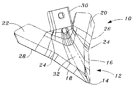
FIG. 1 is a perspective view of a sweep.
FIG. 2 is a top view of the sweep of FIG. 1.
FIG. 3 is a view taken substantially along lines 3 - - 3 of FIG. 2.
FIG. 4 is a section view of the outer wing portion taken along lines 4 - - 4
of
FIG. 2. ,
FIG. 5 is a section view of the upper portion of the sweep stem taken along
lines 5 - - 5 of FIG. 3.
FIG. 6 is a section view of the lower portion of the stem taken along lines
6- - 6 of FIG. 3.
FIG. 7 is a section view taken along lines 7 - - 7 of FIG. 3.
FIG. 8 is a view of the stem portion taken generally along lines 8 - - 8 of
FIG.
3.
FIG. 9 is another perspective view of the sweep.
F1G. 10 is another top view of the sweep.
FIG. 11 is a front view of the sweep.
FIG. 12 is a rear view of the sweep.
FIG. 13 is a bottom view of the sweep.
FIG. 14 is a right side view of the sweep.
FIG. 15 is a left side of the sweep.
Detailed Description
Referring now to the drawings, which are drawn generally to scale, therein is
shown a field cultivator sweep 10 adapted for connection to a shank attached
to an
implement frame (not shown) in a conventional manner for forward movement
through the soil. The sweep 10 includes an elongated leading nose portion 12
having a forward point 14 and straight leading cutting edges 16 and 18
diverging at
an angle less than 50 degrees. Rear wings 20 and 22 diverge from the rear of
the
3

CA 02437941 2003-08-20
nose portion 12 at locations 24 and include straight cutting edges 26 and 28
which
diverge at an angle with respect to each other of less than 75 degrees (67
degrees
as shown). At the aft end of the nose portion 12 and centrally located between
the
wings 20 and 22, an apertured connecting or stem portion 30 projects upwardly
and
rearwardfy for receipt by the shank. The stem portion 30 may be attached to
the
shank in any conventional manner, including the insertion of bolts through the
apertures in the stem and shank or the wedging of the stem on a knock-on
adaptor.
As shown in the figures, the length of the sweep 10 is greater than the width
and is longer than many conventional sweeps, in part because of the extended
nose
portion 12 with a relatively small sweep angle. Sweep angle or the angle
formed by
the intersection of the leading cutting edges 16 and 18 (FIG. 2) is
approximately 45
degrees. As shown, the edges 16, 18 and 26, 28 lie generally along a common
plane (P of FIG. 3). The nose portion 12 includes an uppermost surface or apex
32
which is generally straight and forms an angle of less than 15 degrees
(approximately 11 degrees as shown) with the plane P. The stem portion 30
extends
upwardly and rearwardly from the nose portion 12 at an angle of approximately
46
degrees.
The juncture of the edges 16, 26 and 18, 28 at locations 24 define obtuse
angles which are greater than 160 degrees and, in the example shown, are
approximately 169 degrees. The locations 24 are slightly forward of the
leading
portion of the stem portion 30 and are approximately central with respect to
the
overall length of the sweep 10. The length of the edges 16 and 18 are at least
20%
greater than the lengths of the edges 26 and 28. The wings include side edges
40
and 42 extending in the fore-and-aft direction from the edges 26 and 28 for
width
retention with wear. In the embodiment shown, the length of the sweep 10 is
approximately 10% greater than the overall width of the sweep.
The edges 16, 26 and 18, 28 are beveled and provide a self-sharpening
effect with wear. The top surfaces of the sweep nose portion extending
outwardly
4

CA 02437941 2003-08-20
from the apex 32 to the beveled edges are generally planar as are the tops of
the
wings 20 and 22. Areas subject to the highest wear may be plated or otherwise
hardened or coated to extend wear life.
Having described the preferred embodiment, it will become apparent that
various modifications can be made without departing from the scope of the
invention
as defined in the accompanying claims.

Representative Drawing
A single figure which represents the drawing illustrating the invention.
Administrative Status

2024-08-01:As part of the Next Generation Patents (NGP) transition, the Canadian Patents Database (CPD) now contains a more detailed Event History, which replicates the Event Log of our new back-office solution.

Please note that "Inactive:" events refers to events no longer in use in our new back-office solution.

For a clearer understanding of the status of the application/patent presented on this page, the site Disclaimer , as well as the definitions for Patent , Event History , Maintenance Fee  and Payment History  should be consulted.

Event History

Description Date
Inactive: Expired (new Act pat) 2023-08-21
Inactive: COVID 19 - Deadline extended 2020-08-06
Common Representative Appointed 2019-10-30
Grant by Issuance 2007-02-13
Inactive: Cover page published 2007-02-12
Pre-grant 2006-12-01
Inactive: Final fee received 2006-12-01
Notice of Allowance is Issued 2006-08-18
Letter Sent 2006-08-18
Notice of Allowance is Issued 2006-08-18
Inactive: Approved for allowance (AFA) 2006-08-09
Amendment Received - Voluntary Amendment 2006-06-05
Inactive: IPC from MCD 2006-03-12
Inactive: S.29 Rules - Examiner requisition 2005-12-08
Application Published (Open to Public Inspection) 2004-03-13
Inactive: Cover page published 2004-03-12
Inactive: First IPC assigned 2003-10-07
Inactive: IPC assigned 2003-10-07
Inactive: Filing certificate - RFE (English) 2003-09-17
Filing Requirements Determined Compliant 2003-09-17
Letter Sent 2003-09-17
Application Received - Regular National 2003-09-17
Request for Examination Requirements Determined Compliant 2003-08-20
All Requirements for Examination Determined Compliant 2003-08-20

Abandonment History

There is no abandonment history.

Maintenance Fee

The last payment was received on 2006-08-03

Note : If the full payment has not been received on or before the date indicated, a further fee may be required which may be one of the following

  • the reinstatement fee;
  • the late payment fee; or
  • additional fee to reverse deemed expiry.

Please refer to the CIPO Patent Fees web page to see all current fee amounts.

Owners on Record

Note: Records showing the ownership history in alphabetical order.

Current Owners on Record
DEERE & COMPANY
Past Owners on Record
BENOIT JOCELYN POUTRE
Past Owners that do not appear in the "Owners on Record" listing will appear in other documentation within the application.
Documents

To view selected files, please enter reCAPTCHA code :


To view images, click a link in the Document Description column. To download the documents, select one or more checkboxes in the first column and then click the "Download Selected in PDF format (Zip Archive)" or the "Download Selected as Single PDF" button.

List of published and non-published patent-specific documents on the CPD .

If you have any difficulty accessing content, you can call the Client Service Centre at 1-866-997-1936 or send them an e-mail at CIPO Client Service Centre.


Document
Description 
Date
(yyyy-mm-dd) 
Number of pages   Size of Image (KB) 
Abstract 2003-08-20 1 19
Claims 2003-08-20 3 98
Description 2003-08-20 5 183
Drawings 2003-08-20 2 77
Representative drawing 2003-10-09 1 11
Cover Page 2004-02-16 1 40
Cover Page 2007-01-22 1 41
Acknowledgement of Request for Examination 2003-09-17 1 173
Courtesy - Certificate of registration (related document(s)) 2003-09-17 1 106
Filing Certificate (English) 2003-09-17 1 160
Reminder of maintenance fee due 2005-04-21 1 110
Commissioner's Notice - Application Found Allowable 2006-08-18 1 162
Correspondence 2006-12-01 1 30