Note: Descriptions are shown in the official language in which they were submitted.
CA 02438271 2006-05-19
.. .
LIQUID DIS7'Risur[oN APPARATus FoR
DISTRIBUTING LIQUID INTO A SEED FURROW
RaLD OF THE INVENTION
Ihe invention relates to agricultural seed planters and drills, and more
particularly to seed planters and drills that include apparatus adapt:ed to
properly place
seeds in a seed fiurow and further include liquid distribution apparatvs for
distributing
liquids within the seed furrow.
15
BACI{GROi1ND OF'CHE INYENTYON
Agricultural seed planting is typically accomplished by multi-row planters and
drills. Each planter and drill comprise a plurality of row units adapted for
opening a
seed furrow, depositing seeds within the fiurow, and closing the seed fiurow
around
the seeds.
The placement of the seeds in the fiurow greatly effects the growth
characteristics of the plants. The seeds are deposited in the seed furrow
tbrougt- a
seed tube attached to the row unit. The seed tube is designed to deposit the
seeds in
1
CA 02438271 2003-08-26
Express Mail No. EV156915926US
Attomey Docket No. 5608.06
the bottom of the furrow. However, as the seeds descend through the seed tube,
they
are prone to bouncing, which ultimately affects where the seeds lie in the
furrow. In
addition, the seeds may bounce off the soil when they land in the furrow,
which also
affects where the seeds lie in the furrow. To properly place the seeds in the
bottom of
the furrow an extension may be fixed to the seed tube to properly direct the
seeds into
the vertex of the furrow.
In addition to properly placing the seeds in the vertex of the furrow, it is
oftentimes also desirable to provide various liquids in the fuzrow along with
the seeds
to facilitate plant growth and the ultimate crop yield. The liquids irncluded
in the
furrow may be liquid fertilizers, liquid insecticides, liquid starters,
inoculants, and
water. However, problems can arise when providing liquid directly into the
furrow
along with the seeds. Drenching the seed in fertilizer may result in biu7Ling
the seed
which has a negative impact on plant growth and the ultimate crop yield.
Accordingly, it is desirable to place liquids in the furrow along with the
seeds without
drenching seeds. In some instances, it is desirable to place liquid in the
furrow well
above the seeds to further avoid the risk that the liquid will come in contact
with the
seeds. Distributing a liquid higher on the seed V walls also allows a higher
concentration of fertilizer, insecticide, or other liquid to be distributed in
the furrow
without negatively impacting seed growth.
Numerous benefits are derived from in-furrow liquid distribution, such as
maxi~ the effectiveness of the liquid introduced into the fiurow, in some
situations reducing the volume of a particular liquid required to achieve a
desired
effect in other situations increasing the volume or concentration of a liquid
to achieve
a desired effect, and mininnizing the time required for a particular liquid to
effect the
seed.
Liquid fertilizer placement disks may be added to the planter row units for
placing liquid in a separate trench next to the seed fiirrow. The liquid
fertilizer
placement disks create a trench about 2 inches to the side of the seed fmTOw
and about
two inches deep and deposit liquid into the trench, which is commonly referred
to as
2x2 fertilizer application. The liquid fextilizer disks, however, are very
expensive,
2
CA 02438271 2003-08-26
Express Mail No. EV156915926US
Attorney Docket No. 5608.06
require large amounts of fertilizer because of the remote location from the
seeds, and
do not provide for in-fiurow distribution of liquid.
Referring to Figs. A-B, a KEETON SIDE SHOOTERTM in-furrow liquid
dispensing device is illustrated, the side shooter connected with a KEETON
SEED
FIRMER"~4. The seed firmer is adapted to press seeds into the seed furrow as
shown
in. Fig. A. The side shooter includes a diverter, which is shown in Fig. D and
shown
in section in Fig. F, plugged into a hose running along the length of the seed
firmer.
The diverter defines a first liquid diversion channel and a second liquid
diversion
channel for diverting liquid adjacent the seeds embedded in the farrow by the
seed
firmer as shown in Fig. B. Referring to Figs F-G, a liquid dispensing device
as
illustrated in U.S. Pat. No. 6,082,274 is shown connected with a Keeton Seed
Firmer.
There are several potential disadvantages and problems with the liquid
dispensing devices illustrated in Figs A-G. One potential problem is that
these liquid
dispensing devices have small diameter openings for the liquids to pass
through. For
example, the liquid diversion channels of the side shooter diverter are about
1/16"
diameter outlets, Heavier fertilizers in some instances do not flow evenly
from these
small diameter outlets. Additionally, when used with heavy materials such as
fertilizer that require a larger opening to pass through, these devices may
plug-up and
stop the flow of material. When plugging occurs, inadequate amounts of product
will
be placed in the furrow by the plugged lines.
Another prablem is that to avoid plugging, the liquid must be diluted with
water. For heavy liquid fertilizers, it has been found that the side shooter
in some
instances functions most efficiently if the liquid fertilizer is diluted so
that the
fertilizer flows evenly and without plugging. Diluting the fertilizer,
however, causes
problems for the application because to obtain the appropriate mnount of
liquid in the
furrow a greater volume of liquid (fertilizer diluted with water) has to be
delivered
into the furrow through the smaAer holes in the delivery system. The greater
volume
of liquid in the furrow additionally produces wemess in the funow that can
cause the
press wheels to build up with mud, which, in tum, leads to closing problems
with the
press wheels.
3
CA 02438271 2003-08-26
Express Mail No. EV 15 f 915926US
Attorney Docket No. 5608.06
Another important consideration is location-just where in the furrow the
liquid is placed. The devices illustrated in Figs. A-G in some instances
distribute
liquid on the seeds, or oftentimes within %4" on each side of the seeds in the
furrow.
Accordingly, the seeds are many times drenched in liquid, or the liquid is
within from
about 1/8" to about'/." of the seed. Besides the unwanted effects caused by
drenching
the seeds in some liquids, putting any fertilizer in such close proximity to
the seed,
especially in drier soil, draws the moisture out of the soil around it,
pulling it in close
to the seed. The concentration of liquid adjacent the seed may cause it to
germinate
more quickly than it would have under normal conditions, and early growth may
be
accelerated. If dry soil conditions persist, then the seed may run out of
moisture for
the tap root and nodule roots to pick up, which may stunt the growth of the
emerging
crop and in some instances result in the death of the crop.
It is to overcome the problems that arise when seeds are directly immersed in
various liquids and the cost and effectiveness of other devices that may be
used to
introduce liquids into a furrow that the present invention and its various
enibodiments
were developed.
There are some instances, however, when it is preferable to distribute liquids
such as fertilizer directly on the seeds in the furrow, as may be achieved
with a single
outlet hose device. Accordingly, it was recognized that it would be desirable
to
provide a single device that may distribute liquid in the furrow without
drenching the
seeds, and have the same device be convertible to also distribute fertllizer
directly on
the seeds, as needs dictate, This convertible embodiment of the present
invention
would have the benefit of allowing farmers to quickly reconfigure the device
from, for
example, a seed drenching configuration to an in-furrow liquid distribution
that does
not drench the seeds.
It was further recognized that it would be beneficial to be able to
reconfigure
the device from a single outlet configuration to a two outlet configuration,
or vice
versa, at the liquid supply tank or at the extension. If reconfigured at the
extension,
such reconfiguration should be consistently achieved. Furthermore, when the
liquid
distribution device is being used, the risk that it is inadvertently dislodged
by debris in
4
CA 02438271 2003-08-26
Express Mail No. EV 156915926US
Attorney Docket No. 5608_06
the furrow, the jostling of the tractor, and the like, or misoriented during
installation
or reconfiguration should be lessened to the extent possible so that liquids
are not
deposited in unintended portions of the fiirrow. It was also recognized that
it would
be desirable to be able to distribute one type of liquid directly on the seed
while
distributing a second liquid adjacent the seeds.
SUMMARY OF THE INVENTION
One aspect of the present invention involves an extension and liquid
distribution apparatus that may be used with a planter, dzill or other farm
implement.
Particularly, the extension may be used with a fiznrow opener for properly
placing
seeds in a furrow. The furrow opener includes a liquid supply hose for use in
distributing liquid into the seed fixrrow. The seed furrow typically has a
centrally
located bottom portion and a first sidewall and a second sidewall, the
sidewalls
extending upwardly and outwardly from the centrally located bottom portion of
the
furrow. The extension compri.ses an elongate flexible body member defining a
generally arcuate shape which provides a generally downwardly and rearwardly
sweeping orientation, and also defining an upper segment and a lower segment.
The
upper segment maybe attached to the fuxxow opener.
The lower segment is configured to depend downwardly and rearwardly from
the furrow opener and extend into the seed furrow. The lower segment
terminates at a
trailing end, and the trailing end is canfigured to be spaced above the
centrally located
bottom portion of the seed furrow. The lower segment comprises an upper
surface
defining a length, a first side and a second side. The lower segment further
comprises
a fust depression along the length of the upper surface and a second
depression
between the first depression and the first side of the upper surface.
The extension may define a third depression between the first depression and
the second side of the upper surface. The first depression, the second
depression, and
the third depression may receive a liquid distribution apparatus. The liquid
distribute
apparatus comprises a supply ch,aunel fluidly connected with the liquid supply
hose, a
distribution channel in fluid connection with the supply cliaru-el, the
distribution
5
CA 02438271 2003-08-26
Express Mail No. EV1569I5926US
Attorney Docket No. 5608.06
channel including at least one outlet angularly oriented with respect to the
supply
channel. When the supply channel is fluidly connected with the liquid supply
hose,
the at least one outlet is oriented to distribute liquid on at least one of
the sidewalls of
the furrow.
Another aspect of the present invention also involves an extension for use
with
a furrow opener for properly placing seeds in a furrow, The extension
comprises an
elongate flexible body member which provides a generally downwardly and
rearwardly orientation, and also defining an upper and lower segment. The
upper
segment may be attached to the furrow opener. The lower segment is configured
to
depend downwardly and rearwardly from the furrow opener and extend into the
seed
furrow. A first liquid distribution apparatus is connected with the lower
segment. In
addition, a second liquid distribution apparatus is connected with the lower
segment.
The first liquid distribution appaxatus comprises a supply channel adapted to
fluidly connect with the at least one liquid supply hose; and a distribution
channel in
fluid connection with the supply channel, the distribution channel including
at least
one outlet angularly oriented with respect to the supply channel. The supply
channel
is fluidly connected with the liquid supply hose, and the at least one outlet
is oriented
to distn-bute liquid on at least one of the sidewalls of the fur,row.
The furrow opener may also include a second liquid supply hose, and the
second liquid distribution apparatus may comprise an inlet and an outlet, the
inlet
adapted to fluidly connect with the second liquid supply hose. When the inlet
is
fluidly connected with the at least one supply hose, the outlet is oriented to
distribute
liquid in the centrally located bottom portion of the farrow. The first liquid
supply
hose may be connected with the second liquid distribution apparatus, and the
second
liquid supply hose may be connected with the fizst liquid distribution
apparatus.
The upper segment of the extension may define a first depression wherein the
first liquid distribution apparatus is seated within the fust depression. The
depression
may extend along the length of the extension, and may further extend between
the
length and either edge or both edges of the extension. The second liquid
distribution
apparatus may also be seated within the depression.
6
CA 02438271 2003-08-26
Express Mail No. EV 156915926US
Attorney Docket No. 5608.06
Embodiments of the present invention may be used to distribute liquid well
above the seeds in the vertex of the fiurow and may be used to distribute
liquid
directly on the seeds in the vertex of the furrow depending on the liquid
being applied.
Embodiments of the presentinvention may also be readily converted from a
configuration that deposits liquids directly on the seeds in the vertex of the
fiurow to a
configuration that deposits liquid well above the seeds along the sidewalls of
the
furrow, or vice versa. Embodiments of the present invention may also be
configured
to distribute more than type of liquid into the furrow. Embodiments of the
present
invention may also direct seeds into the vertex of the furrow.
The foregoing and other features, utilities and advantages of the invention
will
be apparent from the following more particular description of various
embodiments of
the present invention as illustrated in the accompanying drawings.
BRIEF DESCRIPTION OF THE DRAWINGS
Figure A is side view of a Keeton Seed Firrner'rm having a Keeton Side
ShooterTM connected therewith;
Figure B is a section view talcen along line B-B of Fig. A;
Figure C is a perspective view of the Keeton Seed Firmerr''" having the Keeton
Side Shooter'14 connected therewith;
Figure D is a perspective view of a diverter for use with a Keeton Side
Shooterr";
Figure E is a section view taken along line E-E of Fig. B;
Figure F is a side view of a liquid dispenser for a seed planter as shown in
U.S. Pat. No. 6,082,274, the liquid dispenser connected with a Keeton Seed
FinnerTM;
Figure G is a front view of the liquid dispenser illustrated in Fig. F;
Figure 1 is a side view of a tractor pulling an agricultural planter and
associated liquid container;
Figure 2 is a perspective view of a planter encompassing one embodiment of
the liquid distribution apparatus of the present invention, and illustrates a
tractor
pulling an agzicultural planter including a plurality of row units;
7
CA 02438271 2003-08-26
Express Mail No. EV 156915926US
Attorney Docket No. 560$.06
Figure 3 is section taken along line 3-3 of Figure 2, and illustrates a row
unit
having a hopper, a metering unit, a gage wheel, a closing wheel, a double disk
blade
furrow opener, and a seed tube depending from the metering unit with one
embodiment of an extension for reducing seed bounce, with one embodiment of
the
liquid distribution apparatus depending from the attachment;
Figure 4 is a section taken along line 4-4 of Figure 3, and illustrates the
liquid
distribution apparatuss connected to a liquid supply hose and attached to the
extension;
Figure 5 is a section taken along line 5-5 of Figure 4, and illustrates the
liquid
distribution apparatus dispersing liquid unto the sidewalls of a seed furrow;
Figure 6 is a top view of one embodiment of the liquid distribution apparatus
of the present invention;
Figure 7 is a perspective view of a seed tube, one embodiment of an extension
for reducing seed bounce, and a liquid supply hose, with one embodiment of the
liquid distribution apparatus of the present invention connected to the liquid
supply
hose and fixed to the extension;
Figure 8 is an exploded view showing a seed tube, one embodiment of the
extension for reducingseed bounce, a liquid supply hose and the liquid
distribution
apparatus of the present invention, with a mounting apparatus for mounting the
extension to the seed tube;
Figure 9 is a perspective view of a Case/IH model planter with one
embodiment of the liquid distribution apparatus;
Figure 10 is an exploded view of the CaselIEI model planter shown in
Figure 9;
Figure 11 is a perspective view of a seed tube, an embodiment of an extension
for reducing seed bounce, a liquid supply hose, and an embodiment of the
liquid
distribution apparatus wherein the liquid distribution apparatus is connected
with the
underside of the extension for reducing seed bounce;
Figure 12 is an exploded view of the seed tube, the embodiment of the
extension for reducing seed bounce, the liquid supply hose, and the embodiment
of
the liquid distribution appara.tus as shown in Fig. 11;
CA 02438271 2003-08-26
Express Mail No, EV156915926US
Attorney Docket No. 5608.06
Figure 13 is a section taken along line 13-13 of Fig. 11;
Figure 14 is a section taken along line 14-14 of Fig. 13;
Figure 15 is a bottom view of the embodiment of an extension for reducing
seed bounce, and the embodiment of the liquid distribution apparatus. wherein
the
liquid distribution apparatus is connected with the underside of the
extension;
Figure 16 is a section taken along line 16-16 of Fig. 15;
Figure 17 is a perspective view of a seed tube, one embodiment of an
extension for reducing seed bounce, and a liquid supply hose, with one
embodiment
of the liquid distribution apparatus having three outlets connected to the
liquid supply
hose and fixed to the extension4
Figure 18 is a section view taken along line 18-18 of Fig. 17;
Figure 19 is a section view taken along line 19-19 of Fig. 18;
Figure 20 is a perspective view of one embodiment of a diverter for use, in
one
example, in conjunction with the two outlet embodiment of the liquid
distribution
apparatus;
Figure 2:1 is a front view of the diverter illustrated in Fig. 20;
Figure 22 is top view of the diverter illustrated in Fig. 20;
Figure 23 is a side view of the diverter illustrated in Fig. 20;
Figure 24 is perspective view of an alternative embodiment of a diverter for
use, in one example, in conjunction with the two outlet embodiment of the
liquid
distribution apparatus;
Figure 25 is a&-ant view of the diverter illustrated in Fig. 24;
Figure 26 is a side view of the diverter illustrated in Fig. 24;
Figure 27 is a side view of a seed tube, one embodiment of an extension for
reducing seed bounce, and a liquid supply hose, with a single outlet liquid
distribution
apparatus connected to the liquid supply hose and fixed to the extension, the
outlet
being forward of the trailing end of the extension so that the liquid
disperses over the
top of the extension and into the fiurow;
9
CA 02438271 2003-08-26
Express Mail No, EV 156915926US
Attonaey Docket No. 5608.06
Figure 28 is a section view,taken along line 28-28 of Fig. 27, illustrating
the
dispersion of the liquid across the vertex of the furrow and extend'zng
partially up the
sidewalls of the ~uurow;
Figure 29 is a section view taken along line 29-29 of Fig. 27, illustrating
the
dispersion of liqu'td across the vertex of the fusrow and extending partially
up the
sidewall of the furrow;
Figure 30 is a perspective view of a seed firmer having a two outlet
embodiment of the present invention connected therewith;
Figure 31 is a section view taken along line 31-31 of Fig. 30;
Figure 32 illustrates a seed firmer having a three outlet embodiment of the
present invention connected therewith
Figure 33a is a section view taken along line 33-33 of Fig. 32 illustrating
the
three outlet embodiment of the present invention with all of the outlets
unplugged;
Figure 33b is a section view taken along line 33-33 of Fig. 32 illustrating
the
three outlet embodiment of the present invention with the center outlet
plugged, the
three outlet embodiment configured to distribute liquid on the sidewalls of
the furrow;
Figure 33c is a section view taken along line 33-33 of Fig. 32 illustrating
the
tbree outlet embodiment of the present invention with the side outlets
plugged, the
three outlet embo;diment configured to disttibute liquid in the vertex of the
furrow;
Figure 34 is a perspective view of one embodiment of a plug for use in
plugging the outlets to reconfigure the three outlet embodiment;
Figure 35a illustrates an exploded perspective view of a BuffaloTM planter
with one embodiment of an extension for reducing seed bounce attached thereto,
the
extension having an embodiment of the liquid distribution apparatus coupled
therewith;
Figure 35b illustrates an exploded perspective view of a Landoll Quadra.T"t
planter with one embodiment of an extension for reducing seed bounce attached
thereto, the exten5ion having an embodiment of the liquid distribution
apparatus of
the present invention coupled therewith;
CA 02438271 2003-08-26
Express Mail No. EV 156915926US
Attomey Docket No. 5608.06
Figure 35c illustrates a side view of a John Deere 71 F1exTM planter with one
embodiment of an extension for reducing seed bounce attached thereto, the
extension
having an embodiment of theliquid distribution apparatus of the present
invention
coupled therewith;
Figure 35d illustrates a side view of an Allis ChahnersT14 model 78 or 79
planter with one embodiment of an extension for reducing seed bounce attached
thereto, the extension having, an embodiment of the liquid distribution
apparatus of
the present invention coupled therewith;
Figure 35e illustrates a perspective view of Allis ChambersTx model 500 or
600 planter with one embodiment of an extension for reducing seed bounce
attached
thereto, the extension having an embodiment of the liquid distribution
apparatus of
the present invention coupled therewith;
Figure 35f illustrates an exploded perspective view of a Case IIirM model 400
or 500 planter having a boot with one embodiment of an extension for reducing
seed
bounce attached thereto, the extension having an embodiment of the liquid
distribution apparatus of the present invention coupled therewith;
Figure 35g illusttates an exploded view of a Case IRTM model 400 or 500
planter having an Acra-Plant boot with one embodiment of an extension for
reducing
seed bounce attached thereto, the extension having an embodiment of the liquid
distribution apparatus of the present invention coupled therewith;
Figure 35h iIlustrates an exploded vievv of a Case IFPM 400 or 500 planter
having an Acra Plant runner with one embodiment of an extension for reducing
seed
bounce attached thereto, the extension having an embodiment of the liquid
distribution apparatus of the present invention coupled therewith;
Figure 35i illustrates and exploded view of a Case IIPM model 56 planter with
one embodiment of an extension for reducing seed bounce attached thereto, the
extension having an embodiment of the liquid distribution apparatus of the
present
invention coupled therewith;
il
CA 02438271 2003-08-26
Express Mail No. EV156915926US
Attomey Docket No. 5608.06
Figure 35j illustrates an exploded view of a Case IHTm 1200 ASM planter with
an embodiment of the liquid distribution apparatus of the present invention
attached
thereto;
Figure 36a illustrates a side view of a John DeereTM mode1750 single disc
drill with one embodiment of an extension for reducing seed bounce attached
thereto,
the extension having an embodiment of the liquid distribution apparatus of the
present
invention coupled therewith;
Figure 36b illustrates a side view of a John DeereTM model 1560 or 1860
single disc drill with one embodimern of an extension for reducing seed bounce
attached thereto, the extension having an embodiment of the liquid
distribution
apparatus of the present invention coupled therewith;
Figure 36c illustrates a side view of a Flexi-Coil FSP'"s single disc
drillwith
one embodiment of an extension for reducing seed bounce attached thereto, the
extension having an embodiment of the liquid distribution apparatus of the
present
invention coupled therewith;
Figure 37a illustrates a side view of a FSOTM single disc opener with one
embodiment of an extension for reducing seed bounce attached thereto, the
extension
having an embodiment of the liquid distribution apparatus of the present
invention
coupled therewith;
Figure 37b illustrates a side view of a banding and spreading boot with an
embodiment of the liquid distnbution apparatus of the present invention
attached
theretwith;
Figure 37c illustrates a side view of a paired row boot having a shoe with one
embodiment of an extension fq'r reducing seed bounce attached thereto, the
extension
having an embodiment of the liquid distribution apparatus of the present
invention
coupled therewith;
Figure 37d illustrates a side view of an eagle beak having a boot with one
embodiument of an extension f Ir reducing seed bounce attached thereto, the
extension
having an em.bodiment of the l i iquid distribution apparatus of the present
invention
coupled therewith;
12
CA 02438271 2003-08-26
Express Mail No. EV156915926US
Attorney Docket No. 5608.06
Figure 38a illustrates a side view of a KrauseTM model 5400 double disc drill
with one embodiment of an extension for reducing seed bounce attached thereto,
the
extension having an embodiment of the liquid distribution apparatus of the
present
invention coupled therewith;
S Figure 38b illustrates a side view of a KrauseTM model 5200, 5250 or 5500
double disc drill with one embodiment of an extension for reducing seed bounce
attached thereto, the extension having an embodiment of the liquid
distribution
apparatus of the present inveation coupled therewith;
Figure 38c illustrates a side view of a SunflowerTM double disc drill with one
embodiment of an extension for reducing seed bounce attached thereto, the
extension
having an embodiment of the liquid distribution apparatus of the present
invention
coupled therewith;
Figure 38d illustrates a side view of a TyeT"I double disc drill with one
embodiment of an extension for reducing seed bounce attached therewith, the
extension having an embodiment of the liquid distribution apparatus of the
present
invention coupled therewith;
Figure 38e illustrates a side view of a TyeTM soybean/rice double disc drill
with one embodiment of an extensioa for teducing seed bounce attached
therewith,
the extension having an embodiment of the liquid distribution apparatus of the
present
invention coupled therewith;
Figure 38f illustrates a side view of a"CIF"ITm double disc drill with one
embodiment of an extension for reducing seed bounce attached therewith, the
extension having an embodiment of the liquid distribution apparatus of the
present
invention coupled therewith;
Figure 38g itlustrates a side view of a John DeereT',imode1750 double disc
drill with one embodiment of an extension for reducing seed bounce attached
therewith, the extension having an embodiment of the liquid distribution
apparatus of
the present invention coupled therewith;
Figure 38h illustrates a side view of a John Deere'tM mode1455, 515 or 8300
double disc drill having gaugewheels mounted along side the double disc
openers
13
CA 02438271 2003-08-26
Express Mail No. EV 156915926UUS
Attorney Docket No. 5608.06
with an embodiment of the liquid disttibution apparatus of the present
invention
attached therewith;
Figure 38i illustrates a John DeereTM mode1455, 515 or 8300 double disc drill
having single or double press wheels with an embodiment of the liquid
distribution
apparatus of the present invention attached therewith;
Figure 38j illustrates a John DeereTM model 8300 double disc drill having a
press wheel not attached to the drill, with an embodiment of the liquid
distribution
apparatus of the present invention attached therewitb;
Figure 38k illustrates a MarlissTm double disc drill with an embodiment of the
liquid distribution apparatus of the present invention attached therewit'h;
Figure 381 illustrates a BestTM double disc drill with an embodiment of the
liquid distribution apparatus of the present invention attached therewith;
Figure 38m illustrates a Great PlainsTM double disc drill with an embodiment
of the liquid distribution apparatus of the present invention attached
therewith;
Fignre 38n illustrates a Crustbuster'rM mode13400 or 3700 double disc drill
with an embodiment of the liquid distribution apparatus of the present
invention
attached therewith;
Figure 38o illustrates a CrustbusterTm model 4000 double disc drill with an
embodiment of the liquid disiiibutioa apparafius of the present invention
attached
therewith;
Figure 38p illustrates a HaybusterT"s double disc drill with an embodiment of
the liquid distribution apparatus of the present invention attached therewith;
Figure 38q illustrates a Case IHTM mode15100, 5300 or 5400 double disc drill
with an embodiment ofthe liquid distribution apparatus of the present
invention
attached therewith;
Figure 39 is an isometric view of one embodiment of an extension defining a
depression for locating a liquid distribution apparatus;
Figure 40 is an isometric view of the extension illustrated in Fig. 39 with a
two
outlet liquid distribution apparatus coupled thereto;
Figure 41 is a side view of the exte'nsion shown in Fig. 40;
14
CA 02438271 2003-08-26
Express Mail No. EV156915926US
Attorney Docket No. 5608.06
Figure 42 is a top view of the extension taken along line 42-42 of Fig. 41;
Figure 43 is a side view of the extension illustrated in Fig. 39 with a single
outlet liquid distribution appara.tus coupled thereto;
Figure 44 is a top view of the extension taken along line 4 4 - 4 4 of Fig.
43;
Figure 45 is an isometric view of the extension shown in Fig. 39 with a two
outlet liquid distribution apparatus and a single outlet l,iquid distribution
apparatus
coupled therewith;
Figure 46 is a side view of the extension illustrated in Fig. 45; and
Figure 47 is a top view of the extension taken along line 47-47 of Fig. 46.
DETAILED DESCRIPTION OF THE PREFERRED EMBODIMENT
While various embodiments of the liquid distribution apparatus can be used
with a variety of planters, drills and liquid supply devices, it will be
initially described
as used with a double disk furrow opener style agricultural planter 102 pulled
behind
a tractor 104. Furthermore, the liquid distribution apparatus will be
described in a
configuration wherein a large liquid container 106 is pulled behind the
planter 102
providing a liquid supply to the liquid distribution apparatus through a
liquid supply
hose 196. The liquid container 106, however, is oftentimes integrated with the
planter
102 or the tractor 104. Nonetheless, the liquid distribution apparatus
functions
equally well regardless of the location of the liquid container 106,
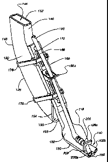
The agricultural planter 102, shown in Figs. 1-3, typically includes a number
of planter row units 108 mounted on a main frame member 110. The planter 102
is
pulled in a forward direction F by the tractor 104. Each row unit 108 forms a
seed
furrow 110, deposits seeds 112 evenly along the seed furrow 310, supplies a
liquid
114 in the fuirow 110, and then closes the seed furrow 110 to form a seed bed
116.
The liquid distribution apparatus 100 of the present invention is embodied in
a two-
outlet Y-shaped configuration 100, shown in Figs. 4-10, that distributes the
liquid 114
into the furrow I 10 along with the seeds 112 without drenching the seeds 112.
In this
embodiment, the liquid distribution apparatus 100 is used along with an
extension
118, shown in Figs. 4-10, which reduces seed bounce as the seeds 112 exit each
row
CA 02438271 2003-08-26
Express Mail No. EV 156915926US
Attomey Docket No. 5608.06
unit 108, and helps position the seeds 112 optimally in the vertex or bottom
portion
120 of the furrow 110 prior to closure of the fiurow 110 by the row unit 108.
To
avoid drenching the seeds 112 in the liquid 114, the liquid distribution
apparatus 100
deposits the liquid 114 on the sidewalls 122 of the furrow 110. Preferably,
the liquid
S is deposited at least %"above the bottom portion 120 of the furrow 110. More
preferably, the liquid is deposited between about %," and'/. " above the
bottom
ponion 120 of the fvzrow 110.
Each row unit 108, as seen in Figs. 1-3, comprises a seed hopper 124 for
holding and dispensing seeds 112, a seed metering unit 126 positioned below
the seed
hopper 124 that receives the seeds 112 from the seed hopper 124, and a seed
tube 128
positioned below the seed metering unit 126 that receives seeds 112 from the
metering unit 126 to place in the fiurow 110. A furrow opening apparatus 130
is
positioned generally beneath the seed hopper 124, and includes a residue
divider 132
at the leading edge of each row unit 108, and a furrow opener 134 positioned
more
centrally under the hopper 124, The fiut'ow opener 134 is partaally
encompassed by a
pair of gage wheels 136, and a pair of furrow closer wheels 138 which trail
behind the
furrow opener 134 and gage wheels 136.
The seed furrow 110 is formed by the furrow opener 134 attached to each row
unit 108. Although numerous types of openers are known in the art such as
double
disc, single disc, shoe, boot, and runner style openers that the present
invention may
be used with, a double disk furrow opener 134 is shown in Figs. 1-3. The
double disk
opener 134 includes two circular disk blades 139 rotatably mounted on a row
unit 108
to form a V-shape at the point of seed placement. The disk blades 139 have a
diameter, and the peripheral edges 140 of each disk blade 139 are adjacent to
one
another at the point where they form the V. The gage wheels 136 flank the disk
blades 139 to support the row unit 108 and allow the disk blades 139 to mold a
V-
shaped seed furrow 110 at a predetermined depth within the soil.
The fvrrow 110 formed by the furrow opener 134 is generally V-shaped, as
shown best in Fig. 4, with the bottom portion 120 forming the vertex where the
upwardly and outwardly extending sidcwalls 122 interseeL Under ideal soil
16
CA 02438271 2003-08-26
Express Mail No. EV 156R915926US
A.ttorney Docket No. 5608.06
conditions, the fiurow 110 maintains the V-shape until closed by the furrow
closer
wheels 138. In moist conditions, the soil along the sidewalls 122 is pulled
loose,
causing portions of the soil to lodge in the bottom portion 120 of the furrow
110 and
along the sidewalls 120. Also, as the disk blades 139 wear out, they become
smaller
in diameter and the adjacent edges 140 of the disk blades 139 become spaced
apart.
As the disk blades 139 wear down, the increased spacing between the adjacent
edges
140 causes the furrow to gradually transform into a W-shape.
The seed tube 128 extends downwardly from the metering unit 126, between
the disk blades 139 (or into the boot or shoe), and is positioned directly
over the seed
furrow 110 adjacent to the rear 142 of the double disk blades 139, as shown in
Fig. 3.
The metering unit 126 regulates the distribution of seeds 112 from the seed
hopper 124 to the seed tube 128. Tb.us, the seeds 112 are optimally evenly
spaced
along the seed furrow 110 as they fall from the seed tube 128.
As shown in Figs. 3, 5, 7 and 8 the seed tube 128 is attached to and extends
downwardly from the meter unit 126. The seed tube 128 has an elongated hollow
main body 144, with a generally rectangular cross-sectional structure defining
a
rearwardly facing surface 146, a forwardly facing surface 148, and opposing
side
facing surfaces 150. The seed tube 128 has a slight arcuate shape along its
length in
the reazward direction. An upper end 152 of the seed tube 128 is attached to
the meter
unit 126, while a downwardly depending lower and trailing end 154 of the seed
tube
128 depends downwardly between the disk blades 139 so as to be positioned over
the
bottom portion 120 of the furrow 110. The downwardly depending end 154 defines
an opening 156 thtough which the seeds 112 exit the seed tube 128 and fall
into the
furrow 110. The lower end 154 of the seed tube 128 is swept rearwardly from
the
upper end 152 as a result of the slight arcuate shape. The forwardly facing
surface
148 of the seed tube 128 is longer than the rearwardly facing 146 surface of
the seed
tube 128, such that the forwardly facing surface 148 forms a lower edge 158 of
the
opening 156, while the rearwardly facing surface 146 of the seed tube 128
defines the
upper edge 160 of the opening 156.
17
CA 02438271 2003-08-26
Express Mail No. EV 15fi915926US
Attorney Docket No. 5608.06
A pair of protrusions 162 extend from the rearwardly facing surface 146 of the
seed tube 128. The protrusions 162 are spaced longitudinally with respect to
one
another along the length of the seed tube 128: Each protrusion 162 can have an
aperture 164 formed laterally therethrough.
The seed tube 128 guides the seeds to the furrow 110, as seen in Figs. 3-6. As
the seeds 112 flow through the seed tube 128, they bounce around as a result
of
in.teraction with the walls 122 of the seed tube 128 as well as the movement
of the
planter 102 over the ground. The rearward curve of the seed tube 128, as well
as the
orientation of the exit opening 156, are designed to compensate for the
forward
motion of the planter 102, and ideally the seeds 112 drop into the furtow 110
very
gently, However, since the seeds 112 bounce as they niove through the seed
tube 128,
they oftentimes drop out of the seed tube 128 at a less than optimal angle, or
the seeds
112 bounce outwardly from the opening 156 of the seed tube 128 prior to
hitting the
ground, causing the seeds 112 to then bounce upwardly when they hit the
ground.
The bouncing of the seeds 112 results in the seeds being disbursed throughout
the furrow 110, not only along the bottom portion 120, but along the sidewalls
122
and often outside the seed furrow. The bouncing seeds 112 result in the seeds
being
improperly positioned within the ffiurow 110. The improper placement of the
seeds
within the furrow 110 results in various growth related problems such as
uneven pant
emergence, poor stands, increased weed population, non unifoxm maturing,
longer
inseet life cycles, higher susceptibility to chemical damage, and ultimately
lower
yields. Moving the planter 102 at a slower velocity reduces the bouncing
problem,
but does not eliminate it. Moving the planter 102 at a liigher velocity to
increase the
planting process exacerbates the bouncing problem.
As seen in Figs. 3-8, the exteasion 118 is preferably mounted on the
rearwardly facing surface 146 of the seed tube 128 near its depending lower
end 154.
Alternatively, or as seen in Figs. 9 and 10, the extension 118 may be mounted
on
other row unit shuctures such as a seed boot or shoe. The extension 118
facilitates
the proper placement of seeds 112 in the bottom portion 120 of the furrow 110
thereby significantly reducing the problems associated with improper seed
placement
18
CA 02438271 2003-08-26
Attorney Docket No. 5608.06
as discussed above. The extension 118 extends downwardly and rearwardly from
the
seed tube 128 into the furrow 110, minimizing contact with the sidewalls 122.
Preferably, the extension 118 terminates at a position just above the vertex
120 of the
furrow.
With the extension 118 mounted on the depending lower end 154 of the seed
tube 128, as the seeds 112 exit the opening 156 of the seed tube 128 and
bounce from
the seed tube, the seeds 112 contact the extension 118 and deflect back into
the furrow
110. If the seeds 112 bounce more than once within the furrow 110, they will
again
contact the extension 118 further along its length and will again be deflected
back into
the fiurow 110. As the seeds 112 come to rest in the bottom portion 120 of the
furrow
110, the trailing end 186 of the extension 118 passes over the seeds 112
without
contacting the seeds 112. The extension effectively ftuznels the seeds to the
bottom of
the furrow. In the preferred embodiment when attached with the seed tube, the
width
of the extension decreases rearwardly along its length so that the width of
the
extension closely matches the width of the furrow as the extension extends
rearwardly
and downwardly into the furrow, thereby reducing the nurnber of seeds that can
bounce between the sidewall of the furrow and the eactension.
In mounting the extension 118 to the seed tube 128, as best seen in Figs. 4,
5,
7 and 8, the top segment 166 of the extension 98 is releasably attached to the
seed
tube 128. More particularly, ine one embodiment of the extension, the
prohusions
162 on the seed insert tube 128 are positioned within the apertures 168 formed
in an
attachment 170 having outwardly facing sidewalls defining a sawtooth pattern
172
complimentary to a sawtooth configiuation 174 defxned by an elongated slot 176
in
the extension 118. The complimentary sawtooth configura.tions 172 and 174
provide
an adjustment mechanism to place the extension at the appropriate depth into
the
furrow 110. The engagement of the prrotrusions 162 in the mounting apertures
168
properly position the extension 118 on the seed tube 128, and acts to inhibit
any
longitudinal or transverse movement of the extension 118 with respect to the
seed
tube 128. Two releasable fasteners 178, such as plastic tie straps, are
positioned
around the extension 118 and the seed tube 128, and are releasably fastened
thereto to
19
CA 02438271 2003-08-26
Express Mail No. BV 156915926US
Attorney Docket No. 5608.06
hold the extension 118 securely in position on the seed tube 128. The
extension can
also be fastened to the seed tube or planter in any known manner.
In one embodiment, the bottom segment 180 of the extension I 18 defines an
upwardly convex top surface 182 and a downwardly concave lower surface 184.
The
downwardly concave lower surface 184 acts to deflect the bouncing seeds 112
toward
the center 120 of the furrow 110. The seeds 112 are thus directed toward and
land in
the bottom portion 120 of the furrow 110. This helps place the seeds 112 in
the
optimal position within the furrow 1;10, and helps reduce the number of seeds
which
come to rest on the sidew+ralls 122 or outside of the furrow 110. In short,
the
downwardly concave lower surface 184 of the bottom segment 180 of the
extension
118 focuses the deflection of the seeds 112 toward the bottom portion 120 of
the
furrow 110, as shown in Figs. 4-6. -
The transverse dimension of the lower surface 184 of the bottom segment 180
of the extension 118 preferably becomes substantially planar adjacent to the
trailing
end 186 because the transverse dimension of the extension 118 is substantially
reduced, and a downwardly facing concave surface has less of an effect on the
deflection of the seeds given the proximity of the trailin,g end 186 to the
bottom
portion 120 of the flirrow110. Also, very few seeds continue to bounce at that
location on the extension.
The extension 118 is flexible along its entire length so that in the event the
trailing end 186 of the extension comes into contact with the soil, the
trailing end of
the extension will easily bend upwardly to minimize any damage to a seed 112
that
may be contacted. Furthermore, while the extension 118 is designed to not
contact
the sidewalls 122 of the furrow 120 during use, some incidental contact may
occur.
Any incidental contact with furrow may have the affect of covering the seeds
112 in
the bottom portion 120 of the fiurow 110 with a thin layer of soiL This helps
to
protect the seeds from any incidental contact with the liquid 114 that may
occur. The
extension can also have any number of shapes and cross-secttons, and can
contact the
furrow bottom or sidewalls.
CA 02438271 2003-08-26
Express Mail No. EV156915926US
Attorney Docket No. 5608.06
Including liquids 114 such as liquid fertilizer, liquid starter, liquid
insecticides,
liquid inoculants, and water in the f+urow 110 along with the seeds 112 at the
time of
planting advantageously affects the growth of the plants and the ultimate
yield of the
crop as discussed above. The provision of some types of liquid 114 directly
into the
furrow 110, however, can actually negatively affect plant growth and the
ultimate
crop yield if liquid 114 is distributed directly unto the seeds 112.
Accordingly, one
embodiment of the liquid distribution apparatus 100 of the present invention
directs
liquid 114 unto the sidewalls 120 of the fmow, above the seeds 112, thus
providing
liquid 114 directly into the furrow 120 along with the seeds 112 without
drenching the
seeds 112 in the liquid 114. Although the liquid distribution apparatus 100 of
the
present invention is shown in the Figures in conjunction with one embodiment
of the
extension 118, a Schaffert Manufacturing Co., Inc., RebounderTm, the liquid
distribution apparatus may also be used in the absence of the extension 118.
In the
absence of the extension 118, however, a larger proportion of seeds 112 may
become
deposited on the furrow sidewalls 122 and hence come in direct contact with
the
distributed liquid 114 from the present invention. The majority of seeds 112,
however, will still be deposited in or near the bottom portion 120 of the
furrow 110,
therefore the present invention is advantageous to plant growth and crop yield
even in
the absence of the extension 118. The present invention may also be used in
conjunction with other available seed placement attachnnents such as a Keeton
Seed
Firrner'='M.
Liquid 114 is supplied to the liquid distribution apparatus 100 of the present
invention from the liquid container 106. The liquid container includes a pump
188 in
fluid connection with the contents of the liquid container 106 for supplying
liquid
under pressure. As shown in Figure 1, a main hose 190 connects to the pump 188
to
the liquid distribution tube 192 at the upper rear of the planter 102. The
liquid
distribution tube 192 on the planter 102 traverses the width of the planter
102 aomss
the planter row units 108. Adjacent each row unit 108, the liquid distribution
tube
192 has an outlet 194 that is fluidly coupled to a liquid supply hose 196.
Each row
21
CA 02438271 2003-08-26
Express Mail No_ EV 156.915926US
Attorney Docket No. 5608.06
unit 108 has the liquid supply hose 196 for distributing liquid to the fuxrow
110
associated with each row unit 108.
The liquid supply hose 196 extends generally downwardly from the
distribution tube 192 to the seed tube 128 and is attached to the extension
118. The
extension 118 attached to the seed tube 128 preferably includes at least two
eyelets
198a and 198b along its length. The first eyelet 198a is located along the top
segment
166 of the extension 118. The liquid supply hose 196 extends through the first
eyelet
198a and is thereby held in place along the center of the extension 118.
Preferably,
the first eyelet 198a fits loosely around the hose 196 so that as the
extension lexes the
hose may move freely with the eyelet 198a, which helps to prevent the hose 196
from
disconnecting the hose 196 from the liquid distribution apparatus, A second
eyelet
198b is located along the top of the extension 118 adjacent the bottom segment
180 of
the extension 118 that extends into the furrow I 10. Preferably, the second
eyelet
198b grips the supply hose 196 firmly to help prevent the hose 196 from
disconnecting from the liquid distribution apparatus 100. An additional third
eyelet
198c may be included along the length of the extension between the first
eyelet 198a
and the second eyelet 198b. The third eyelet 198c helps to hold the hose 196
secure
so that residue flowing over the top of the extension does not disconnect the
hose 196
from the liquid distribution apparatus.
The liquid distribution apparatus 100 is preferably attached to the bottom
segment 180 of the extension 118 adjacent the furrow 110. The liquid
distribution
apparatus 100 is preferably secured to the extension 118 with the second
eyelet 198b
and is in fluid connectio.n with the liquid supply hose 196. In the two-eyelet
embodiment of the liquid distribution apparatus 100, shown in Figs. 4,5,7 and
8, the
liquid distribution apparatus 100 generally defines a Y-shaped tubular
structure .
having a supply tube 200 in fluid connection with the liquid distribution hose
196 and
two distribution tubes 202a and 202b in fluid connection with the supply tube
200, the
distribution tubes distributing liquid 114 on the sidewalls 122 of the furrow
110
generally above the two vertexes of the furrow.
22
CA 02438271 2003-08-26
Express Mail No. EV156915926US
Attorney Docket No. 5608.06
Generally speaking, the liquid distribution apparatus 100 includes a supply
channel 200 and a distribution channel 202 having at least two outlets 202a
and 202b.
However, it is to be understood that the distribution channel 202 may comprise
any
structure that distributes liquid unto one or both sidewalls 122 of the furrow
110. The
supply channel 200, as shown in Figures 4-10, comprises a tubular structure or
hose
that is in fluid connection with the liquid supply hose 196 at its rear end.
Preferably,
the inlet portion of the supply channe1200 includes a barbed or ribbed portion
204 to
engage the liquid supply hose 196. The outlet portion of the supply channel
200 is in
fluid connection with the distribution channel 202.
The distribution channe1202 as shown in the embodiment of the liquid
distribution apparatus show in Figs. 4-10, includes two outlets 202a, 202b,
angularly
oriented with respect to the supply channel 200, that distribute liquid along
one or
both sidewalls 122 of the furrow 120. The outlets 202a, 202b, in this
embodiment,
comprise tubular structures or hoses. The front portion of the distribution
channel 202
is attached to the center of the extension 118 by the second eyelet 198b. The
liquid
distribution apparatus 100 may be held in place in the second eyelet 198b by
an
adhesive or a tie strap, Accordingly, the outlets 202a, 202b, are oriented
along the
bottom segment 180 of the extension with the first outlet 202a extending
outwardly to
one side of the extension 118 and the second outlet 202b extending outwardly
to the
opposite side of the extension 118. As shown in the Figures, the outlets 202a,
202b,
along with the supply tube 200 form a generally Y-shaped structure.
As shown in Figures 5 and 6, when liquid 114 flows from the outlets 202a,
202b, the liquid 114 is preferably distributed above the bottom portion 120 of
the
furrow 110 along the sidewalls 122 of the furrow. By distributing the liquid
114
along the sidewalls 122 of the fuurrow 110, the seeds 112 are not drenched in
the liquid
114 because most of the seeds 112 are deflected by the extension 118 to the
bottom
portion 120 of the furrow 110 below where the liquid is distributed.
As shown in Figures 4-10, the liquid distribution apparatus 100 is attached
along the bottom segment 180 of the extension 118 bye the second eyelet 198b.
The
liquid supply hose 196, that is attached to the extension 118 at the first
eyelet 198a, is
23
CA 02438271 2003-08-26
Express Mail No. EV 156915926US
AttACney Docket No. 5608.06
in fluid connection with the liquid distribution apparatus 100 adjacent the
second
eyelet 198b. As mentioned above, the use of the extension 118 is considered
preferable, but is not necessary to the proper functioning of the liquid
distribution
apparatus 100. For example, the liquid distribution apparatus 100 can be
attached
along the center top portion of the seed tube 128 directly above the opening
156
where the seeds 112 exit the seed tube 128. Attached to the seed tube 128, the
outlets
202a, 202b, will extend outwardly and to either side of the seed tube 128
thereby
depositing liquid 114 along the sidewalls 122 of the furrow I 10.
Generally, the liquid distribution apparatus 100 may be attached to any part
of
the planter row unit 108. Preferably, the liquid distribution apparatus 100
(when not
attached to the extension 118) is attached at a location between the double
disk opener
134 and the furrow closer wheel 138 centered along the vertex 120 of the
furrow so as
to orient the outlets. 202a, 202b above the sidewalls 122 of the seed furrow
110 before
the fitzrow 110 is closed.
The embodiments of the liquid distribution apparatus 100 are shown and
described as being attached to the bottom segment 180 of the extension 118.
The
various embodiments of the liquid distribution apparatus may, however, be
attached
anywhere along the extension so long as, in the case of the two-outlet
embodiment,
the outlets 202a, 202b axe oriented so as to distribute liquid 114 along the
sidewalls
122 of the furrow. The location of the liquid distribution apparatus 100 on
the
extension as shown in the Figures is considered preferable..
Additionally, while the various embodiments of the liquid distribution
apparatus are shown as a separate structure attached to the extension 118,
they may,
however, be integrated into the extension 118. To integrate the liquid
distribution
appara.tus 100 into the extension the supply channel 200 and distribution
channel 202
can be molded directly into the extension in a single plastic injection mold.
In the
integrated liquid distribution apparatus, the supply channe1200 is in fluid
connection
with the liquid supply hose 196 and a plurality of outlets from the
distribution channel
202 are oriented so as to distribute liquid into the furrow .110.
24
CA 02438271 2003-08-26
Express Mail No. BV1S6915926US
Attoraey Docket No. 5608.06
Figures 9 and 10 show the two outlet embodiment of the liquid distribution
apparatus 100 of the present invention connected to an extension that is
attached to a
CaseM style planter having a seed boot 204 positioned between the disks (not
shown). The extension 118 is attached directly to the seed boot 204. A brace
plate
206 may be necessary to properly attach the extension 118 to the seed boot
204. The
seed tube 128 (not shown) typically extends through the seed boot.
Tfae liquid supply hose 196 is connected to the outside of the seed boot 204
using a tie strap 208. The lower end of the liquid supply hose 196 is in fluid
connection with the liquid distribution apparatus 100 connected to the
extension 118.
Accordingly, the outlets 202a and 202b of the two outlet embodiment of the
liquid
distribution apparatus 100 distribute liquid 114 unto the sidewalls 122 of the
furrow
110,
In an alteruative embodiment illustrated in Fig. 11, the liquid distribution
apparatus 100 is connected to an extension 210 adjacent the downwardly concave
lower surface 184 of the extension 210. Preferably, in this embodiment the
outlets
202a, 202b of the Iiquid distribution apparatus 100 are located between the
underside
184 of the extension 210 and the seed chute 128. The liquid supply hose 196
extends
generally downwardly from the distribution tube 192 to the seed tube 128, and
extends through a fust eyelet 198a which projects upwardly from the extension
210.
Rearwardly of the eyelet 198a, the liquid supply hose 196 extends from the top
surface 212 of the extension 210 through the elongated slot 176 to the
underside 214
of the exteasion 210, where it is fluidly connected with the supply channel
200 of the
apparatus 100. The extension 210 preferably includes an eyelet 198d projecting
downwardly, and generally transversely, from the extension 210. The eyelet
198d
couples the apparatus 100 to the extension 210, and properly orients the
outlets 202a,
202b of the apparatus 100 to distribute liquid on the sidewalls 122 of furrow
110. The
liquid distribution apparatus 100 extends through the eyelet 198d, and is
fluidly
connected with the liquid supply hose 196 ad.j aeent thereto. In the case of
the
distribution apparatus 100 having three outlets, the center outlet is oriented
to
distribute liquid in the vertex 120 of the furrow 110.
CA 02438271 2003-08-26
Express Mail No. EV156915926US
Attorney Docket No, 5608.06
Fig. 12 is an exploded view showing the top section 166 of the extension 210
connected with the seed tube 128. This connection is shown and described in
detail
above with respect to Fig. 8, the only difference in Fig. 12 is the presence
of an
alternative embodiment of the extension 210 which has an eyelet 198d extending
downwardly, and generally transversely, from extension 210. This eyelet 198d
properly orients the outlets 202a, 202b of the liquid distribution apparatus
200 below
the extension 210.
Fig. 13 is a section taken along 13-13 of Fig. 11. This view shows the
orientation of the distribution apparatus 100 extending through the eyelet
198d for
distribution of liquid beneath the extension 210 on the sidewalls 122 of the
fuirow
110. Fig. 13 also shows the liquid supply hose 196 passing through the
elongated slot
176 from the top surface 212 of the extension 210 to the underside surface
214. Figs.
14-16 are views which show the alternative embodiment of the extension 210 and
the
orientation of the liquid supply tube and the liquid distribution apparatus
100 coupled
therewith.
This altemative embodiment provides for the additional advantage of
preventing the outlets 202a, 202b of the liquid distribution apparatus 100
from
becoming clogged with soil during use. The location of the liquid distribution
apparatus 100 underneath the extension 210 shields the outlets 202a, 202b from
any
soil that may inadvertently fall on the extensioa from the filling of the
furrow 110 by
the fiurow closer wheels (not shown) occuriing behind the extension 210 after
depositing the seeds and the liquid into the fiurow 110.
Referring to Figs. 17-19, an alternative embodiment of the liquid distribution
apparatus 100 includes three outlets 202a, 202b, 202c in a preferably fork
shaped
configuration (qi) with respect to the supply channel 200, wherein one of the
outlets
202c is oriented to distribute liquid 114 in the centrally located bottom
portion 120 of
the fiurow, and the other two outlets 202a, 202b are oriented to distribute
liquid 114
on opposing sidewalls 122 of thefurrow 110, Generally, this embodiment
provides a
farmer or other user with a convertible liquid distribution apparatus 100 that
may
distribute liquid on the sidewalls 122 of the furrow I 10, in the vertex 120
of the
26
CA 02438271 2003-08-26
Express Mail No. EV156915926US
Attorney Docket No. 5608.06
furrow 110, or in any combination thereof. This allows the fanner to rapidly
convert
the liquid distribution portion of the planter for planting seeds that benefit
from liquid
distributed on the furrow sidewalls to planting seeds that benefit from liquid
distribution directly on the seeds.
Preferably, the liquid distribution apparatus 100 includes a supply channel
200
similar to other embodiments described herein and a distribution channel 202.
The
distribution channel 202 preferably having three outlets 202a, 202b, 202c,
wherein a
ftrst 202a and a second side outlet 202b are preferably angularly oriented
with respect
to the supply channel 200, which may distribute liquid along one or both
sidewalls
122 of the furrow 110, and a third or center outlet 202c that is preferably co-
linear
with the supply channel 200, which may distribute liquid 114 centrally located
in the
bottom or vertex 120 of the furrow 112. This embodiment is described as
preferably
having three outlets; it is envisioned, however, that this embodiment could
include
more than three outlets.
As with preceding exemplary embodiments of the liquid distribution apparatus
100, the izilet portion of the supply channel includes a barbed or ribbed
portion 204 at
its rear end to engage the liquid supply hose 196. The outlet portion of the
supply
channel 200 is in fluid connection with the distribution channel 202.
Accordingly,
fluid flows from the first hose 196 into the supply channel 200 and then out
to the
outlet(s) 202a, 202b, 202c of the distribution channel 202.
This alternative convertible embodiment preferably also includes at least one
stopper or plug 216 adapted to stop or reduce the flow of liquid 114 from any
of the
outlets 202a, 202b, 202c, thereby allowing the device to be converted to
different
liquid distnbution patterns. I'n one embodiment, the stopper or plug 216 may
be
connected with the liquid distribution apparatus 100, with the extension 118
or 210
for reducing seed bounce, or with whatever device the apparatus 100 is
connected
with, for example a drill, by way of a cable or other such connection device
so that
when not in use the plug 216 stays connected with the liquid distribution
apparatus
100. Preferably, the plug 216 is held to the apparatus by way of some
retentive means
27
CA 02438271 2003-08-26
Express Mail No. EV 1 S6915926US
Attorney Docket No. 5608.06
such as a snap, clamp, or the like (not shown). Alternatively, the plug 216
may be
supplied in a kit along with the liquid distribution apparatus 100.
The plug 216 is adapted to be inserted into the outlets 202a, 202b, 202c
thereby prohibiting the flow of liquid 114 from the plugged outlet. This
allows the
apparatus 100 to be converted to any liquid distribution configuration the
farmer
desires. For example, for certain applications, such as placing liquid
ferti.tixers in the
furrow 110, it is desirable to distribute liquid 114 on the sidewalls 122 of
the furrow
110 and not directly on the seeds 112; accordingly, the farmer will insert a
plug 216
into the center outlet 202c. In another example, if the farmer is distributing
liquid
inoculant in the furrow 110 along with the seeds 112, it is desirable to place
the
inoculant directly on the seed 112; accordingly, the farmer will insert a plug
216 in
the .first 202a and second 202b side outlets.
In an alternative einbocliment, the plug 216 is preferably permanently coupled
within the distrtbution end 202 of the outlet. In this embodiment, liquid flow
may be
adjusted by pulling the plug 216 outward to allow fall flow, or pressing the
plug
inwardly to decrease the flow. Fully depressed, the plug 216 prohibits liquid
flow
from the outlet(s) 202a, 202b, 202c altogether.
One advantage of this convertible embodiment is the ease by which a farmer
may change from an in-furrow on-seed liquid dist ir bution set-up (where the
first 202a
and second 202b outlets are plugged) to an in-futrow sidewall distribution set-
up
(where the center outlet 202c is plugged) or vice versa For example, a farmer
may
desire to plant corn seeds and distribute inoculauts (which faailitate rapid
germination
and growth) directly on the seeds 112 in one portion of the farm, and then
change
seed types to soy beans and distribute fertilizer on the sid.ewalls 122 of the
furrow 110
above the soy bean seeds for planting in a different portion of the farm.
Changing
from the on-seed liquid, distribution for the corn seeds to the furrow
sidewall
distribution for the soy beans simply requires that the farmer prohibit the
liquid flow
from the center outlet 202c, and allow the liquid flow from the side outlets
202a,
202b. In one embodiment, the farmer will remove the side plugs, and insert a
center
28
CA 02438271 2003-08-26
Express Mail No. EV156915926US
Attorney Docket No. 5608.06
plug; or, in are alternative embodiment, the farmer will depress the center
plug, and
pull-out the side plugs.
Referring to Fig. 20, a perspective view of one embodiment of a diverter 218
is shown for use, in one example, in conjunction with the two outlet 202a,
202b
embodiment of the liquid distribution apparatus 100. Fig. 21 is a front view
of the
diverter 218 illustrated in Fig. 20; Fig. 22 is top view of the diverter 218
illustrated in
Fig. 20; and Fig. 23 is a side view of the diverter 218 illustrated in Fig.
20. The
diverter may be used to configure the two-outlet 202a, 202b embodiment of the
liquid
distribution apparatus 100 for either on-seed liquid distribution, or liquid
distribution
on the sidewalls 122 of the furrow 110 above the seeds 112. The diverter 218
includes an integrated upper outlet 220 and an integrated lower outlet 222 in
fluid
connection with an integrated supply channe1224 whuch is adapted to be fluidly
coupled with the liquid supply hose (not shown). The rearward portion of the
diverter
is insertable into the eyelet 198c and thereby is connected with the extension
118. As
shown and described above, the liquid distribution apparatus 100 extends
through the
rearward most eyelet 198b of the extension. Rather than connecting directly
with the
liquid supply hose as shown above, the liquid distribution apparatus 200 plugs
into
one of the two outlets 220, 222 of the diverter which supplies liquid to the
liquid
distribution apparatus 100.
The farnner may then through the use of plugs 216 configure the device 218
for distribution of liquid directly into the furrow 110 (by plugging the
outlets of the
liquid distribution apparatus 100, and leaving the outlet not occupied by the
liquid
distribution appaiaius unplugged) or configure the device for distribution of
liquid on
the sidewalls 122 of the furrow 110 (by plugging the outlet not occupied by
the liquid
distribution apparatus, and leaving the outlets 202a, 202b of the liquid
distribution
apparatus unplugged).
Referring to Fig. 24 an alternative embodiment of a diverter 218 for use, in
one example, in conjunction with the two outlet embodiment of the liquid
distribution
appara.tus 100. Fig. 25 is a front view of the diverter 218 illustrated in
Fig. 24; and
Fig. 26 is a side view of the diverter 218 illustrated in Fig. 24. The
diverter 218 may
29
CA 02438271 2003-08-26
Express Mail No. EV 156915926US
Attorney Docket No. 5608.06
be used to configure the two outlet embodiment of the liquid distribution
apparatus
100 for either on-seed liquid distribution, or liquid distribution on the
sidewalls 122 of
the furrow 110 above the seeds 112, The diverter 218 includes an upper
distribution
tube 220 and a lower distribution tube 222 in fluid connection with a supply
tube 224
which is adapted to be fluidly coupled with the liquid supply hose (not
shown). The
rearward portion of the diverter is irnsertable into the eyelet 198c and
thereby is
connected with the extension 118. As shown and described above, the liquid
distribution apparatus 100 extends through the rearward most eyelet 198b of
the
extension i 18. Rather than connecting directly with the liquid supply hose as
shown
above, the liquid distribution apparatus plugs into one of the two liquid
distribution
tubes 220, 222 of the diverter 218 which supplies liquid 114 to the liquid
distribution
apparatus 100.
The fanner may then, through the use of plugs 216, configure the device for
distribution of liquid directly into the furrow 110 (by plugging the outlets
of the liquid
distribution apparatus, an.a leaving the liquid distribution tube not occupied
by the
liquid distribution apparatus unplugged) or configure the device for
distribution of
liquid on the sidewalls 122 of the .fiuxow 110 (by plugging the liquid
distribution tube
not occupied by the liquid distribution apparatus, and leaving the outlets
202a, 202b
of the liquid distribution apparatus unplugged).
Figs. 27-29 illustrate an alternative embodiment of the present invention
wherein the liquid tube 196 extends along the leagth of the extension 118,
nearly to
the trailing end 186 of the extension, but not past the end of the extension
118.
Preferably, the end of the tube is placed on the longitudinal centerline of
the extension
118. In this embodiment, tiie liquid 114 flowing from the tube 196 spreads out
over
the surface 182 of the extension 118 and flows into the fixrrow 110. The
upwardly
convex shape of the upper surface 182 of the extension 118 causes the liquid
flowing
from the tube 196to spread out fairly evenly in about a 180-degree radius from
the
end of the tube 196, depending on the pres$ure that the fluid is flowing out
of the
tube. Under fairly low-pressure conditions, if the tube is placed very near
the trailing
end 186 of the extension 118, then fluid will flow unto both sidewalls 112 of
the
CA 02438271 2003-08-26
Express Mail No. EV1S6915926US
Attorney Docket No. 5608.06
furrow 110 and into the vertex 120 of the furrow 110. In contrast, if the end
of the
tube is placed toward the middle or widest point of the extension 118, then
the vast
majority of the fluid 114 flowing from the tube is deposited on the sidewalls
122 of
the furrow I10.
The width of the extension 118 narrows along its length from about its
midpoint to the trailing end 186. Accordingly, at the widest point of the
extension the
fluid is distributed well above the vertex 120 of the furrow 110. Whereas, at
the
trailing end 186 of the extension 1 l8 the fluid 114 is deposited primarily in
the vertex
120 of the furrow 118. The amount of fluid deposited on the sidewalls 122, as
compared to the amount deposited zn the vertex 120 of the furrow 110, will
change
depending on the location of the end of the tube 196along the length of the
extension
118 and the pressure at which the fluid 114is flowing out of the tube 196.
Figs. 30-31 illustrate a seed firming device such as the Keeton Seed
FirmerT'*'
with the two outlet embodiment of the liquid distribution apparatus 100
connected
therewith. Figs. 32-33c iltustrate the seed fimiing device with the three
outlet
embodiment of the liquid distribution apparatus 100 connected therewith.
During
planting, the seed fiimer generally drags behind the planter, drill or other
irnplement
in the furrow 110 contacting the bottom portion 120 of the furrow 110. In
contacting
the bottom portion of the furrow, the seed firmer contacts the seeds 112 that
are in the
bottom of the portion of the fiarrow and embeds the seeds in the dirt. The
firmer
includes an arm adapted to contact the seeds in the funrow during plantitig
which is
atxached to the planter. The arm is adapted to contact the seeds in the
furrow. It is
envisioned that the various embodizneats of the liquid distribution apparatus
may be
used with the seed firmer to distribute liquid in the furrow while the seed
firmer is
embedding the seeds in the fnmw.
Fig. 34 illustrates is a perspective view of one embodiment of a plug used in
connection with any of the above-described embodiments of a liquid
distribution
apparatus to reduce or eliminate the flow of liquid therefrom.
Referring now to Figs. 35a-35j various embodiment of the present invention
are illustrated. Fig. 35a illustrates an exploded perspective view of a
Suffalo"'
31
CA 02438271 2003-08-26
Express Mail No. EV156915926US
Attorney Docket No. 5608.06
planter with one embodiment of an extension for reducing seed bounce attached
thereto. The extension, as shown, may have the two outlet or three outlet
embodiment
of the liquid distribution apparatus connected therewith. The liquid
distribution
apparatus being in fluid connection with the liquid supply hose. Fig. 35b
illustrates an
exploded perspective view of a Landoll QuadraT" planter with one enzbodimemt
of an
extension for reducing seed bounce atta.ched thereto. The extension, as shown,
niay
have the two outlet or three outlet embodiment of the liquid distribution
apparatus
c,onnected therewith. The liquid distribution apparatus being in fluid
conn,ection with
the liquid supply hose. Fig. 35c illustrates a side view of a John Deere 71
FlexT'i
planter with one embodiment o~an extension for reducing seed bounce attached
thereto. The extension, as shown in Fig 35c, may have the two outlet or three
outlet
embodiment of the liquid distribution apparatus connected therewith. The
liquid
distribution apparatus being in fluid connection with the liquid supply hose.
Fig. 35d
illustrates a side view of an AIIis ChalmersTM model 78 or 79 planter with one
embodiment of an extension for reducing seed bounce attached thereto. The
extension, as shown in Fig. 35d, may have the two outlet or three outlet
embodiment
of the liquid distribution appatatus connected therewith. The liquid
distribution
apparatus being in fluid connection with the liquid supply hose. Fig. 35e
illustrates a
perspective view of AAis ChambersTM model 500 or 600 plaater with one
embodiment of an extension for reducing seed bounce attached thereto. The
extension, as shown in Fig. 35e, may have the two outlet or three outlet
embodiment
of the liquid distribution apparatus connected therewith. The liquid
distribution
apparatus being in fluid connection with the liquid supply hose, Fig. 3Sf
ilIustrates an
exploded perspective view of a Case IIfrm model 400 or 500 planter having a
boot
with one embodiment of an extension for reducing seed bounce attached thereto.
The
extension, as shown in Fig. 35~ may have the two outlet or three outlet
embodiment
of the liquid distribution apparatus connected therewith. The liquid
distribution
apparatus being in fluid connection with the liquid supply hose. Fig. 35g
illustrates an
exploded view of a Case lIiw model 400 or 500 planter having an Acra-Plant
boot
with one embodiment of an extension for reducing seed bounce attached thereto.
The
32
CA 02438271 2003-08-26
Express Mail No. EV156915926US
Attorney Docket No. 5608.06
extension, as shown in Fig. 35f, may have the two outlet or three outlet
embodiment
of the liquid distribution apparatus connected therewith. The liquid
distribution
apparatus being in fluid connection with the liquid supply hose. Fig. 35h
illustrates an
exploded view of a Case IEiT"' 400 or 500 planter having an Acra-Plant runner
with
one embodiment of an extension for reducing seed baunce attached thereto. The
extension, as shown in Fig. 35h, may have the two outlet or three outlet
embodiment
of the liquid distribution apparatus connected therewith. The liquid
distribution
apparatus being in fluid connection with the liquid supply hose. Fig. 35i
illustrates
and exploded view of a Case THTM model 56 planter with one embodiment of an
exteasion for reducing seed bounce attached thereto. The extension, as shown
in Fig.
35i, may have the two outlet or three outlet embodiment of the liquid
distribution
apparatus connected therewith. The liquid distribution apparatus being in
fluid
connection with the liquid supply hose. Fig. 35j illustrates an exploded view
of a
Case IIRTM 1200 ASM planter with an embodiment of the liquid distribution
apparatus
of the present invention attached thereto. The extension, as shown in Fig.
35j, may
have the two outlet or three outlet embodiment of the liquid distribution
apparatus
connected therewith. The liquid distribution apparatvs being in fluid
connection with
the liquid supply hose. Additionally, a diverter may be used along with any of
the
embodiments shown in Figs. 35a-35j.
Referring now to Figs. 36a-36c various embodi.ment of the present invention
are illustrated with single disc drills. Fig. 36a illustrat.es a side view of
a Jolm
DeereTU model 750 single disc drill with one embodiment of an extension for
reducing seed bounce attached thereto. The extension, as shown in Fig. 36a,
may
havc the two outlet or three outlet embodiment of the liquid distribution
apparatus
connected therewith. The liquid distributioa apparatus being in fluid
connection with
the liquid supply hose. Fig. 36b illustrates a side view of a John DeereTM
model 1560
or 1860 single disc drill with one embodunent of an extension for reducing
seed
bounce a#tached thereto. The extension, as shown in Fig. 36b, may have the two
outlet or three outlet embodiment of the liquid distribution apparatus
connected
ther+ewith. The liquid distribution apparatus being in fluid connectiozi with
the liquid
33
CA 02438271 2003-08-26
Express Mail No. EV156915926US
Attorney Docket No. 5608.06
supply hose. Fig. 36c illustrates a side view of a Flexi-Coil FS1TM single
disc drill
with one embodiment of an extension for reducing seed bounce attached thereto.
The
extension, as shown in Fig. 36c, may have the two outlet or three outlet
embodiment
of the liquid distribution apparatus connected therewith. The liquid
distribution
apparatus being in fluid connection with the liquid supply hose. Additionally,
a
diverter may be used along with any of the embodiments shown in Figs. 36a-36c.
Refercing now to Figs. 37a-37d various embodiment of the present invention
are illustrated with various single disc openers. Fig. 37a illustrates a side
view of a
FSOTM single disc opener with one embodiment of an extension for reducing seed
bounce attached thereto. The extension, as shown in Fig. 37a, may have the two
outlet or three outlet embodiment of the liquid distribution apparatus
connected
therewith. The liquid distribution apparatus being in fluid connection with
the liquid
supply hose. Fig. 37b illustrates a side view of a banding and spreading boot
with an
embodiment of the liquid distribution apparatus of the present invention
attached
theretwith. The extension, as shown in Fig. 37b,may have the two outlet or
three
outlet embodiment of the liquid distribution apparatus connected therewith.
The
liquid distribution apparatus being in fluid connectioa with the liquid supply
hose.
Fig. 37c illustrates a side view of a paired row boot having a shoe with one
embodiment of an extension for reducing seed bounce attached thereto. The
extension, as shown in Fig. 37c, may have the two outlet or three outlet
embodimeut
of the .liquid distribution apparatus connected therewith. The liquid
distribution
apparatus being in fluid connection with the liquid supply hose. Fig. 37d
illustrates a
side view of an eagle beak having a boot with one embodiment of an extension
for
reducing seed bounce attached thereto. The extension, as showa in Fig. 37d,
may
have the two outlet or three outlet embodiment of the liquid distribution
appara.tus
connected therewiith, The liquid distribution apparatus being in fluid
connection with
the liquid supply hose. Additionally, a diverter tnay b e used along with any
of the
embodiments shown in Figs. 37a-37d.
Referring now to Figs. 38a-38q various embodiments of the present invention
are illustrated with various double disc drills. Fig. 38a illustrates a side
view of a
34
CA 02438271 2003-08-26
Express Mail No. EV 156915926US
Attoiney Docket No. 5608.06
KrauseTm model 5400 double disc drill with one embodiment of an extension for
reducing seed bounce attached thereto. The extension, as shown in Fig. 38a,
may
have the two outlet or three outlet embodiment of the liquid distribution
apparatus
connected therewith. The liquid distribution apparatus being in fluid
connection with
the liquid supply hose. Fig. 38b illustrates a side view of a Krauser"
mode15200,
5250 or 5500 double disc drill with one embodiment of an extension for
reducing seed
bounce attached thereto. The extension, as shown in Fig. 38b, may have the two
outlet or three outlet embodiment of the liquid distribution apparatus
connected
therewith. The liquid distribution apparatus being in fluid connection with
the liquid
supply hose. Fig. 38c illustrates a side view of a SunflowerT"s double disc
drill with
one einbodiment of an extension for reducing seed bounce attached thereto, The
exteasion, as shown in Fig. 38c, may have fhe two outlet or three outlet
embodiment
of the liquid distribution appas=atus connected therewith. The liquid
distribution
apparatus being in fluid conneetion with the liquid supply hose. Fig, 38d
illustrates a
side view of a TyeTM double disc drill with one embodiment of an extension for
reducing seed bounce attached therewith. The extension, as shown in Fig, 38d,
may
have the two outlet or three outlet embodiment of the liquid distribution
apparatus
connected therewith. The liquid distribution apparatus being in fluid
connection with
the liquid supply hose, Fig. 38e illustrates a side view of a TyeT-u
soybean/rice double
disc drill with one embodiment of an extension for reducing seed bounce
attached
therewith. The extension, as shown in Fig. 38e, may have the two outlet or
three
outlet embodiment of the liquid distribution apparatus connected therewith.
The
liquid distribution apparatus being in fluid connection with the liquid supply
hose.
Fig. 38f illustrates a side view of a UFTIm double disc drill with one
embodiment of an extension for reducing seed bounce attached therewith. The
extension, as shown in Fig. 38f, may have the two outlet or three outlet
embodiment
of the liquid distribution apparatus connected therewith. The liquid
distribution
apparatus being in fluid connection with the liquid supply hose. Fig. 38g
illustrates a
side view of a John DeereTM mode1750 double disc drill with one etnbodiment of
an
extension for reducing seed bounce attached therewith. The exteosion, as shown
in
CA 02438271 2003-08-26
Express Mail No. EV1S6915926US
Attorney Docket No. 5608.06
Fig. 38g, may have the two outlet or three outlet embodiment of the liquid
distribution
apparatus connected therewith. The liquid distribution apparatus being in
fluid
connection with the liquid supply hose. Fig. 38h illustrates a side view of a
John
DeereTM mode1455, 515 or 8300 double disc drill having gauge wheels mounted
along side the double disc openers with an embodiment of the liquid
distribution
apparatus of the present invention attached therewith. Fig. 38i illustrates a
John
DeereTm mode1455, 515 or 8300 double disc drill having single or double press
wheels with a two outlet or three outlet embodiment of the liquid distribution
apparatus of the present invention attached therewith, Fig, 38j illustrates a
John
DeereTH mode18300 double disc drill having a press wheel not attached to the
drill,
with a two outlet or three outlet embodiment of the liquid distribution
apparatus of the
present invention attached therewith. Fig. 38k illustrates a MarlissTM double
disc drill
with a two outlet or three outlet embodiment of the liquid distribution
apparatus of the
present invention attached therewith. Fig. 381 illustrates a BestTM double
disc drill
with a two outlet or three outlet embodiment of the liquid distribution
apparatus of the
present invention attached therewith.
Fig. 38m illustrates a Great PlainsTM double disc drill with a two outlet or
three outlet embodime.nt of the liquid distribution apparatus of the present
invention
attached therewith. Fig. 38n illustrates a CrustbusterTM model 3400 or 3700
double
disc drill with a two outlet or three outlet embodiment of the liquid
distribution
apparatus of the present invention attached therewith. Fig. 38o illustates a
CrustbusterTm mode14000 double disc drili with a two outlet or three outlet
embodiment of the liquid distribution apparatus of the present invention
attached
therewith. Fig. 38p illustrates a HaybusterTM double disc drill with a two
outlet or
tbree outlet embodiment of the liquid distribution apparatus of the present
invention
attached therewith. Fig. 38q illustrates a Case Il=P'M model 5100, 5300 or
5400 double
disc drill with a two outlet or three outlet embodiment of the liquid
distribution
appazatus of the present invention attached therewith. Additionally, a
diverter may be
used along with any of the embodiments shown in Figs. 38a-38q.
36
CA 02438271 2003-08-26
Express Mail No. EV 156915926US
Attorney Docket No. 5608.06
Including liquids 114 such as liquid fertilizer, liquid starter, liquid
insecticides,
liquid inoculants, and water in the fuzrow 120 along with the seeds 112 at the
time of
planting advantageously affects the growth of the plants and the ultimate
yield of the
crop as discussed above. The provision of some types of liquid 114 directly
into the
furrow I 10, however, can actually negatively affect plant growth and the
ultimate
crop yield if liquid 114 is distributed directly on the seeds 112. Conversely,
for some
liquids and some types of seeds, it is preferable to provide liquid 114
directly on the
seeds 112. Using the various liquid distnibution apparatuses described above,
it is
possible to dispense liquid 114 on the sidewalls 122 of the fuzrow 110 above
the seeds
112 or directly on the seeds 112.
In some instances, it is preferable to dispense liquid 114 well above the
vertex
120 of the furrow 110 and the seeds 112 therein. This allows a higher
concentration
of liquid 114, such as fertilizers, nitrogen, zinc, pot ash, sulfur,
insecticides, and the
like, to be deposited in the fiurow 110 along with the seeds 112, while
lessening the
risk that the higher concentration liquid will damage the seeds. As the
extension 118
is pulled along in the furrow I 10, it is jostled by the tractor rolling over
the uneven
surfaces typically found in fields, by dirt and mud faliing on the extension
118, and by
other events. Thus, it is important to keep the liquid distribution apparatus
100 firmly
held to the extension I I8 so that the liquid distribution apparatus 100 is
not
inadvertently reoriented by the jostling. Otherwise, such jostling might cause
liquid
114, whether high concmtration or not, to be distributed in unintended pordons
of the
furrow 110.
Fig. 39 illustrates one embodiment of an extension 226 conforming to the
present inventioa Figs. 40-47 illustrate the extension 226 with various tiquid
distribution apparatus configurations cannected therewith, each conforming to
various
aspects of the present invention. Figs, 40-42 illustrate the extension 226
with a two
outlet liquid distribution apparatus 228. The two outlet liquid distribution
device 228
is orieated on the extension 226 to distribute liquid 114 on the sidewalls 122
well
above the vertex 120 of the fusow 110 to allow higher concentration liquids
114 to be
itsed without damaging the seeds 112 located in the vertex 120. Figs_ 43-44
illustrate
37
CA 02438271 2003-08-26
Express Mail No. EV 156915926US
Attorney Docket No. 5608.06
the extension 226 with a one outlet liquid distribution apparatus 230. The one
outlet
liquid distribution device is oriented on the extension to distribute liquid
on the seeds
in the vertex 120 of the furrow 110.
Aspects of the invention allow the extension 226 to be quickly reconfigured
from a one outlet liquid distribution configuration to a two outlet liquid
distribution
configuration or vice versa. For either a single outlet configuration 230 or a
two
outlet configuration 228, the liquid distribution device is located in a
depression 232
defined along the top surface 234 of the extension 226. The depression 232
helps to.
hold the liquid disttibution apparatus (228, 230) in place. The depression 232
also
facilitates changing the configuration from a one outlet setup to a two outlet
setup.
Figs. 45-47 illustrate an extension 226 with both a one outlet 230 and a two
outlet 2281iquid distribution device. This configuration allows for
distribution of
liquid 114 on only the sidewalls 122, only the vertex 120, or both the vertex
120 and
the sidewalls 122 with the sarne or different liquids. It also allows for
reconfiguration
of the liquid distribution by changing the liquid feed line at the liquid
container 106
rather than swapping liquid distribution devices at the extension 226.
Referring now to Fig. 39, an isometric view of one implementation of an
extension 226 confozming to the present invention is shown. The top surface
234 of
the bottom segment 236 of the extension 226 defines depression 232 to accept
one or
more liquid distribution apparatuses. Generally, a liquid distribution
apparatus (228,
230) is seated in the depression 232 to locate and to help stabilize the
liquid
distribution apparatus as the extension 226 is pulled tbzough the fizrrow 110.
The extension 226 is typically mounted to the seed tube 128. As best shown
in Figs. 4, 5, 7, and 8, the top segment 166 of the extension 226 is
releasably attached
to the seed tube 128. In one example, described in detail above, the upper
segment
166 defines an elongate slot 176 having a saw tooth pattern configured to
cooperate
with an attachment fixed to the seed tube that define a complimentary saw
tooth
pattern. The cooperating saw tooth pattecns allow the user to adjust the depth
that the
extension extends down in the furrow 110.
38
CA 02438271 2003-08-26
Express Mail No. EV156915926US
Attorney Docket No. 5608.06
Refetring again to Fig. 39, in one implementation, the bottom surface 238 of
the extension 226 defines a generally concave surface 240 that acts to deflect
seeds
112 into the vertex 120 of the furrow 110 after they exit the seed tube 129
and bounce
around in the furrow 110. The extension 226 includes sidewalls 242 defining a
S gen.erally narrowing width to conform as much as possible to the V-shaped
fiurow
110 as the extension 226 extends therein. Aspects of the present invention,
however,
may be adapted for use with an extension that do not have a concave bottom
surface
and does not have a narrowing width.
The depression 232 in the top surface 234 of the bottom segment 236
comprises a reanvard section 244, a funt 246 and a second 248 angularly
orientated
section, and a forwardly extending section 250. The rearward section 244 and
the
forward section 250 are defined generally along the length of the extension
226 and in
combination define a single continuous depression 232. The combined depression
232 extends along the length of the extension 226 in front of the second
eyelet 198b.
For reference, the second eyelet 198b is located towards the rear of the
liquid
distribution apparatus (228, 230) when it is attached to a farming imptement.
The
first angularty oriented section 246 extends from the combined depression 232
to one
side 252 of the extension 226. The second angularly oriented sectiora 248
extends
from the combined depression 232 to the opposite side of the extension.
The de.gression 232 is fottned, in ane example, to receive the corresponding
tubular portions of sorne of the embodiments of the liquid distxibution
apparatus
described herein. Figs. 40-42 illustrate a side view and a top view,
respectively, of
the extension 226 with an embadiment of the two outlet liquid distribution
apparaxus
228 received in the depression 232. Particularly, the supply channel 200 of
the liquid
disttibution apparatus 228 is reaeived in the forward saetion 250 of the
depression
232, and the two outlets (202a, 202b) are each received in the respective
first 246 and
second 248 anguiarly orientated sections. No portion of the liquid
distribution
'apparatus 228 is received in the rearward section 244. In this implementation
of the
extension 226, the first and second angularly orientated sections (246, 248)
are swept
rearwardly to canform to the orientatioa of the outlets (202a, 202b).
39
CA 02438271 2003-08-26
Express Mail No. EV15f915926US
Attorney Docket No. 5608.06
To distribute liquid into the furrow 110, the supply channel portion 200 of
the
Y-sh,aped liquid distribution apparatus 228 is fluidly connected with the
liquid supply
hose 196. In one example, both the supply channel 200 and the liquid supply
hose
196 are inserted into a sleeve 256 so that liquid 114 may flow from the supply
hose
196 to the liquid distribution apparatus 228. The outlets (202a, 202b) are
arranged to
distribute liquid 114 onto opposing sidewalls 122 of the furrow 110 well above
the
vertex region 120 where the majority of the seeds 112 are located.
The depression 2321ocates the liquid distribution apparatus (228, 230)
forwardly of the second eyelet 198b. Other embodiments, such as those shown in
Figs. 5, 6, and others,'i,llustrate the supply portion of the liquid
distiibution apparatus
within the second eyelet 198b, and the outlets (202a, 202b) to the rear of the
second
eyelet 198b. In these embodiments, liquid 114 is distributed on the sidewalls
122
nearer to the vertex 120 of the furrow 110. From the seed tube 128, the
extension 118
extends rearwardly and downwardly toward the vertex 120 of the furrow 110. The
extension 118 also narnows as it extends down into the furrow 110. Referring
again to
Figs. 40-42, by locating the outlets (202a, 202b) forwardly of the second
eyelet 198b
and generally further from the rear of the liquid distribution apparatus 228,
the outlets
(202a, 202b) are higher on the extension 226. This causes the liquid 114 to be
distributed higher on the sidewalls 122 of the furrow 110 above the seeds 112
in the
vertex region 120. rn some instances, the outlets (202a, 202b) are lengthened
as
compared with other implementations so that they extend ta the sides (252,
254) of
the extension along its wider sections. By leagthening the outlets (202a,
202b), the
distance or width between the outlets increases, which also causes liquid 114
to be
distributed higher on the sidewalls 122. As mentioned above, placing the
liquid 114
higher an the sidewalls 122 and thus further from the seeds 112 in the vertex
120
allows a higher concentration of liquid 114 to be distributed in the furrow
110.
The extension 226 may include a clamp that secures the sleeve 256, the supply
hose 196, and the liquid distribution appazatus (228, 230) to the extension
226, The
sleeve 256 is placed in the clamp 258 to receive the liquid supply hose 196
and the
supply channe1200, and the clamp 258 secures them together within the sleeve
256.
CA 02438271 2003-08-26
Express Mail No. EV156915926US
Attoraey Docket No. 5608.06
By loosening the clamp 258, the various embodiments of the liquid distribution
apparatus may be swapped out quickly and efficiently. For example, if the user
desires to change from a sidewall distribution configuration to a vertex
distribution
configuration, then a two outlet configuration may be exchanged for a straight
one
outlet configuration (see Figs. 43-44 discussed below).
The clarap 258 maybe a bracket 262 fixed to the sleeve 256 by way of bolts
264, screws, or the like. To receive the bolts 264 or screws, the extension
226 may
define a raised area 260 defining one or more threaded apertures. To
facilitate
repeated loosening and tightening of the clamp 258, a threaded sleeve formed
from a
metallic or other durable material may be fixed within the apertures defined
in the
exteosion 226. In another alternative, a hinged clamp 266 may be used. The
hinged
clamp 266 is fixed to the extension 226 along one side of the sleeve 256 and
also
provided with a hinge 268. The clamp may then be arranged to pivot over the
sleeve
256, and snap into a receiver 270 located on the opposite side of the sleeve
256.
Figs. 43-44 illustrate a side view and a top view, respectively, of the
extension
226 with a single outlet liquid distribution apparatus 230 received in the
depression
232. The single outlet distribution apparatus 230, in one example, is a
straight section
of hose 272 defining an inlet 274 and an outlet 276. The inlet 274 is fluidly
connected
with the liquid supply hose 196. The inlet region 274 is inserted in the
sleeve 256,
which also receives the liquid supply hose 196. The sleeve 256, the inlet 274
of the
straight hose 272, and the liquid supply hose 196 are then secured to the
extension
226 with the clamp 258. A portion 278 of the hose 272 between the inlet 274
and the
outlet 276 is acranged within the second eyelet 198b to fwrther secure the
hose 272 to
the extension 226. The outlet 276 of the hose 272 is arranged adjacent the
very rear
of the extension 226 to deposit liquid 114 on the seeds 112 located in the
vertex 120
region of the furrow 110.
The length of hose between the sleeve 256 and the second eyelet 198b is
located in the continuous portion of the depression 232 nuuung along the
length of the
extension 226 in front of the second eyelet 198b. The depression 2321Yelps to
locate
41
CA 02438271 2003-08-26
Express Mail No. EV156915926US
Attorney Docket No. 5608.06
the hose 272 when it is being inserted in the sleeve 256, and also helps to
secure the
hose 272 to the extension 226 during use so that it is not dislodged.
For a user to switch from the two outlet liquid distribution apparatus 228 to
the
single outlet 230, or vice versa, the user first loosens the clamp 258. The
user then
removes the liquid distribution apparatus (228, 230) by pulling it free from
the sleeve
256. The new liquid distribution apparatus (228, 230) is then inserted into
the sleeve
256, located in the depression 232, and the clamp 258 tightened. Thus, removal
and
replacement of liquid distribution apparatuses (228, 230) may be petformed
quiclcly
and efficiently by the user.
The depression 232 helps to locate the liquid distribution apparatus (228,
230)
when it is being installed. To properly connect a liquid distribution
apparatus (228,
230) to an extension 226, after insertion into the sleeve 256, but before
clamping, the
user places the liquid distribution apparatus (228, 230) within the depression
232, and
then clamps it to the extension 226. Thus, the liquid distribution apparatus
(228, 230)
can be consistently located to the extension 226. This is especially useful
for the two
outlet embodiment 228. It is important for the outlets (202a, 202b) to be
properly
located to distribute liquid 114 into the furrow 110. For example, if the
outlets (202a,
202b) were arranged closer to the rear of the extension 226, then the liquid
114 would
be distributed closer to the vertex 120 of the furrow 110, which might cause
damage
to the seeds 112 if a high concentration liquid 114 is used. The depression
232
ensures that the two outlets (202a, 202b) are always located along the same
part of the
extension 226. The user can also verify that a liquid distribution apparatus
(228, 230)
has not been dislodged during use by determining whether the liquid
distribution
apparatus (228, 230) is located correctly within the depression 232.
While the extension 226 is being pulled through the furrow 110, it may run
into any number of obstauctioas, such as the sidewalls 122, mud and dirt
falling onto
the extension 226, and rocks or other debris in the furrow 110. Such
obstructions may
act to dislodge or dislocate the liquid distribution apparatus, which can
result in liquid
114 being inadvertently deposited in unintended regions of the furrow 110. For
example, if the two outlet liquid distribution apparatus 228 is dislodged so
that one of
42
CA 02438271 2003-08-26
Express Mail No. EV 156915926US
Attorney Docket No. 5608.06
the outlets 202 is near the center of the extension 226, liquid 114 might be
distributed
on the seeds 112 when it was intended to be distributed along the sidewa11122.
The depression 232 also helps to keep the liquid distribution apparatus (228,
230) consistently located along the extension 226 when various obstructions
are
encountered during planting. Portions of the liquid distribution apparatus
(228, 230)
are encompassed within the depression 232, which protect those portions from
contact
with the obstructions. Ip one implementation, the depression 232 is about half
the
height of the liquid distribution apparatus (228, 230). Thus, about half of
the liquid
distribution apparatus (228, 230) is encompassed by the depression 232. Due to
constraints of the plastic injection molding process, the depths of the
angularly
oriented sections (246, 248) of the depression 232 adjacent the sidewalls 242
may be
shallower.
Fig. 45 illustrates an isometric view of alternative embodiment of the
extension 226 with both a two outlet liquid distribution apparatu.s 228 and a
single
outlet liquid distribution apparatus 230 connected thereto. Figs. 46 and 47
illustrate a
side view and a top view, respectively, of the extension 226 and liquid
distribution
apparatuses (228, 230) shown in Fig. 45. The implementation of the extension
226
illustrated in Figs. 45-47 may be used to distribute liquid 114 on the
sidewalls 122 of
the furrow 110 or in the vertex 120 of the fiurow 110 directly on the seeds
112. This
embodiment may be used to also distribute liquid 114 on the sidewaUs and in
the
vertex 120 at the sazne time.
As with other embodiments shown herein, a liquid supply hose 196a extends
downwardly to the extemion 226. To provide for a second fluid, a second liquid
supply hose 196b also exteads down to the extension 226. About midway along
the
length of the upper segment of the extension 226, a bracket 280 extends
upwardly
from the extension 226 defini.ng two eyelets (282, 284). The lower eyelet 282
secures
the first supply hose 196a to the extension and the second eyelet 284 secures
the
second hose 196b to the extension 226. The bracket 280 having the two eyelets
(282,
284) defined thereon is similar to the bracket and the single eyelet 198a
described
with reference to Figs. 5-8 and others. In one lanplemeatation, the two
eyelets (282,
43
CA 02438271 2003-08-26
Express Mail No. EV156915926US
Attocney Docket No. 5608.06
284) define an aperture with a radius larger than that of the associated
liquid supply
hose (196a, 196b) so that flexing of the extension 226 will not disconnect the
liquid
distribution apparatuses (228, 230) from the supply hoses (196a, 196b). The
liquid
supply hoses (196a, 196b) are configured such that the second supply hose 196b
is
S located generally above the first supply hose 196a,
As with other embodiments described herein, the two outlet liquid distribution
apparatus 228 is fluidly connected with the first supply hose 196a. The supply
channel 200 is inserted into the sleeve 256a which also receives the supply
hose 196a
The supply chsnnel 200 and outlets (202a, 202b) of the liquid distribution
apparatus
228 are received in the depression 232 defiinerl in the top surface 234 of the
extension
226. The two outlet liquid distxibution appaiatus 228 is thus configured to
deposit
liquid 114 on the sidewalls 122 of the furrow 110 well above the vertex 120 of
the
furrow where the seeds 112 are located.
The single outlet liquid distribution apparatus 230 is placed generally above
the two outlet liquid distribution apparatus 228 and also extends through the
secand
eyelet 198b at the rear end of the extension 226. The siAgle outlet liquid
distribution
apparatus 230 is fluidly connected with the second supply hose 196b. The
outlet of
the supply hose and the inlet of the single liquid distribution apparatus are
received in
a second sleeve 256b arranged above the first sleeve 256a. The tnain body of
the
single liquid distribution apparatus extends downwardly between the rearward
intersection of the two outlets (202a, 202b) of the two outlet liquid
distribution
apparatus 228 and into the rearward section of the depression 232. The region
of the
single outlet liquid distribution apparatus adjacent the outlet 276 is located
within the
second eyelet 198b. The outlet 276 is located adjacent the rear of the
extension 226,
Thus, the single outlet liquid distribution apparatus 230 is oriented to
distribute liquid
114 directly into the vertex 120 of the furrow 110 and onto the seeds 112
therein.
To fntther secure both the single and two outlet liquid distribution
apparatases
(228, 230) to the extension 226, a single large clamp 286 is provided that
fits over
both sleeves (256a, 256b). When the clamp 286 is fixed or tightened to the
extension
226, it holds both the two outlet and the one outlet liquid distribution
apparatus (228,
44
CA 02438271 2003-08-26
Express Mait No. EV 156915926US
Attorney Docket No. 5608.06
230) within the sleeve and also holds the supply hoses (196a, 196b) within the
sleeves
(256a, 256b).
To distribute liquid 114 onto the sidewalls 122 of the fiutow 110, into the
vertex 120 of the futrow 110, or both, the user connects the respective supply
hose
196 to the appropriate liquid supply tank. To change which liquid distribution
apparatus (228, 230) is supplying liquid to the furrow, the user merely has to
connect
the correct supply hose (196a, 196b) to the correct tank. Such a set-up makes
reconfiguration of the liquid distribution into the furrow 110 a
straightforward task.
The required liquid distribution apparatus (228, 230) and supply hoses (196a,
196b)
may be pemianently connected to the extension. Thus, changing liquid
distribution
pattezns merely requires the correct supply hose be connected to the correct
supply
tank.
Using the extension with two liquid distribution apparatus, the user may also
distribute a first liquid 114a into the vertex 120 of the fiurow 110 on the
seeds 112
and distribute a second liquid 114b on the sidewalls 122 of the furrow 110
above the
seeds 112. For example, the user may wish to place a high concentration liquid
fertilizer high up on the sidewalls 122 of the furrow 110 and at the same time
provide
water directly onto the seeds 112 in the ffiurow 110 during the planting. Thus
the first
supply hose 196a supplying liquid to the two outlet liquid distribution
apparatus 228
would be connected to a liquid fertilizer tank, and the second supply hose
196b
supplying liquid to the single outlet liquid distribution apparatus 230 would
be
connected to a water tank.
While various embodiments of the invention have been particularly shown and
described, it will be undeistood by those skille.d in the art that various
other changes
in the form and details may be made without departing from the spirit and
scope of
the invention, which is defined by the following claims.