Note: Descriptions are shown in the official language in which they were submitted.
CA 02438715 2003-08-19
- 1 -
METHOD FOR MEASURING AND/OR MACHINING A WORKPIECE
The invention is relative to a method for
measuring and/or machining a workpiece, especially modules
in building construction by means of a measuring and/or
machining device.
In known methods of this type workpieces with
relatively small dimensions are clamped, e.g., into a
milling machine and subsequently machined with the milling
tool. In the case of larger workpieces the measuring and/or
machining device, a . g. , a tool on a robot arm, is presented
to the workpiece, during which transmitter/receiver devices
on the robot direct signals onto the workpiece and receive
the returning signals. Based on the signals, the shape and
the position of the workpiece and the relative position of
the tool are then determined based on the signals. A
computer then calculates from this information which
movements the tool must execute for being presented to and
for machining the workpiece.
This method has the disadvantage, particularly in
the case of rather large workpieces, that the determination
is relatively complex and not very flexible, and, in
addition, a very precise adjusting of one or more
sender/receiver units is necessary.
The present invention has the problem of further
developing a method of the initially cited type in such a
manner that a measuring and/or machining of workpieces,
especially ones of a considerable size such as, e.g., large
construction modules, can be carried out in a simple and
rapid manner.
This problem is solved in a method of the
initially cited type in that the workpiece is determined in
a first coordinate system with the aid of at least one
determining [detection] device and that the measuring and/or
machining device, that can move relative to the workpiece,
CA 02438715 2003-08-19
- 2 -
is determined in a second coordinate system independently of
the position and the shape of the workpiece, and that the
coordinates of the workpiece on the one hand and the
coordinates of the measuring and/or machining device on the
other hand are brought into a relationship with each other
by a computer in order to control the measuring and/or
machining device for measuring and machining the workpiece.
A distinction is to be made here between the
concepts determination on the one hand and gauging or
l0 measuring on the other hand. The so-called determination
concerns in the sense of this invention the determining of
position and shape of the workpiece as well as at least the
location or the position of the measuring and/or machining
device. Its shape can optionally be already stored in the
computer or is likewise determined. The determining device
preferably comprises a transmitting module - e.g., even the
ambient light can possibly suf f ice - and a receiving module
is obligatory.
In contrast thereto, a gauging or measuring in the
sense of this invention represents an action of a measuring
device on the workpiece just as the machining is an action
of a machining device. The measuring can be performed with
or without contact on the workpiece. For example, various
physical and/or chemical magnitudes can be measured,
including the precise shape of the workpiece, surface
properties, color, material composition, moisture content,
electrical magnitudes, etc.
The basic concept of the invention resides in
separately determining and storing the workpiece in its own
coordinate system on the one hand and the measuring and/or
machining device in its own coordinate system on the other
hand.
If the workpiece is stationary, as in an
especially preferred variant of the invention, the
coordinate system of the workpiece after it has been
CA 02438715 2003-08-19
- 3 -
determined is purposefully assumed to be fixed. This
procedure is in particular advantageous when the workpiece
has large spatial dimensions and/or a high weight, e.g., a
large construction module, and could therefore be adjusted
only with great complexity in a given external coordinate
system.
The advantages of the invention are in particular
that no direct and complicated communication between the
measuring device or tool, that is, measuring and/or
machining device on the one hand and between the workpiece
on the other hand is necessary. The workpiece as well as
the measuring and/or machining device can be determined
relatively rapidly with the method of the invention in order
to then perform the positioning of the measuring and/or
machining device with a computer. Moreover, the invention
has the advantage that the determining device can be
arranged largely independently of the design of the
workpiece and of the measuring and/or machining device. A
largely freely selectable arrangement in space is possible
with a mobile design of the determining device. Moreover,
no exact guidance or positioning of the measuring and/or
machining device is necessary prior to the measuring or
machining on account of the functional separation of the two
coordinate systems.
It is advantageous if the first and the second
coordinate systems are brought into the specified
relationship in a third coordinate system. This third
coordinate system is advantageously a global, that is,
stationary coordinate system. In this instance the first as
well as the second coordinate system are transformed into
the third coordinate system and the measuring and/or
machining of the workpiece is/are controlled starting from
this latter coordinate system.
The third, advantageously global coordinate system
is advantageously fixed by the determining device itself and
CA 02438715 2003-08-19
- 4 -
direct signals from the transmitting module are
advantageously received by sensors that are fixed in space.
The transmitting module and sensors form part of the
determining device. Based on the detection of the signals
transmitted directly to the sensors and received by them on
the one hand and of the indirect signals on the other hand
that reach the sensors from the workpiece (or the measuring
and/or machining device?, conclusions can be made with the
aid of the computer about the relationship between the first
(or the second) coordinate system in the third coordinate
system and the specified transformations into the third
coordinate system can be made.
The fixing of the third coordinate system is
purposefully equal to a calibration of the determining
i5 system. It is also possible by virtue of this calibration to
place the first and the second coordinate system in a
relationship without explicitly including the third
coordinate system. In this instance the second coordinate
system is transformed into the first one or vice versa with
the aid of calibration data.
In an advantageous further development of the
method the workpiece is determined in the first coordinate
system only before the measuring or machining. If the
workpiece remains stationary during the measuring and/or
machining this one. determination can suffice. Of course, a
success check can be made at the end of the measuring and/or
machining.
The workpiece is preferably determined in at least
two partial determination steps, especially in a one-time
determination. A relatively large section of the workpiece
or the entire workpiece is determined with a certain
resolution in the one partial determination step. In
another partial determination step the determining device is
brought closer to the workpiece and a section of the
previously determined section is recorded with a finer
CA 02438715 2003-08-19
- 5 -
resolution. The data determined in the two partial
determination steps is subsequently adjusted via a computer
in order to obtain a three-dimensional image of the
workpiece that is as complete as possible. After the
determination the workpiece data can then be used for the
machining by the machining device or for a detailed
measuring of the workpiece.
A deviation of the actual state of the workpiece
from its theoretical state is preferably calculated by the
determination of the position and the shape of the workpiece
in order to calculate the necessary machining steps from the
differential data with computer support.
The measuring and/or machining device needs to be
detected only once in its second coordinate system for an
approximate approach to the workpiece. On the other hand,
it is advantageous for a more precise measuring or for the
machining of the workpiece if a repeated determination of
the measuring and/or machining device is carried out. This
can preferably be realized in several steps that are
successive in time or in a continuous manner. In this
manner a very precise and constantly controlled measuring or
machining of the workpiece is possible based on the current
determination data.
The determination of the workplace and of the
measuring and/or machining device can be carried out in
principle with many different methods, e.g., with
ultrasound, theodolites, as well as various image-producing
methods. Laser beams transmitted by at least one
transmitting module of the determining device are preferably
used. An especially suitable device, e.g., such a device is
known under the commercial name of " laser tracker", is
based on the principle of laser interferometry, in which at
least one laser is placed at a suitable interval in front of
the workpiece. Its location in space and therewith relative
to the workpiece and to the measuring and/or machining
CA 02438715 2003-08-19
- 6 -
device is advantageously determined by at least one,
preferably by several sensors distributed in space that
represent a receiving module of the determining device.
Reflection elements placed in the immediate
vicinity of the surface to be determined are preferably used
that reflect laser beams emanating from the at least one
laser. The reflection elements preferably have a spherical
surface that faces the laser and on which the beams
emanating from the laser are reflected in space to the
sensors. Since the surface in question must be precisely
determined, these reflection elements are advantageously
designed to be small (in the mm or cm range) in comparison
to the surface to be detected. The reflection elements are
inserted, e.g., into bores manufactured with a defined
depth. Furthermore, laser devices are known that are
controlled in such a manner that they themselves seek these
reflection elements. Alternatively, a manual guidance of
the at least one laser is possible.
In an advantageous embodiment of the invention the
determining device is arranged to be stationary at each
determination of the measuring and/or machining device. The
determining device remains in this instance either at its
old location or is set up at another, more favorable
location before the next determination. This procedure has
the advantage that the determination can be carried out in a
very simple manner and especially with relatively great
flexibility as regards the setting up of the determining
device. In addition it can be sufficient to use only a
single determining device in order to determine in
succession the workpiece and the measuring and/or machining
device, possibly in a repetitive manner.
In an alternative variant of the invention the
determining device is moved during the determining of the
measuring and/or machining device in a defined manner with
the latter in the second coordinate system. To this end the
CA 02438715 2003-08-19
determining device is preferably fastened to the measuring
and/or machining device and follows its movements. This can
necessitate a more complex construction but the precision of
the determination can possibly be increased. However,
several determination devices may be necessary, depending on
the complexity of the design of the measuring and/or
machining device.
It is especially preferable if the measuring
and/or machining device comprises at least one but
l0 preferably several measuring and/or machining devices that
can preferably be controlled individually. Such a design is
applicable, e.g., if several machining locations of the
workpiece that have the same shape are to be machined at a
defined distance from each other in the same manner.
A preferred method course consists in that the
measuring and/or machining device is brought up close to the
workpiece and subsequently the individual measuring and/or
machining devices are moved into their operating positions
in order to measure and/or machine the workpiece. This
procedure in two steps is rapid and simple and the first
step of the approach of the measuring and/or machining
device to the workpiece does not require any exact guidance
and/or positioning of the measuring and/or machining device.
In the second step of the fine measuring and/or machining,
repeated determining steps are then purposeful.
For a measuring and/or machining of the workpiece
the measuring and/or machining device can either be placed
on the workpiece in such a manner that it contacts it or it
can be placed adjacent to the workpiece without making
contact with it, e.g., arranged on a gantry crane.
The invention can be used, e.g. , in the machining
of connecting brackets worked into roadway carriers for rail
vehicles and in particular for magnetic suspended railway
vehicles. After being machined, operational plane carriers
are fastened on the connecting consoles which carriers
CA 02438715 2003-08-19
comprise, e.g., stators for the vehicle drive. The
workpiece in the sense of this invention is the roadway
carrier consisting of pre-stressed concrete together with
the connecting consoles attached to it.
Advantageous further developments of the invention
are characterized by the features of the subclaims.
The invention is explained in detail in the
following with reference made to the drawings.
Figure 1 shows a roadway with a magnetic suspended
railway in cross section.
Figure 2 shows a front view of a machining device
and of a connecting console to be machined and located on a
carrier.
Figure 3 shows a front view of a carrier with a
machining device set on it and shows a determining device.
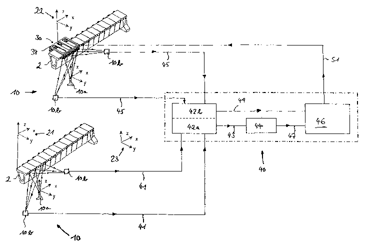
Figure 4 shows a schematic view of the method
course.
The invention is described by way of example using
the machining of construction modules of a hybrid carrier
system for rail-bound vehicles. Such a carrier system is
described in detail in EP 0 987 370 Al, the disclosed
content of which is included herewith.
Figure 1 shows a roadway for a magnetic suspended
railway 100 in section. Carriers 2 consisting preferably of
pre-stressed concrete are fastened to the construction site
on supports 5. Several carriers 2 are set up in series in
the direction of travel of the roadway. Connecting consoles
1 consisting .preferably of steel are arranged laterally on
each carrier 2 at the same interval. Each connecting
console 1 is welded or screwed to an anchoring rod 6 (see
figure 2) for fastening, which is let into the pre-stressed
concrete of carrier 2. Each console 1 comprises a head
plate 4 to which operational plane carriers 3 are attached.
To this end each head plate 4 must be exactly determined and
machined if needed.
CA 02438715 2003-08-19
_ g _
Figure 2 shows a section of a carrier 2 with
connecting consoles 1 fastened to both its sides with the
aid of anchoring rods 6. The actual distance of the two
head surfaces 4 of the two connecting consoles is designated
by Yigt and the required distance by YsoLL. In order to bring
the distance of head surfaces 4 to the required value,
machining device 30 is provided on carrier 2 that has
height-adjustable (see arrows) arms 32 on both sides with
milling heads 33 arranged on their ends. The particular
head surface 4 is machined by moving the particular arm 32
up and down.
Figure 3 shows a schematic front view of an entire
carrier 2 with machining device 30 set on it. Laser 10a of
a determining device 10 is placed at the side of carrier 2
which device determines in independent steps on the one hand
carrier 2 and especially connecting consoles 1 and on the
other hand machining device 30.
The method of the invention for this determination
and optional machining is described in the following using
the schematic view of figure 4. At first, a laser 10a is
placed as part of determining device 10 in front of
stationary carrier 2, on account of its size and weight, and
determines carrier 2 or a carrier section. The laser beams
shown in the form of straight lines 11 with arrowheads are
reflected on carrier 2 and pass to one or more measuring
elements 10b, e.g., measuring sensors, whose measuring
signals are conducted further via lines 41 to calculating
unit 42a of computer 40 in order to determine the shape and
the position of carrier 2 and of connecting consoles 1, that
is, of the workpiece from the running time and the direction
of the returning laser beams.
It is particularly known that spheres and partial
spheres that have a small diameter in comparison to the
surface to be determined can be arranged at defined
positions of the surface in order to obtain statements about
CA 02438715 2003-08-19
- 10 -
the course of the surface from the beams reflected from the
sphere surface. These spheres or partial spheres are not
shown in figure 4.
In such a determining step, e.g., an accuracy of
approximately 0.5 mm is achieved in the three spatial
directions. In order to assure the required tolerances in
any subsequent machining a second partial determining step
can be performed. For this, a partial range of the
previously measured carrier section is determined,
l0 preferably with the same determining device 10. This step
is not shown in figure 4. For example, an accuracy of
determination of approximately Q.03 mm can be achieved with
the above. The actual space curve of carrier 2 is
calculated in a first coordinate system 21 from the measured
signals of the two partial determining steps by calculating
unit 42a, which curve is then transmitted further via line
43 to comparison module 44 in order that it can compare the
actual geometry with the stored theoretical space curve of
carrier 2. This data then serves for the subsequent
machining of head plates 4.
Machining device 30 shown in figures 2, 3 is
provided for this machining and is likewise determined by
determining device 10. The determination data serve in
particular to determine the position of machining device in
a second coordinate system 22 that according to the
invention is independent of the first coordinate system 21.
To this end machining device 30 is set without a
very precise adjustment on carrier 2 since machining device
at first does not require any exact guidance or
30 positioning on account of the functional separation of
coordinate systems 21, 22. Machining device 30 is
subsequently determined by determining device 10. The same
measuring elements lOb are preferably used to this end as
for the determining of carrier 2, that then pass the
CA 02438715 2003-08-19
- 11 -
measured signals on via lines 45 to calculating unit 42b of
computer 40.
Machining device 30 shown in figures 2 to 4 is set
on carrier 2. In this embodiment machining device 30 has a
frame 34 (Figure 4) extending over the distance of several
head plates 4. Several machining units with milling heads
33 shown in figures 2, 3 are arranged opposite head plates 4
and staggered on frame 34 in the longitudinal direction of
carrier 2, that assume the machining of a head plate 4. As
a result, the machining of head plates 4 of carrier 2 can
take place in sections, during which the machining
advantageously takes place simultaneously on both sides of
the carrier.
After the machining of a section with several head
plates 4, frame 34 is shifted into the next section to be
machined, machining unit 30 or the machining units are
determined and the machining is subsequently carried out.
In an alternative embodiment of the invention (not
shown) machining device 30 or the machining devices can also
be arranged, e.g., on a gantry crane or the like that can
move along carrier 2 and makes no contact with carrier 2.
It is advantageous if machining device 30 is
repeatedly determined during the machining of head plates 4.
This can take place in a step-by-step manner or also
continuously. This procedure permits a constant checking of
the progress of the machining and of the adjusting of
machining device 30.
In order to be able to give machining device 30
the necessary machining commands the determination data of
determining device 10 and the determination data of
machining device 30 must be brought into a relationship with
each other. This means that the first and the second
coordinate systems 21, 22 must be correlated. To this end
the particular signals and data records are fed via lines
47, 49 into calculating unit 46 of computer 40 where the
CA 02438715 2003-08-19
- 12 -
spatial relationships between carrier 2 and machining device
30 are created and machining commands are derived from them
that are passed on via line 51 to machining device 30. In
such a machining step in particular the corresponding
surfaces of head plates 4 are milled for an accurately
fitting mounting of operational plane carriers 3.
In order to produce the correlation of first and
of second coordinate systems 21, 22 a transformation of
coordinates from the one coordinate system into the other
one can be carried out . In order to make this possible it
must be assured that the position of laser 10a in space is
known, that is, its position must be calibrated. The
opportunity presents itself here that beams emitted from
laser 1.0a are received directly by receivers lOb and are
evaluated by calculating units 42a, 42b (these direct beams
are not sketched in Figure 4 for the sake of clarity). The
position of determining device 10 in space can then be
determined and the desired transformation of coordinates
carried out.
As an alternative, the first and the second
coordinate system 21, 22 are brought into a relationship in
a third, global (that is, spatially fixed) coordinate system
23 and the commands for machining workpiece 1, 2 are
generated in this latter coordinate system. It is also
necessary for this to determine and calibrate determining
device 10 in space, advantageously in the same manner as
described above.
Determining device 10 is advantageously designed
to be mobile, which is particularly advantageous when
determining in several partial steps. In order to achieve,
e.g., the finer resolution in the above-mentioned second
partial determining step for a section of carrier 2,
determining device 10 is placed closer to carrier 2.
Determining device 10 can be positioned elsewhere even
CA 02438715 2003-08-19
- 13 -
during the machining of head plates 4 in order to take into
account the movement of machining device 30.
Determining device 10 can also be coupled or
fastened with advantage to machining device 30.
Instead of the above-described machining with a
machining device a measuring by an appropriately designed
measuring device (not shown) is also possible using the
method of the invention. For example, the temperature,
color, electrical magnitudes, surface structures, etc. can
be measured.
The invention can be used during the determining
and during the measuring andjor machining of a stationary
workpiece or of a moving workpiece. In the latter variant a
multiple determining of the workpiece is advantageous.