Note: Descriptions are shown in the official language in which they were submitted.
CA 02438855 2003-08-20
WO 02/067749 PCT/GB02/00613
1
A Cleanim Head for a Vacuum Cleaner
This invention relates to a cleaning head for a vacuum cleaner and to a vacuum
cleaner
including such a cleaning head.
Upright vacuum cleaners, such as the one shown in Figure 1, are well known and
include a cleaning head having a motor or air driven brush bar for agitating a
floor
covering. Such vacuum cleaners are efficient at cleaning those parts of a room
which
are spaced from the very edge of a room. The vacuum cleaner is pushed
backwards a
and forwards across a surface so as to agitate the surface. A motor-driven fan
in the
cleaner `sucks' the dislodged dirt and dust from the region beneath the
cleaning head
and conveys it to a separating and collecting unit on the cleaner. It is known
that dirt,
dust and other debris can collect at the very edge of a floor surface,
alongside the wall
of the room. Upright vacuum cleaners can be used in an alternative mode of
operation
where, instead of pushing the cleaner across a surface and allowing the brush
bar to
agitate the surface, a user manually directs a hose to those parts of a room
which cannot
be reached by the cleaning head. However, it is time consuming to use the
cleaner in
this way and it is preferable to clean as much dirt as possible from the room
using the
cleaning head. Dyson Limited manufacture a vacuum cleaner with the name DC04TM
which includes a single tuft of bristles on each side of the cleaning head. US
4,219,902
shows a vacuum cleaning head with bristles which project outwardly from the
cleaning
head in a direction which is perpendicular to the side of the cleaning head
and towards
the floor surface. US 4,685,170 shows a floor tool for a vacuum cleaner which
has a
tuft of bristles on each side which are both longer and less stiff than the
other bristles
such that they flex outwardly when the floor tool is in use on a floor
surface.
The present invention seeks to provide a cleaning head for a vacuum cleaner
which has
an improved cleaning performance when used at the edges of a room.
Accordingly, a first aspect of the present invention provides a cleaning head
for a
vacuum cleaner comprising a housing which extends transversely to the
direction of
CA 02438855 2009-05-27
2
intended movement of the head and a continuous row of bristles, the bristles
extending
tiansversely outwardly and forwardly from at least one of the sides of the
housing and
extending to a level beneath the lowermost surface of the housing.
A cleaning head of this IQnd has the advantage that dirt, dust and other
debris which
coliects at the very edge of a room is either 'guided' out of the region .next
to the wall or
is subjected to a vigorous `flicking' action as the head is moved across the
floor.
The cleaning perfoimsnce of the head is further improved by pr+ovidistg a
suction
channel adjacent to the bristles, the suction channel extending between the
outer edge of
the housing to a suction space within the housing. Thus, any dirt, dust and
debris which
is guided or `flicked' out from the region adjacent the wall is more likely to
be carried
towards the collector on the vacuum cleaner by the fast flowing stream of air
adjacent
the row of bristles.
Preferably the bristles are removably held in the housing. Ibis has the
advantage that
they can be easily replaced when they become wom or damaged_
A further aspect of the invention provid.es a vacuum cleaner incorporating a
cleaning
head of the 3dnd described above.
According to an aspect of the present invention there is provided a cleaning
head for a
vacuum cleaner, the cleaning head comprising:
a housing with, two opposite sides, such that the housing extends transversely
relative to
a direction of intended movement of the head while in use between the opposite
sides;
and
a continaous row of bristles mounted on at least one of the two opposite
sides,
extending transversely outwardly and forwardly relative to the direction of
intended
movement of the cleaning head while in use from the at least one of the two
opposite
sides of the housing and extending to a level beneath the lowermost surface of
the
housing,
CA 02438855 2009-05-27
2a
wherein the housing has a suction channel forrned therein that extends from an
outer
edge of the housing to a suction space within the housing and has an inlet on
a leading
edge of the housing that lies adjacent to and inwardly of the row of bristles,
the suction
channel being located adjacent to and extencling paralIel to the row of
bristles.
According to another aspect of the present invention there is provided_a
vacuum cleaner,
comprisirng:
a body having an external surface;
a suction intet on the body for conveying dirty air from outside the vacuum
cleaner into
the body;
a motor configured to draw the dirty air into the body throug2i the suction
inlet;
a cleaning head including a housing with two opposite sides, such that the
housing
extends transversely relative to a direction of intended movement of the head
between the
opposite sides; and
a continuous row of bristles mounted on at least one of the two opposite
sides,
extending transversely outwardly and forwardly relative to the direction of
intended
movement of the cleaning head while in use from the at ieast one of the two
opposite
sides of the housing and extending to a level beneath the lowermost surface of
the
housing,
wherein the housing has a suction channel formed therein that extends from an
outer
edge of the housing to a suction space within the housing and has a fiirther
inlet on a
leading edge of the housing that lies adjacent to and inwardly of the row of
bristles, the
suction channel extending parallel to the row of bristles.
.F.mbodiments of the inventiori wlll,now .be desarebed, by way af example
only, with
reference to the accompanying drawings in which:
Figure 1 shows a known type of upright vacuum cleaner on which the cleaning
bead can
be used;
Figure 2-5 show an improved cleaning head for the cleaner of Figeire 1; and,
Fignre 6 shows the cleaning head of Figures 2-5 in use on a floor surface.
CA 02438855 2009-06-30
3
Figure 1 shows a vacuum cleaner 10 having a main chassis 50 which supports
dirt and
dust separation apparatus 20. The lower part of the cleaner 10 comprises a
cleaning
head 30 for engaging with the floor surface. The cleaning head has a
downwardly
facing suction inlet and a brush bar is mounted in-the mouth of the inlet for
agitating the
floor surface. The cleaning head is pivotably mounted to a motor housing 24
which
houses the motor and fan of the cleaner. Support wheels 26 are mounted to the
motor
housing for supporting the cleaner and allowing movement across a floor
surface. A
spine of the chassis 50 extends upwardly from the motor housing 24 to provide
support
for the components of the cleaner. A cleaning wand 42 having a second dirty
air inlet
43 is connected by way of a hose (not shown) to the chassis at the base of the
spine 50.
The wand 42 is releasable from the spine 50 so as to allow a user to caiTy out
above-the-
floor cleaning and cleaning in places which are inaccessible by the main
cleaning head
30. When the wand is fixed to the spine 50, the wand 42 forms the handle of
the cleaner
and a handgrip 40 at the remote end of the wand 42 allows a user to manoeuvre
the
cleaner. These features of the cleaner are well known and have been well
documented,
for example, in other cleaners which are manufactured by Dyson Limited, and
will not
be described in any further detail.
Dirty air from the cleaning head 30 or wand inlet 43 is carried to the
separator unit 20
by an inlet conduit (not shown). Separator 20 can be a cyclonic separator
which spins
dirt, dust and other debris out of the airflow by centrifugal separation as
described more
fully in EP 0 042 723, or the separator can be a conventional filter bag.
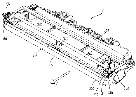
Figures 2 -5 show a cleaning head 30 for use with the vacuum cleaner of Figure
1. As
seen in Figure 2, cleaning head 30 comprises a housing 305 with an outlet 32
for
connectg _lg to the chassis of the vacuum cleaner. A flexible tube (not show :-
,ets
.the outlet 32 to a conduit on the chassis which leads to the separator unit
20. The
cleaning head housing 305 comprises a front poi-tion 301 which extends
laterally across
the width of the vacuum cleaner 100, transversely to the direction of movement
of the
cleaner and two rearwardly extending sides 302, 303. A lug 340 extends
outwardly
CA 02438855 2003-08-20
WO 02/067749 PCT/GB02/00613
4
from each side 302, 303. Support arms (315, Figure 1) support the cleaning
head via
these lugs 340 and allow the cleaning head 30 to pivot about the lugs.
The cleaning head 30 has an upper plate 351 and a lower plate 352 which may be
made
from plastics material or a metal such as stainless steel. The upper and lower
plates
351, 352 are joined together by quarter turn fasteners (not shown), by press-
fitting or by
other suitable means. A seal 353 is trapped between the upper and lower plates
351,
352 so as to ensure that the seal between the plates 351, 352 is essentially
airtight.
Rollers 356 are rotatably mounted at the front edge of the lower plate 352 to
support the
cleaning head on the carpet or other surface to be cleaned. The rollers 356
can be
positioned at or adjacent the outer edges of the lower surface or,
alternatively, can either
extend continuously or in a spaced manner across the entire width of the lower
plate
352.
A suction opening 320, 321, 322 is formed in the lower plate 352. The suction
opening
extends across the entire width of the brush housing 305. A brush bar (not
shown) is
rotatably mounted in the housing 305 so that the bristles of the brush bar
protrude
slightly out of the suction opening 320, 321, 322. The brush bar is arranged
to be
drivable by the motor of the vacuum cleaner 100 in a conventional manner, for
example,
by way of a drive belt which enters the head via channel 370 in the upper
plate 351 of
the head.
A row of bristles 310 are mounted on each side of the lower plate 352 of the
cleaning
head. The bristles 310 are held together by a u-shaped metal clip which is
crimped
around one end of each tuft of the bristles. Thus, the row of bristles are a
single part.
The bristles 310 are supported in a rearwardly extending channe1309 in the
lower plate
352 of the cleaning head. The bristles 310 are held within the channe1309 by a
lip 311
on the forward portion of the upper plate 351. The bristles can be easily
removed and
replaced by separating the upper and lower plates 351, 352 of the head. The
bristles 310
can then be slid out of the open end of the channe1309.
CA 02438855 2009-06-30
The bristles 310 are supported such that they project in a direction which is
both
diagonally outwardly and forwardly from the bottom corner of the cleaning
head. The
length of the bristles is such that the distal end of the bristles project
beyond the side of
the cleaning head 30 (see Figure 4) and below the lower surface of the
cleaning head.
5 The bristles are sufficiently firm that they will provide an effective
`flicking' action on
dirt when used for edge of the room cleaning. The bristles are also
sufficiently flexible
that they will not unnecessarily wear the floor surface when they are used
away from
the edge of the room. A suction channel 330 lies directly beside the bristles
310. The
suction channel 330 extends rearwardly from the leading edge of the cleaning
head.
The suction channel 330 has a chamfered edge 312 which serves to guide dirt
and dust
towards the suction channel 330. The suction channel 330 provides a flow of
fast-
moving air adjacent to the bristles to ensure that dislodged dirt and dust
will be carried
into the cleaning head 30.
Figure 6 shows the cleaning head 30 in use on a carpeted floor. Figure 6 shows
the
region of the room directly adjacent a wall 410 of a room. The floor 400 is
covered by
an underlay material 401. A gripper board 403 lies between the edge of the
underlay
401 and the skirting board 404. Carpet 402 overlies the underlay 401 and
gripper board
403 and projects downwardly towards the floor 400 in the region next to the
skirting
board 404. It can be seen that dirt and dust readily accumulates in region 420
which lies
below the level of the remainder of the carpet.
Bristles 310 on the side of the cleaning head 30 project into region 420.
Because the
bristles are directed forwardly, dirt, dust and other debris is prised out of
region 420 and
will either `ride' up the leading edge of the row of bristles or will be
flicked into the
room (in a direction away from the wall 410). Thus, dirt is either guided
towards the
suction channel 330 or is moved to a different position where there is a much
greater
lilcelihood of it being successfully picked up. A good flow of air should be
drawn into
the cleaning head housing via suction channels 330. The dirt and dust which
has been
prised out of the edge region and towards suction channel 330 will be carried
into the
CA 02438855 2003-08-20
WO 02/067749 PCT/GB02/00613
6
cleaning head housing as part of this airflow or via the other suction inlets
320, 321,
322.