Note: Descriptions are shown in the official language in which they were submitted.
CA 02439084 2003-08-20
WO 02/075936 PCT/US02/07941
1
SYSTEM AND METHOD FOR
WIDE BAND R_AMAN AMPLIFICATION
TECHNICAL FIELD OF THE INVENTION
The present invention relates to the field of
communication systems, and more particularly to a system and
method operable to facilitate wide band optical
amplification while maintaining acceptable noise figures.
BACKGROUND OF THE INVENTION
Because of the increase in data intensive applications,
the demand for bandwidth in communications has been growing
tremendously. In response,. the installed capacity of
telecommunication systems has been increasing by an order of
magnitude every three to four years since the mid 1970s.
Much of this capacity increase has been supplied by optical
fibers that provide a four-order-of-magnitude bandwidth
enhancement over twisted-pair copper wires.
To exploit the bandwidth of optical fibers, two key
technologies have been developed and used in the
telecommunication industry: optical amplifiers and
wavelength-division multiplexing (WDM). Optical amplifiers
boost the signal strength and compensate for inherent fiber
loss and other splitting and insertion losses. WDM enables
different wavelengths of light to carry different signals in
parallel over the same optical fiber. Although WDM is
critical in that it allows utilization of a major fraction
of the fiber bandwidth, it would not be cost-effective
without optical amplifiers. Tn particular, broadband optical
amplifier systems that permit simultaneous amplification of
many WDM channels are a key enabler for utilizing the full
fiber bandwidth.
CA 02439084 2003-08-20
WO 02/075936 PCT/US02/07941
2
Traditionally, amplification of signals having a broad
range of wavelengths has required separating the signals
into subsets of wavelengths, and amplifying each subset with
a separate amplifier. This approach can be complex and
expensive. Using separate amplifiers for each subset
requires additional hardware, additional laser pumps for
each amplifier, and additional power to launch the
additional pumps.
Although a more efficient approach would be to amplify
the entire signal using a single amplifier for at least some
amplifiers in the system, unfortunately, no acceptable
single amplifier approach has been developed. For example,
erbium doped-amplifiers are an inherently bad choice for
wide band amplification if the ultimate goal is to provide
an amplifier that can operate over the entire
telecommunications spectrum. For example, for wavelengths
shorter than about 1525 nanometers, erbium-atoms in typical
glasses will absorb more than they amplify. Even with use
of various dopings, such as, aluminum or phosphorus, the
absorption peak for the various glasses is still around 1530
nanometers. This leaves a large gap in the short
communications band (S-Band) unreachable by erbium doped
fiber amplifiers.
Raman amplifiers provide a better solution in terms of
broadband amplification potential, but conventional Raman
amplifiers have suffered from other shortcomings. For
example, Raman amplifiers have traditionally suffered from
high noise figures when used in wide band applications. In
addition, Raman amplifiers suffer from gain tilt introduced
when longer wavelength signals rob energy from shorter
wavelength signals. This effect becomes increasingly
f
pronounced as amplifier launch power and system bandwidth
CA 02439084 2003-08-20
WO 02/075936 PCT/US02/07941
3
increases. Wide band Raman amplifiers operating at high
launch powers on a wide range of wavelengths can be
particularly vulnerable to this effect.
Masuda, et al. (see e.g., United States Patent Number
6,172,803 B1 and related research papers) have attempted to
improve the bandwidth of erbium doped amplifiers by
cascading with the erbium doped amplifier a Raman amplifier
with an approximately complementary gain profile. Masuda,
et al, however, consistently require the presence of an
erbium doped amplifier (which relies on different physics
for amplification and does not suffer from the same noise
problems as Raman amplifiers do) to provide virtually all
amplification to signal wavelengths close in spectrum to the
pump wavelengths. Indeed, Masuda, et al. concede that the
noise figures they report ignore the effect of the Raman
portion of their amplifier.
SUMMARY OF THE INVENTION
The present invention recognizes a need for a method
and apparatus operable to facilitate wide band Raman
amplification while maintaining an approximately flat gain
profile and an acceptable noise figure.
In accordance with the present invention, a system and
method for providing wide band Raman amplification are
provided that substantially reduce or eliminate at least
some of the shortcomings associated with prior approaches.
In one aspect of the invention, a multi-stage Raman
amplifier comprises a first Raman amplifier stage having a
first sloped gain profile operable to amplify a plurality of
signal wavelengths, and a second Raman amplifier stage
having a second sloped gain profile operable to amplify at
least most of the plurality of signal wavelengths after
CA 02439084 2003-08-20
WO 02/075936 PCT/US02/07941
4
those wavelengths have been amplified by the first stage.
The second sloped gain profile has an approximately
complementary slope to the slope of the first sloped gain
profile. The combined effect of the first and second Raman
stages contributes to an approximately flat overall gain
profile over the, plurality of signal wavelengths.
In another aspect of the invention, a method of
amplifying an optical signal having multiple wavelengths
comprises amplifying a plurality of signal wavelengths at a
first Raman amplifier stage having a first sloped gain
profile, and amplifying at least most of the plurality of
signal wavelengths at a second Raman amplifier stage after
those signal wavelengths have been amplified by the first
stage. The second stage has a second sloped gain profile
comprising an approximately complimentary gain profile to
the first gain profile. The combined effect of the first
and second Raman stages contributes to an approximately flat
overall gain profile over the plurality of signal
wavelengths.
Tn st,ill another aspect of the invention, a multi-stage
Raman amplifier comprises a plurality of cascaded Raman
amplifier stages each having a gain profile, wherein the
gain profile of at least some of the Raman stages is sloped.
At least two of the sloped gain profiles comprise
approximately complimentary gain profiles, wherein the
combined effect of the gain profiles of the amplification
stages results in an approximately flat overall gain profile
over a plurality of signal wavelengths amplified by the
amplifier.
Tn yet another aspect of the invention, a method of
amplifying multiple-wavelength optical signals comprises
applying a first sloped gain profile to a plurality of
CA 02439084 2003-08-20
WO 02/075936 PCT/US02/07941
signal wavelengths at a first stage of a Raman amplifier,
and applying a second sloped gain profile to at least most
of the plurality of signal wavelengths at a second stage of
the Raman amplifier. The second gain profile comprises an
5 approximately complementary gain profile of the first sloped
gain profile. The combined effect of the first and second
sloped gain profiles contributes to an approximately flat
overall gain profile over the plurality of signal
wavelengths.
In another aspect of the invention, a multi-stage Raman
amplifier comprises a plurality of cascaded Raman amplifier
stages each operable to amplify a plurality of signal
wavelengths and each having a gain profile determined at
least in part by one or more pump wavelengths applied to the
amplifier stage. The plurality of amplifier stages comprise
a first Raman stage operable to apply a higher gain level to
a signal wavelength. closest to a longest pump wavelength
than a gain applied to a signal wavelength furthest from the
longest pump wavelength.
In still another aspect of the invention, a method of
amplifying an optical signal having multiple wavelengths
comprises receiving a plurality of signal wavelengths at a
plurality of cascaded Raman amplifier stages having at least
a first stage and a last stage, where each stage is operable
to amplify a plurality of signal wavelengths and each stage
has a gain profile determined at least in part by one or
more pump wavelengths applied to the amplifier stage. The
method further includes applying a highest level of gain
supplied by the longest pump wavelength in the last Raman
stage of the amplifier.
In yet another aspect of the invention, a multi-stage
Raman amplifier comprises a plurality of cascaded Raman
CA 02439084 2003-08-20
WO 02/075936 PCT/US02/07941
6
amplifier stages, at least some of the Raman stages having
sloped gain profiles operable to contribute to a combined
gain profile of the amplifier. The combined gain profile of
the amplifier is approximately flat across a bandwidth of at
least eighty nanometers and comprises a small signal noise
figure no greater than eight decibels.
In another aspect of the invention, a method of
amplifying an optical signal having multiple wavelengths
comprises amplifying a plurality of signal wavelengths at a
first Raman amplifier stage having a first sloped gain
profile, and amplifying at least most of the plurality of
signal wavelengths at a second Raman amplifier stage having
a second sloped gain profile that is different than the
first sloped gain profile. The combined gain profile of the
amplifier is approximately flat across a bandwidth of at
least eighty nanometers and comprises a small signal noise
figure no greater than eight decibels.
In another aspect of the invention, an optical pre
amplifier operable to be coupled to an optical communication
link carrying optical signals having a plurality of
wavelengths comprises a first Raman stage having a gain
profile where a majority of shorter signal wavelengths are
amplified more than a majority of longer signal wavelengths.
The preamplifier further comprises a second Raman stage
operable to receive at least most of the signal wavelengths
after they have been amplified by the first stage, the
second stage having a gain profile where a majority of
longer signal wavelengths are amplified more than a majority
of shorter signal wavelengths. In this embodiment, the gain
profiles of the first and second Raman stages are operable
to combine to contribute to an approximately flat combined
gain profile over the plurality of signal wavelengths.
CA 02439084 2003-08-20
WO 02/075936 PCT/US02/07941
7
In still another aspect of the invention, an optical
booster amplifier operable to be coupled to an optical
communication link carrying optical signals having a
plurality of wavelengths comprises a first Raman stage
having a gain profile where a majority of longer signal
wavelengths are amplified more than a majority of shorter
signal wavelengths. The booster amplifier also comprises a
second Raman stage operable to receive at least most of the
signal wavelengths after they have been amplified by the
first stage, the second stage having a gain profile where a
majority of shorter signal wavelengths are amplified more
than a majority of longer signal wavelengths. The gain
profiles of the first and second Raman stages are operable
to combine to contribute to an approximately flat combined
gain profile over the plurality of wavelengths.
In yet another aspect of the invention, a Raman
amplifier assembly comprises a preamplifier coupled to an
optical communication link. The preamplifier includes a
first Raman stage having a gain profile wherein a majority
of shorter wavelengths are amplified more than a majority of
longer wavelengths, and a second Raman stage having a gain
profile approximately complementary to the first gain stage.
The amplifier assembly also includes a booster amplifier
coupled to the optical communication link. The booster
amplifier comprises a first Raman stage having a gain
profile wherein a majority of longer wavelengths are
amplified more than a majority of shorter wavelengths, and a
second Raman stage having a gain profile approximately
complementary to the first gain stage.
In another aspect of the invention, an optical
communication system operable to facilitate communication of
multiple signal wavelengths comprises a transmitter bank
CA 02439084 2003-08-20
WO 02/075936 PCT/US02/07941
8
operable to generate a plurality of signal wavelengths, and
a multiplexer operable to combine the plurality of signal
wavelengths into a single multiple wavelength signal for
transmission over a transmission medium. The system further
comprises an amplifier coupled to the transmission medium
and operable to amplify the multiple wavelength signal prior
to, during, or after the multiple wavelength signal s
transmission over the transmission medium, the amplifier
comprising a multi-stage Raman amplifier. The amplifier
includes a first Raman amplifier stage having a first sloped
gain profile operable to amplify a plurality of signal
wavelengths and a second Raman amplifier stage having a
second sloped gain profile operable to amplify at least most
of the plurality of signal wavelengths after those
wavelengths have been amplified by the first stage. The
second sloped gain profile has an approximately
complementary slope to the slope of the first sloped gain
profile, and the combined effect of the first and second
Raman stages contributes to an approximately flat overall
gain profile over the plurality of signal wavelengths. In
one embodiment, the system further includes a demultiplexer
operable to receive the multiple wavelength signal and to
separate the signal wavelengths from the multiple wavelength
signal, and a receiver bank operable to receive the
plurality of signal wavelengths.
Depending on the specific features implemented,
particular embodiments of the present invention may exhibit
some, none, or all of the following technical advantages.
For example, one aspect of the invention facilitates optical
amplification of a wide bandwidth of wavelengths while
maintaining an approximately flat gain profile and an
acceptable noise figure.
CA 02439084 2003-08-20
WO 02/075936 PCT/US02/07941
9
In a particular embodiment, one aspect of the invention
reduces the noise figure associated with the amplifier by
amplifying in a first Raman stage a majority of shorter
wavelengths more than a majority of longer wavelengths. In
this way, shorter wavelengths (which are often closest to
the pump wavelength) are amplified to overcome any effects
that might be caused by phonon-stimulated noise. As a
further enhancement, the amplifier could be designed so that
the longest pump wavelength is at least ten manometers below
the shortest signal being amplified.
In addition to yielding an acceptable noise figure,
this approach can produce an approximately flat gain tilt,
for example, by cascading a second Raman amplifier stage
having a gain profile that amplifies a majority of longer
wavelengths more than a majority of shorter wavelengths. In
a particular embodiment, the second gain profile can be
approximately complementary to the first gain profile. In
some applications, the second gain profile can have an
approximately equal (although opposite) slope from the first
gain profile.
Another aspect of the invention results in increased
efficiency in a mufti-stage Raman amplifier. This aspect of
the invention involves applying, in at least one Raman
stage, a first gain profile that amplifies a majority of
longer wavelengths more than a majority of shorter
wavelengths; and applying, in a later cascaded Raman stage,
a second gain profile that amplifies a majority of shorter
wavelengths more than a majority of longer wavelengths.
This embodiment facilitates allowing longer pump wavelengths
in the first stage to accept energy from shorter pump
wavelengths in the later Raman stage. This effect, in turn,
facilitates using smaller pump wavelengths and/or fewer pump
CA 02439084 2003-08-20
WO 02/075936 PCT/US02/07941
wavelengths in the first stage than would otherwise be
required, .thereby increasing the efficiency of the device.
In a particular embodiment, the gain profiles of the first
and later Raman stages can be approximately complimentary,
5 contributing to an approximately flat overall gain profile
for the amplifier. The noise figure can be reduced, for
example, by performing a majority of the amplification of
wavelengths closest to the pump wavelengths in one of the
final amplifier stages, or in the last amplifier stage.
10 Other aspects of the invention facilitate cascading
multiple amplifier stages to realize advantages of low noise
and high efficiency in a multiple stage Raman amplifier.
Moreover, cascaded stages can provide mid-stage access to
the amplifier to facilitate, for example, optical add/drop
multiplexing of WDM signals while maintaining an acceptable
noise figure and an approximately flat gain profile, both at
the mid-stage access point and across the entire amplifier.
Other technical advantages are readily apparent to one
of skill in the art from the attached figures, description,
and claims.
BRIEF DESCRIPTION OF THE DRAWINGS
For a more complete understanding of the present
invention, and for further features and advantages thereof,
reference is now made to the following description taken in
conjunction with the accompanying drawings, in which:
FIGURE 1 is a block diagram showing an exemplary
optical communication system operable to facilitate
communication of wide band optical signals constructed
according to the teachings of the present invention;
FIGURE 2 is a graphical illustration of the
phonon-stimulated optical noise figure;
CA 02439084 2003-08-20
WO 02/075936 PCT/US02/07941
11
FIGURE 3a is a block diagram of an exemplary embodiment
of a multiple stage Raman amplifier constructed according to
the teachings of the present invention;
FIGURE 3b-3c show gain profiles associated with various
amplification stages and an overall gain profile for the
amplifier shown in FIGURE 3a, respectively, constructed
according to the teachings of the present invention;
FIGURE 4a is a block diagram of an exemplary embodiment
of a multiple stage Raman amplifier constructed according to
the teachings of the present invention;
FIGURES 4b-4c show gain profiles associated with
various amplification stages and an overall gain profile for
the amplifier shown in FIGURE 4a, respectively, constructed
according to the teachings of the present invention;
FIGURE 5a is a block diagram of an exemplary embodiment
of a three stage Raman amplifier constructed according to
the teachings of the present invention;
FIGURES 5b-5c show gain profiles associated with
various amplification stages and an overall gain profile for
the amplifier shown in FIGURE 5a, respectively, constructed
according to the teachings of the present invention;
FIGURES 6a is a block diagram of an exemplary
embodiment of a four stage Raman amplifier constructed
according to the teachings of the present invention;
FIGURES 6b-6c show gain profiles associated with
various amplification stages and an overall gain profile fox
the amplifier of FIGURE 6a, respectively, constructed
according to the teachings of the present invention;
FIGURE 7 is a flow chart illustrating one example of a
method of amplifying a plurality of wavelengths using a
multi-stage Raman amplifier according to the teachings of
the present invention;
CA 02439084 2003-08-20
WO 02/075936 PCT/US02/07941
12
FIGURES 8a-8b show simulated gain and noise profiles
for one embodiment of a multi-stage hybrid Raman amplifier
constructed according to the teachings of the present
invention; and
FIGURES 9a-9b show simulated gain and noise profiles
for one embodiment of a mufti-stage discrete Raman amplifier
constructed according to the teachings of the present
invention.
DETAILED DESCRIPTION OF THE INVENTION
FIGURE 1 is a block diagram showing an exemplary
optical communication system 10 operable to facilitate
communication of wide band optical signals. System 10
includes a transmitter bank 12 operable to generate a
plurality of wavelength signals 16a-16n. Transmitter bank
12 may include, for example, a plurality of laser diodes or
semiconductor lasers. Each wavelength signal 16a-16n
comprises at least one wavelength of light unique from
wavelengths carried by other signals 16.
System 10 also includes a Combines 14 operable to
receive multiple signal wavelengths 16a-16n and to combine
those signal wavelengths into a single multiple wavelength
signal 16. As one particular example, Combines 14 could
comprise a wavelength division multiplexes (WDM). The term
wavelength division multiplexes as used herein may include
conventional wavelength division multiplexers or dense
wavelength division multiplexers.
In one particular embodiment, system 10 may include a
booster amplifier 18 operable to receive and amplify
wavelengths of signal 16a prior to communication over a
transmission medium 20. Transmission medium 20 can comprise
multiple spans 20a-20n of fiber. As particular examples,
CA 02439084 2003-08-20
WO 02/075936 PCT/US02/07941
13
fiber spans 20 could comprise standard single mode fiber
(SMF), dispersion-shifted fiber (DSF), non-zero
dispersion-shifted fiber (NZDSF), or other fiber type or
combinations of fiber types.
Where communication system 10 includes a plurality of
fiber spans 20a-20n, system 10 can include one or more
inline amplifiers 22a-22m. Inline amplifiers 22 reside
between fiber spans 20 and operate to amplify signal 16 as
it traverses fiber 20:
Optical communication system 10 can also include a
preamplifier 24 operable to receive signal 16 from a final
fiber span 20n and to amplify signal 16 prior to passing
that signal to a separator 26. Separator 26 may comprise,
for example, a wavelength division demultiplexer (WDM),
which can operate on wavelength division multiplexed signals
or dense wavelength division multiplexed signals. Separator
26 operates to separate individual wavelength signals 26a
16n from multiple wavelength signal 16. Separator 26
communicates individual signal wavelength 16a-16n to a bank
of receivers 28.
At least one amplifier in system 10 comprises a wide
band multi-stage Raman amplifier operable to receive a wide
bandwidth of wavelength signal 16. In a particular
embodiment, the amplifier can process over 80 nanometers of
bandwidth, and in some cases over 100 nanometers of
bandwidth while maintaining an approximately flat gain
profile over the bandwidth of amplified signal wavelengths
16.
Throughout this document, the term "approximately flat"
describes a condition where the maximum signal gain differs
from the minimum signal gain by an no more than amount
suitable for use in telecommunication systems. The
CA 02439084 2003-08-20
WO 02/075936 PCT/US02/07941
14
deviation between minimum and maximum signal gains may
comprise, for example five decibels prior to application of
any gain flattening filters. Particular embodiments of the
invention may achieve gain flatness of approximately three
decibels prior to application of any gain flattening
filters.
Some amplifiers in system 10 could comprise a plurality
of individual amplifiers working in conjunction, each
amplifying a subset of the bandwidth processed by the single
wide band amplifier. Alternatively, all amplifiers in
system 10 could comprises wide bandwidth amplifiers.
Depending on the overall bandwidth communicated by system
10, one or more amplifier locations in system 10 could
comprise a plurality of wide band amplifiers operating in
conjunction to handle a total bandwidth significantly in
excess of 100 nanometers. In other cases, a single wide
band amplifier could process all traffic at a given location
in system 10.
Wide band amplifiers within system 10 comprise
mufti-stage Raman amplifiers having at least two stages with
approximately complimentary gain profiles. A combination of
the complimentary gain profiles, in cooperation with any
other gain stages in the wide band amplifier, results in
approximately flat gain profile for the amplifier.
Throughout this description, the phrase "approximately
complementary" refers to a situation where, at least in
general, signal wavelengths 116 that are highly amplified in
the first stage are less amplified in the second stage, and
signal wavelengths 116 that are highly amplified in the
second stage are less amplified in the first stage. Two
gain profiles said to be "approximately complementary" need
not have equal and opposite slopes. Moreover, equal
CA 02439084 2003-08-20
WO 02/075936 PCT/US02/07941
amplification of any particular wavelengths in both gain
profiles does preclude those gain profiles from being
"approximately complementary."
Conventional designs of mufti-stage Raman amplifiers
5 have been unable to process bandwidths in excess of 80
nanometers while maintaining approximately flat gain
profiles and acceptable noise figures. One aspect of this
invention recognizes that a major culprit in noise figures
associated with. conventional mufti-stage Raman amplifiers is
10 the phonon-stimulated optical noise created when wavelength
signals being amplified reside spectrally close to pump
wavelengths used for amplification. One aspect of the
invention reduces adverse effect of this noise by enhancing
the Raman amplification at of signal wavelengths near the
15 pump wavelengths to overcome the effects of the noise, and
applying an approximately complementary Raman gain profile
in another stage to result in an approximately flat overall
gain profile.
FIGURE 2 graphically illustrates the phonon-stimulated
optical noise figure increase as the spectral spacing
between signal wavelengths and pump wavelengths decreases.
As shown in FIGURE 2, phonon-stimulated noise increases
dramatically as signal wavelength get close to the pump
wavelengths.
One aspect of the invention significantly reduces
adverse effects associated with phonon-stimulated noise by
providing multiple stages of Raman gain having approximately
complimentary gain profiles acting on substantially the same
bandwidth of signals. While best results are obtained by
applying approximately complimentary gain profiles to all or
nearly all of the same signal wavelengths, some portion of
wavelengths can be omitted from one gain profile and
CA 02439084 2003-08-20
WO 02/075936 PCT/US02/07941
16
included in the other gain profile without departing from
the scope of this invention.
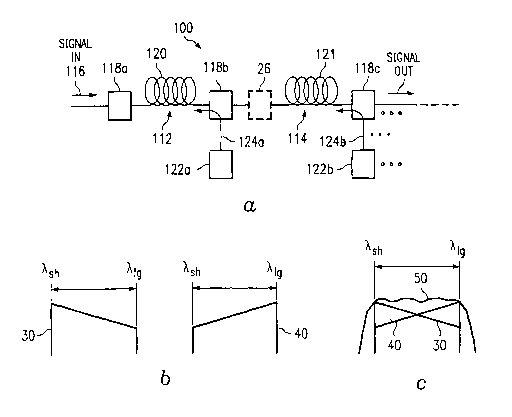
FIGURE 3a is a block diagram of an exemplary embodiment
of a multiple stage Raman amplifier 110 including gain
profiles 30 and 40 associated with various amplification
stages and an overall gain profile 50 for the amplifier. In
this example, amplifier 100 comprises a two-stage amplifier
having a first stage 112 and a second stage 114 cascaded
with first stage 112. As will be further discussed below,
the invention is not limited to a particular number of
amplifier stages. For example, additional amplification
stages could be cascaded onto second stage 114. Moreover,
although the illustrated embodiment shows second stage 114
cascaded directly to first stage 112, additional
amplification stages could reside between first stage 112
and second stage 114 without departing from the scope of the
invention.
Amplifier 100 could comprise a distributed Raman
amplifier, a discrete Raman amplifier, or a hybrid Raman
amplifier which comprises both discrete and distributed
stages. Each stage 112, 114 of amplifier 100 includes an
input operable to receive a multiple wavelength optical
input signal 116. As a particular example, optical input
signal 116 could include wavelengths ranging over one
hundred manometers.
Each stage 112, 114 also includes distributed gain
media 120, 121. Depending on the type of amplifier being
implemented, media 120, 121 may comprise, for example a
transmission fiber, or a gain fiber such. as a spooled gain
fiber. In. a particular embodiment, media 120, 121 may
comprise a dispersion compensating fiber.
CA 02439084 2003-08-20
WO 02/075936 PCT/US02/07941
17
Each stage 112, 114 further includes one or more
wavelength pumps 122. Pumps 122 generate pump light 124 at
specified wavelengths, which are pumped into distributed
gain media 120, 121. Raman gain results from the
interaction of intense light from the pumps with optical
phonons in silica fibers. The Raman effect leads to a
transfer of energy from one optical beam (the pump) to
another optical beam (the signal). Pumps 122 may comprise,
for example, one or more laser diodes. Although the
illustrated embodiment shows the use of counter propagating
pumps, under some circumstances using a relatively quiet
pump, Co-propagating pumps Could also be used without
departing from the scope of the invention.
In one particular embodiment, pump wavelengths 124 can
be selected so that the longest wavelength pump signal 124
has a wavelength that is shorter than the shortest
wavelength of signal 116. As one specific example, the
longest wavelength of pump light 124 could be selected to
be, for example, at least ten nanometers shorter than the
shortest wavelength of signal 116. In this manner,
amplifier 100 can help to avoid. phonon stimulated noise that
otherwise occurs when pump wavelengths interact with
wavelengths of the amplified signal.
Couplers 118b and 118c couple pump wavelengths 124a and
124b to gain distributed media 120 and 121, respectively.
Couplers 118 could comprise, for example, wave division
multiplexers (WDM) or optical couplers. A lossy element 126
can optionally reside between amplifier stages 112 and 114.
Lossy element 126 could comprise, for example, an isolator,
an optical add/drop multiplexes, or a gain equalizer.
The number of pump wavelengths 124, their launch
powers, their spectral and spatial positions with respect to
CA 02439084 2003-08-20
WO 02/075936 PCT/US02/07941
18
other pump wavelengths and other wavelength signals, and the
bandwidth and power level of the signal being amplified can
all contribute to the shape of the gain profile for the
respective amplifier stage. FIGURE 3b shows exemplary gain
profiles for first stage 112 and second stage 114. Gain
profile 30 shows the overall gain of first stage 112 of
amplifier 100 for a bandwidth ranging from the shortest
wavelength of signal 116 (Ash) to the longest wavelength. of
signal 116 (Alg) . Gain profile 40 shows the overall gain of
second stage 112 of amplifier 100 for a bandwidth ranging
from the shortest wavelength of signal 116 (Ash) to the
longest wavelength of signal 116 (Alg). Each of gain
profiles 30 and 40 reflects the effects of the other gain
profile acting upon it.
In this example, gain profile 30 of first stage 112 has
a downward slope, where a majority of the shorter signal
wavelengths 116 are amplified more than a majority of the
longer signal wavelengths 116. Conversely, gain profile 40
of second stage 114 is approximately complimentary to gain
profile 30 of first stage 112. Gain profile 40 exhibits an
upward slope where a majority of the longer signal
wavelengths 116 are amplified more than a majority of the
shorter signal wavelengths 116.
Gain profile 50 (shown in dotted lines in FIGURE 3c)
represents an exemplary composite gain profile .of amplifier
100 resulting from the application of gain profiles 30 and
40 to optical signal 116. Gain profile 50 is approximately
flat over at least substantially all of the bandwidth of
wavelengths~within signal 116.
In operation, amplifier 100 receives optical input
signal 116 at distributive gain medium 120 of first stage
112. Distributed gain medium 120 could comprise, for
CA 02439084 2003-08-20
WO 02/075936 PCT/US02/07941
19
example, a dispersion compensating Raman gain fiber, a
transmission fiber, a high non-linearly fiber, a segment of
transmission fiber, or combination thereof. Pumps 122(a)
generate pump wavelengths 124(a) and apply them to
distributed gain medium 120 through coupler 118(b). Pump
wavelengths 124 interact with signal wavelengths 116,
transferring energy from the pump wavelengths 124 to the
signal wavelengths 116. In this example, shorter signal
wavelengths 116 are amplified more than longer signal
wavelengths 116 in first stage 112.
Amplified wavelengths of signal 116 are communicated to
distributed gain medium 121 of second stage 114.
Wavelengths of signal 116 are amplified in second stage 114
by interacting with pump wavelengths 124b generated at pumps
122b. In this example, pump wavelengths 124b operate to
result in gain profile 40 where longer wavelengths of signal
116 are amplified more than shorter wavelengths of signal
116.
The combined effect of amplification in first stage 112
and second stage 114 of amplifier 100 results in
approximately flat gain profile 50 across wavelengths of
optical signal 116. This particular example provides a
significant advantage in reducing the noise figure
associated with the amplifier. Using this configuration,
the small signal noise figure of amplifier 100 can be
reduced to less than eight decibels, in some cases 7
decibels, even where the bandwidth of signal 16 exceeds 100
nanometers.
FIGURE 4a is a block diagram of another embodiment of a
multiple stage Raman amplifier 110 including exemplary gain
profiles 130 and 140 associated with various amplification
stages and an overall gain profile 150 for the amplifier.
CA 02439084 2003-08-20
WO 02/075936 PCT/US02/07941
Amplifier 110 shown in FIGURE 4 is similar in structure and
function to amplifier 100 shown in FIGURE 1. Like amplifier
100 shown in FIGURE l, amplifier 110 of FIGURE 4 includes a
first Raman amplification stage 112 and a second Raman
5 amplification stage 114. Each of stages 112 and 114
includes a distributed gain medium 120, 121, respectively,
which is operable to receive multiple wavelength input
signal 116 and pump wavelengths 124a and 124b, respectively.
Each amplifier stage 112 and 114 operates to amplify
10 wavelengths of signal 116 according to gain profiles 130 and
140 as shown.
The example shown. in FIGURE 4 differs from the example
shown in FIGURE 3 in that gain profile 130 (shown in FIGURE
4b) of first stage 112 exhibits an upward slope where a
15 majority of longer wavelengths of signal 116 are amplified
more than the majority of shorter wavelengths of signal 116.
Conversely, gain profile 140 of second stage 114 comprises
an approximately complementary gain profile to first gain
profile 130 of first stage 112. In profile 140 applies a
20 higher gain to a majority of shorter wavelengths than the
gain applied to the majority of longer signal wavelengths
116. In addition, in this embodiment, the launch power of
pumps 122a driving first gain profile 130 can be reduced.
This aspect of the invention recognises that due to the
Raman scattering effect, longer wavelength signals tend to
rob energy from shorter wavelength signals. This aspect of
the invention leverages that fact to allow the longer pump
wavelengths of wavelengths 124a to rob energy from the
shorter pump wavelengths of wavelengths 124b. In a
particular embodiment, amplifier 110 may include a shunt 160
between second distributed gain medium 121 and first
distributed gain medium 120 to facilitate the longer pump
CA 02439084 2003-08-20
WO 02/075936 PCT/US02/07941
21
wavelengths of wavelengths 124a accepting power from the
shorter pump wavelengths of wavelengths 124b. The effects
result in an overall gain profile 130 for first stage 112
that remains approximately complimentary to the gain profile
of second stage 140. As a result, the composite gain
profile 150 (FIGURE 4c) of the amplifier remains
approximately flat.
This embodiment provides significant advantages in
terms of efficiency by allowing the use' of fewer wavelength
pumps 122a in the first stage 112, and/or also by allowing
each pump 122a to operate at a lower launch power.
The embodiment shown in FIGURE 4a can also provide
improvements for the noise figure of the amplifier. For
example, phonon stimulated noise is created in Raman
amplifiers where wavelengths being amplified spectrally
reside close to a wavelength of pump signals 124. One
aspect of this invention recognises that by spectrally
separating pump wavelengths 124 from signal wavelengths 116,
phonon stimulated noise can be reduced.
In a particular embodiment, pump wavelengths 124 are
selected to have wavelengths at least 10 nanometers shorter
than the shortest wavelength in optical signal 116 being
amplified. Moreover, in a particular embodiment, second
stage 114 where a majority of the gain to short wavelength
of signal 116 is applied comprises the last stage of
amplifier 110.
FIGURE 5a is a block diagram of a three stage Raman
amplifier 200 including gain profiles 230, 240, and 245
associated with various amplification stages, and an overall
gain profile 250 for the amplifier. Amplifier 200 is
similar in structure and function to amplifier 100 of FIGURE
3 but includes three cascaded amplification stages 212, 214,
CA 02439084 2003-08-20
WO 02/075936 PCT/US02/07941
22
and 215. Each of amplifier stages 212-215 includes a
distributed gain medium 220, 221, 223, respectively, which
operate to receive multiple wavelength optical signal 216
and pump wavelengths 224a-224c from pumps 222a-222c. Each
amplifier stage includes an optical coupler operable to
introduce pump wavelengths 224 to the respective gain media.
In some embodiments, lossy elements 226 may reside between
one or more amplification stages 212-215. Lossy elements
226 may comprise, for example, optical add/drop
multiplexers, isolators, and/or gain equalizers.
Amplifier 200 may comprise a discrete Raman amplifier
or a hybrid Raman amplifier. For example, first distributed
gain medium 220 may comprise a transmission fiber, a section
of transmission fiber, or a Raman gain fiber. In a
particular embodiment, first distributed gain medium 220
could comprise a dispersion compensating Raman gain fiber.
Distributed gain medium 221 of second stage 214 may
comprise a segment of transmission fiber or a Raman gain
fiber. Distributed gain medium 223 of third amplifier phase
215 could comprise, for example, a Raman gain fiber. In
particular embodiments, any or all of distributed gain
mediums 220-223 could comprise a dispersion compensating
Raman gain fiber.
In operation, amplifier 200 receives signal 216 at
first stage 212 and applies a gain to signal wavelengths 216
according to gain profile 230 depicted in FIGURE 5b. Signal
216 next traverses second stage 214 where gain profile 240
is applied. Finally, signal 216 is amplified by third stage
215 according to gain profile 245 shown in FIGURE 3b.
Signal 216 exits amplifier 200 at output 260 having been
exposed to a composite gain profile 250 as shown in FIGURE
3c.
CA 02439084 2003-08-20
WO 02/075936 PCT/US02/07941
23
In this particular example, first stage 212 and second
stage 214 operate in a similar manner to amplifier 100 shown
in FIGURE 3a. In particular, first stage 212 applies a gain
profile 230 that amplifies a majority of shorter signal
wavelengths 216 more than it amplifies a majority of longer
signal wavelengths 216. Second stage 214, conversely,
applies and approximately complimentary gain profile 240 to
signal 216, where the majority of longer wavelengths of
signal 216 are amplified more than a majority of shorter
wavelengths of signal 216.
The combination of second stage 214 and third stage
215, on the other hand, operates similarly to amplifier 110
shown in FIGURE 4. While second stage 214 applies gain
profile 240 amplifying a majority of longer signal
wavelengths 216 more than a majority of shorter signal
wavelengths 216, third stage 215 applies to gain profile
245, which amplifies a majority of shorter signal
wavelengths 216 more than a majority of longer signal
wavelengths 216. In this particular example, gain profile
240 of second stage 214 is approximately complimentary to
both gain profile 230 of first stage 212 and gain profile
245 of third stage 215. In this example, the slope of gain
profile 240 is significantly steeper than the slope of gain
profiles 230 and 245 to account for the fact that gain
profile 240 is the only profile exhibiting an upward slope.
The composite gain profile 250 (shown in FIGURE 5c)
resulting from the combination of amplifications in first,
second, and third amplifier stages of amplifier 200 results
in an approximately flat gain profile.
This particular example reaps the efficiency benefits
discussed with respect to FIGURE 4, and permits use of the
noise figure reduction techniques discussed with respect to
CA 02439084 2003-08-20
WO 02/075936 PCT/US02/07941
24
FIGURES 3 and 4. For example, efficiency advantages are
realized by allowing longer pump wavelengths 224 of second
stage 214 to accept power from high powered shorter pump
wavelengths 224c of third amplification stage 215. This
results from the Raman effect wherein longer wavelength
signals tend to rob energy from shorter wavelength signals.
As a result, second stage 214 can be operated with fewer
wavelength pumps than what otherwise be required, and also
with lower pump launch powers.
In terms of improvements in noise figure, the gain
profiles of first stage 212 compared to second stage 214
results in high amplification of shorter wavelengths of
signal 216 to overcome phonon stimulated noise associated
with interaction of those signals with the longer pump
wavelengths 224a. In addition, providing a significant
amount of amplification to shorter wavelengths of signal 216
in the last stage 215 of amplifier 220 helps to minimize the
noise figure associated with amplifier 200.
FIGURES 6a-6c show a block diagram of a four stage
Raman amplifier, gain profiles associated with various
stages of the amplifier, and a composite gain of the
amplifier respectively. Amplifier 300 is similar in
structure and function to amplifiers 100 and 110 shown in
FIGURES 1 and 2, respectively. In this example, amplifier
300 includes four Raman amplification stages 312 ,314, 315,
and 317. Each amplification stage includes a distributed
gain medium 320, 321, 323, and 325, respectively.
Distributed gain medium 320 of first stage 312 may comprise,
for example, a transmission fiber or a Raman gain fiber.
Each of distributed gain medium 312-325 of second, third,
and fourth stages 314-317 may comprise a Raman gain fiber or
a segment of transmission fiber. In particular embodiments,
CA 02439084 2003-08-20
WO 02/075936 PCT/US02/07941
some or all of distributed gain media 320-325 could comprise
dispersion compensating Raman gain fibers.
Each distributed gain medium 320-325 is operable to
receive a multi wavelength optical signal 316 and amplify
5 that signal by facilitating interaction between optical
signal 316 and pump wavelengths 324a-324d. Pump wavelengths
324 are generated by pumps 322 and coupled to distributed
gain media 320-325 through couplers 318. In this particular
example, couplers 318 Comprise wave division multiplexers.
10 In the illustrated embodiment, amplifier 300 includes
at least one lossy element 326 coupled between amplifier
stages. In this example, lossy element 326b comprises an
optical add/drop multiplexer coupled between second stage
314 and third stage 315. Optical add/drop multiplexer 326b
15 facilitates mid-stage access to amplifier 300 and allows
selective addition and/or deletion of particular wavelengths
from signal 316. Other lossy elements, such as isolators or
gain equalizers could alternatively reside between amplifier
stages.
20 In operation, signal 316 enters amplifier 300 at
coupler 318a, which passes signal 316 to first amplifier
stage 312 where a gain profile at 330, as shown in FIGURE
4b, is applied to wavelengths of signal 316. Signal 316 is
I then passed to second stage 314 where a gain profile 335, as
25 shown in FIGURE 4b is applied to wavelengths of signal 316.
In this particular example, first and second stages 312
and 314 of amplifier 300 operate similarly to amplifier 100
described with respect to FIGURE 3. In particular, first
stage 312 applies a gain profile where a majority of shorter
signal wavelengths are amplified more than a majority of
longer signal wavelengths, and second stage 314 applies an
approximately complimentary gain profile 335 where a
CA 02439084 2003-08-20
WO 02/075936 PCT/US02/07941
26
majority of longer signal wavelengths are amplified more
than a majority of shorter signal wavelengths. In this
particular embodiment, the composite gain from first stage
312 and second stage 314 results in an approximately flat
gain profile at the output of second stage 314. This design
advantageously facilitates addition and subtraction of
particular wavelengths of signal 316 without the need for
further manipulation of the gain. In addition, first and
second gain stages 312 and 314 provide a low noise figure,
reducing the effects of phonon stimulated noise in shorter
wavelength signals closest to the pump wavelengths.
Continuing~with the operational description, particular
wavelengths of signal 316 may be substituted with other
wavelengths at add/drop multiplexer 326b. After processing
by add/drop multiplexer 326b, signal 316 continues to third
amplification stage 315, where gain profile 340 is applied
as shown in FIGURE 6b. Signal 316 is then communicated to
fourth stage 317 where gain profile 345 is applied to
wavelengths of signal 316. Amplified signal 316 is then
output at output port 365.
Third and fourth amplification stages of amplifier 300
are similar in structure and function to amplifier 110
described with respect to FIGURE 4. Through the use of this
configuration, third and fourth amplifier stages 315 and 317
provide increased efficiency in operation. In particular,
pump 322 can operate with fewer pump signals and/or lower
launch power as a result of the Raman scattering effect
which allows longer pump wavelengths 324c of third stage 316
to accept power from highly amplified shorter pump
wavelengths 324d of fourth stage 317. Moreover, third and
fourth amplification stages 315 and 317 assist in
maintaining a low noise figure by applying a significant
CA 02439084 2003-08-20
WO 02/075936 PCT/US02/07941
27
amount of the gain to the shortest wavelengths of signal 316
at the last amplifier stage 317.
FIGURE 7 is a flow chart showing one example of a
method 400 of amplifying a multi-wavelength optical signal
using a mufti-stage Raman amplifier. This particular
example uses FIGURES 6a-6c to illustrate the method.
Similar methods could apply to any of the embodiments
described herein.. Method 400 begins at step 410 where first
amplifier stage 312 receives signal wavelengths 316 and
applies first gain profile 330 to those wavelengths. Step
420 allows for optional mid-stage access between first stage
312 and second stage 314. The method continues where second
stage 314 applies second gain profile 325 to signal
wavelengths 316 at step 430.
Second gain profile 335 is approximately complimentary
to first gain profile 330. In this particular example,
first gain profile 330 amplifies a majority of shorter
signal wavelengths 316 more than a majority of longer signal
wavelengths 316, while second gain profile 325 amplifies a
majority of longer wavelength signals 316 more than a
majority of shorter wavelength signals 316. Those gain
profiles could be reversed if desired. Moreover, additional
gain profiles, could be applied between first stage 312 and
second stage 314 by intervening stages (not explicitly
shown). This particular example shows additional stages
beyond first stage 312 and second stage 314. In a
particular embodiment, an amplifier embodying the invention
could comprise only two complimentary stages of Raman gain.
This example provides optional mid-stage access at step
450. Mid-stage access could comprise, for example,
application of optical add/drop multiplexing, gain
CA 02439084 2003-08-20
WO 02/075936 PCT/US02/07941
28
equalization, or the presence of one or more optical
isolators.
Where amplifier 300 comprises more than two stages of
complimentary Raman amplification, method 400 continues at
step 460 where third stage 316 applies gain profile 340 to
signal wavelengths 316. Where amplifier 300 comprises a
three stage amplifier, third gain profile 340 can be
complimentary to second gain profile 335. An example of
this operation is shown in FIGURE 5. Where amplifier 300
comprises a four stage amplifier, third stage 315 can apply
gain profile at 340 as shown in FIGURE 6b, while fourth
stage 317 applies gain profile 345 as shown in FIGURE 6b at
step 480.
In this example, third gain profile 340 amplifies a
majority of longer signal wavelengths 316 more than a
majority of shorter signal wavelengths 316 while fourth
stage 317 amplifies a majority of shorter signal wavelengths
316 more than a majority of longer signal wavelengths 316.
In this manner, third and fourth stages of amplifier 300 can
realize efficiency advantages by allowing longer pump
wavelengths 324c from third stage 315 to accept energy from
highly amplified shorter pump wavelengths 324d in fourth
stage 317.
Although this method has described a four stage
amplification process, the method can equally apply to any
system having two or more Raman amplification stages. In
addition, although this particular example described first
and second gain stages having gain profiles 330 and 335 as
shown in FIGURE 6b, and third and fourth gain stages having
gain profiles 340 and 345 as shown in FIGURE 6b, those gain
profiles could be reversed without departing from the scope
of the invention. The particular example shown provides
CA 02439084 2003-08-20
WO 02/075936 PCT/US02/07941
29
significant advantages in a four stage amplifier in that
initial stages can be configured to provide a low noise
figure by emphasizing amplification of shorter wavelength
signals early in the amplification process. In addition,
third and fourth amplification stages advantageously realize
efficiency gains in amplifier locations where noise
reduction is not as critical a concern.
FTGURES 8a-8b are graphs showing simulations of one
aspect of the present invention embodied in a two stage
distributed Raman amplifier. FIGURES 9a-9b are graphs
showing simulations of one aspect of the present invention
embodied in a two stage discrete Raman amplifier.
CA 02439084 2003-08-20
WO 02/075936 PCT/US02/07941
The parameters used for the amplifier simulations were as
follows:
Distributed Discrete
5
Stage 1
Input Port Loss 0 dB 1.3 dB
Stage 1
10 Gain Fiber 80 km ber DK- 21 (DCF)
LEAF
fi
Stage 1
Pump Powers: 438 mW @ 1396 nm
438 mW @ 1416 nm 380 mW @ 416 nm
15 438 mW @ 1427 nm 380 mW @ 1427 nm
170 mW @ 1450 nm 220 mW @ 1450 nm
10 mW nm
@ 1472
4 mW 1505 19 mW @ 1505 nm
@ nm
20 Mid-Stage Loss 2 dB 1.6 dB
Stage 2
Gain Fiber DK-30 (DCF) DK- 19 (DCF)
25 Stage 2
Pump Powers: 380 mW @ 1399 nm
380 mW @ 1472 nm 380 mW @ 1472 nm
380 mW @ 1505 nm 380 mW @ 1505 nm
Stage 2
30 Output Port Loss 1 dB 1.3 dB
FIGURES 8a and 9A show first gain profile 30 of first
stage 112, second gain profile 40 of second stage 114, and
composite gain profile 50 of Raman amplifier 100 for
distributed and discrete configurations, respectively. As
shown in these figures application of pump wavelengths 124
as shown in Table 1 above results in a downwardly sloping
gain profile 30 for first stage 112, and an upwardly sloping
gain profile 40 for second stage 114. Gain profiles 30 and
40 are approximately complementary to one another, although
they do not comprise mirror images of one another.
CA 02439084 2003-08-20
WO 02/075936 PCT/US02/07941
31
The composite gain profile 50 of amplifier 100 is
approximately flat across the bandwidth of signal 116 being
amplified. Gain profile 50 represents the gain profile
without application of any gain flattening filters. In this
embodiment, amplifier 100 obtains an overall gain profile
that is approximately flat for over 100 nanometers.
FIGURES 8b and 9b show the same gain profile 50 and
compare that profile to the noise figure of the amplifier.
In the case of the discrete Raman amplifier simulated in
FIGURE 9b, the actual noise figure 55 is shown. In the case
of the distributed Raman amplifier simulated in FIGURE 8b,
the effective noise figure 65 is shown.
An optical amplifier noise figure is defined as NF
SNRin / SNRout where SNRin is the signal-to-noise ratio of
the amplifier input signal and SNRout is the signal-to-noise
ratio of the amplifier output signal. As defined, NF is
always greater then 1 for any realizable amplifier.
Effective noise figure for a distributed optical amplifier
is defined as the noise figure a discrete amplifier placed
at the end of the distributed amplifier transmission fiber
would need to have to produce the same final SNR as the
distributed amplifier. It can be, and in practice is, less
than 1 (negative value in dB) for practical distributed
amplifiers over at least a small portion of their operating
wavelength range.
As shown in FIGURES 8b and 9b, the noise figure in this
embodiment is always less than eight decibels over the
entire bandwidth of signal 116. In fact, for a bandwidth
between 1520 nanometers and 1620 nanometers, the noise
figure never exceeds 7 decibels.
Although the present invention has been described' in
several embodiments, a myriad of changes, variations,
CA 02439084 2003-08-20
WO 02/075936 PCT/US02/07941
32
alterations, transformations, and modifications may be
suggested to one skilled in the art, and it is intended that
the present invention encompass such changes, variations,
alterations, transformations, and modifications as fall
within the spirit and scope of the appended claims.