Note: Descriptions are shown in the official language in which they were submitted.
CA 02439954 2003-08-29
WO 02/070947 PCT/US02/06287
IN-GROUND PIPELINE MONITORING WITH A FURTHER GROUND ACOUSTIC PARAMETER
This invention relates generally to the monitoring of pipelines and, more
particularly, to the moutoring of sound in an in-ground pipeline.
In-ground pipelines have found various uses. For example and without
unnecessary limitation, in-ground pipelines are used extensively in the
transmission of
various materials between selected points or locations. Natural gas is one
example of a
material frequently transmitted via in-ground pipelines.
As will be appreciated, there is a common need or desired to be able to
effectively monitor such below ground surface transmissions such as to avoid
or otherwise
preclude the occurrence of an accident or other improper conveyance of the
material being
transmitted through the pipeline. For example, there is a need and a
demand for a monitoring method that permits the detection of the status of
such a pipeline,
such as the flow state of valves or other flow control elements included in
the pipeline
system, without undesirably interrupting or otherwise disrupting operation.
Further it is known that damage to in-ground pipelines can occur directly as
a result of acts of nature such as earthquakes and landslides, for example.
The damage
resulting to in-ground pipelines as a result of the occurrence of such acts
typically occurs on
a sufficiently large scale such that multiple pipe joints are affected and
detection of the
occurrence of such damage is relatively easy. Pipeline damage can, however,
occur due to
the act of a third party, i.e., a party other than the owner or operator of
the pipeline. Such
damage is known as "third-party damage." When the damage due to an act of a
third party
causes an immediate rupture of a pipe, little can be done via on-line
monitoring to prevent
an ensuing incident. However, many third-party contacts with pipelines can
cause damage
that does not result in an immediate pipeline failure but rather can cause
damage that may,
with time, lead to a pipe failure such as in the form of a leak or a
catastrophic rupture. For
example, time and pressure cycling to which a pipeline might normally be
subjected may,
with time, eventually lead to the occurrence of such a pipeline failure, with
such a pipeline
failure sometimes referred to as a "delayed failure." In view of the above,
the occurrence
of such third-party contact and the effective detection thereof has proven to
be a persistent
problem.
1
CA 02439954 2003-08-29
WO 02/070947 PCT/US02/06287
While sounds associated with contact with a pipeline can be transmitted
through the pipeline and detected at substantial distances from the point of
contact via highly
sensitive acoustic sensors, the high sensitivity of such sensors can produce
or result in a
significant number of false calls arising from sources other than by contact
with the pipeline.
For example, sources such as passing vehicles and weather conditions such as
thunder and
rain can produce or result in false calls to a normal sound detection and
monitoring method
and system.
In view of the consequences of the failure of an in-ground pipeline due to
third-party contact, particularly when coupled with the extensive construction
related with
urban expansion and encroachrrient of the right-of way commonly associated
with many of
such in-ground pipelines, there is a need and a demand for a method and system
for
monitoring in-ground pipelines and, in particular, detecting contact with a
pipeline and
proactively warn of the potential for the occurrence of damage associated
therewith. In
particular, there is a need and a demand for a reliable acoustic monitoring
method and
system that can effectively eliminate false calls such as may arise from at
least certain
noncontact events.
SUMMARY OF THE INVENTION
A general object of the invention is to provide an improved method and
system for the monitoring of sound in an in-ground pipeline and the use
thereof, such as for
the detection of contact with such an in-ground pipeline.
A more specific objective of the invention is to overcome one or more of the
problems described above.
The general object of the invention can be attained, at least in part, through
a method for monitoring sound in an in-ground pipeline involving the
processing of at least
one first signal received from at least one first in-ground acoustic sensor
and at least one
second signal received from at least one associated second in-ground acoustic
sensor,
wherein the first in-ground acoustic sensor is iii contact with the in-ground
pipeline and the
at least one associated second in-ground acoustic sensor is spaced from both
the first
in-ground acoustic sensor and the in-ground pipeline.
The prior art has generally failed to provide a method and system for the
monitoring of sound in an in-ground pipeline in a manner that is as effective
as may be
desired. In particular, the prior art has generally failed to provide a method
and system for
2
CA 02439954 2003-08-29
WO 02/070947 PCT/US02/06287
the moutoring of an in-ground pipeline in a sufficiently unintrusive and
effective manner
such as to permit the detection of contact with the pipeline and proactively
warn of the
potential for the occurrence of damage associated with such contact while also
minimizing
or avoiding the occurrence of false signals such as may result from at least
certain
noncontact events with the pipeline of interest.
The invention further comprehends a method for detecting contact with a
pipeline in the ground. In accordance with one embodiment of the invention,
such method
includes:
detecting an acoustic parameter associated with the pipeline and transmitting
a corresponding first input signal to a processor;
detecting an acoustic parameter associated with the ground adjacent the
pipeline and transmitting a corresponding second input signal to the
processor; and
comparing the first and second iizput signals in the processor in accordance
with at least one signal comparison technique to produce a product signal as a
function of
the difference between the first and second input signal.
In accordance with another embodiment of the invention, a method for
detecting contact with an in-ground pipeline includes:
receiving in a processor a first input signal from at least one first in-
ground
accelerometer and at least one second input signal from at least one
associated second
in-ground accelerometer, wherein the first in-ground accelerometer is in
contact with an
in-ground pipeline and the at least one associated second in-ground
accelerometer is spaced
from both the first in-ground sensor and the in-ground pipeline; and
processing the first input signal and the at least one second input signal in
the
processor on at least one basis selected from the group consisting of time
analysis, frequency
analysis and a combination thereof to produce an output signal as a function
of the difference
between the first input signal and the second input signal.
Other objects and advantages will be apparent to those skilled in the art from
the following detailed description taken in conjunction with the appended
claims and
drawings.
BRIEF DESCRIPTION OF THE DRAWINGS
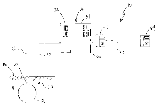
FIG. 1 a simplified schematic of a system for monitoring sound in an
in-ground pipeline in accordance with one preferred embodiment of the
invention.
3
CA 02439954 2003-08-29
WO 02/070947 PCT/US02/06287
FIG. 2 is a simplified block diagram showing the monitoring of sound in an
in-ground pipeline in accordance with one preferred embodiment of the
invention.
FIG. 3 a simplified fragmentary schematic of an in-ground pipeline with
multiple acoustic sensors in accordance with one preferred embodiment of the
invention.
DETAILED DESCRIPTION OF THE INVENTION
The present invention provides an improved method and system for the
monitoring sound in an i11-ground pipeline and the use thereof, such as for
the detection of
contact, e.g., third-party contact, with such an in-ground pipeline. As
detailed below, the
sound monitoring method and system of the invention is particularly helpful
and effective
in minimizing or avoiding the occurrence of false signals such as may result
from at least
certain noncontact events with the pipeline of interest.
The present invention may be embodied in a variety of structures and be
practiced in a variety of manners. As representative, FIG. 1 illustrates the
present invention
as embodied in a system, generally designated by the reference numeral 10, for
the
monitoring of sound in an in-ground pipeline 12 in accordance with one
preferred
embodiment of the invention.
It will be understood that while the invention described hereinafter has
general applicability to the monitoring of sound in various in-ground
pipelines, the invention
is believed to at least initially have particular utility in the detection of
contact, such as by
a third party for example, with a pipeline in the ground. Further, while the
invention is
generally applicable to such monitoring of in-ground pipelines, the invention
is believed to
at least initially have further particular utility for use in conjunction with
those pipelines used
for the transmission of a gaseous medium such as a natural gas stream, for
example.
The pipeline 12 is in-ground, e.g., includes a portion 14 below the ground
surface 16. As identified above, a common concern and persistent problem
relative to
in-ground pipelines is the occurrence of third-party contact with an in-ground
pipeline. Of
particular concern is the occurrence of such third-party contact that may go
unreported and
such as, though not resulting in an immediate pipeline failure, may with time,
result in a
failure such as in the form of a leak or rupture.
The system 10 is generally composed of a first acoustic sensor 20, a second
acoustic sensor 22 and a signal conditioning and processing unit 24. As shown,
the first
acoustic sensor 20 is placed in-ground, e.g., under the ground surface 16, and
is in contact
4
CA 02439954 2003-08-29
WO 02/070947 PCT/US02/06287
with the in-ground pipeline 12. The second acoustic sensor 22 is also placed
in-ground, e.g.,
under the ground surface 16. The second acoustic sensor 22 is desirably spaced
from both
the first in-ground acoustic sensor 20 and the in-ground pipeline 12. In
accordance with a
preferred practice of the invention and as detailed' below, the inclusion and
presence of at
least one such second in-ground acoustic sensor, spaced from both the first in-
ground
acoustic sensor and the in-ground pipeline acoustic sensor can substantially
reduce or
eliminate the occurrence of false signals such as may result from at least
certain noncontact
events with the pipeline of interest.
As will be appreciated by those skilled in the art and guided by the teachings
herein provided, various acoustic sensors such as capable of or useful in the
detecting or
monitoring of various or selected acoustic parameters such as relating to or
resulting from
pipeline vibrations are available and can, if desired, be used in the practice
of the invention.
For example, and without necessarily limiting the broader practice of the
invention, acoustic
sensors such as in the form of accelerometers, microphones or strain gauges
can, if desired,
be used. In view of the existence of substantial experience with the handling
and use of
accelerometers, the use of such devices may be preferred.
The acoustic sensors 20 and 22 are each in signal transmitting communication
with the signal conditioning and processing unit 24 such as via the signal
transmission lines
26 and 30, respectively. Alternatively, one or more of the acoustic sensors 20
and 22 can,
if desired, be in wireless signal transmitting communication with the signal
conditioning and
processing unit 24, such as in a manner known to those skilled in the art and
guided by the
teachings herein provided. Thus, it is to be understood that the broader
practice of the
invention is not necessarily limited by the means or fashion of the signal
transmission.
At the signal conditioning and processing unit 24, the signals from each of
the acoustic sensors 20 and 22 are passed to a signal conditioner, represented
by the
reference numeral 32. In or as a result of the signal conditioner 24, the
signals from each of
the acoustic sensors 20 and 22 are converted into an appropriate voltage,
current or other
readable signal and, if further desired, amplified.
At the signal conditioning and processing unit 24, the conditioned signals
from each of the acoustic sensors 20 and 22 can then be appropriately
processed such as via
one or more processing analysis or technique in a processor 34, such as in the
manner
described in greater detail below, to produce or form an appropriate
corresponding warning
CA 02439954 2003-08-29
WO 02/070947 PCT/US02/06287
signal or message. For example, in FIG. 1, the processor 34 produces a warning
signal or
message such as communicated via the line 36 to a phone 40. The phone 40 in
turn is shown
as in wireless communication (as represented by the dashed line 42) with a
remotely located
phone 44 where there is a capability to appropriately respond to the warning
signal/message.
As will be appreciated by those skilled in the art and guided by the teachings
herein
provided, other forms and means of signal communication can, if desired, be
utilized and the
broader practice of the invention is to be understood as not limited to
particular or specific
forms or means of signal communication.
As identified above, the signals from each of the acoustic sensors 20 and 22
can be appropriately processed such as via one or more processing analysis or
technique in
the processor 34 to produce or form an appropriate corresponding signal. For
example and
in accordance with one preferred embodiment of the invention, the signals are
appropriately
processed such as to produce or form a signal that indicates or corresponds to
the pipeline
having been subjected to a contact of sufficient predetermined intensity, as
provided for by
the selected processing analysis or techiuques.
Those skilled iti the art and guided by the teachings herein provided will
appreciate that various processing analysis or techniques, either alone or in
various selected
combinations, can be used in the practice of the invention. For example and
not necessarily
limiting to the broader practice of the invention, such processing analysis or
techniques may
in accordance with one preferred embodiment of the invention involve
processing of the
signals from each of the acoustic sensors 20 and 22 on at least one basis
selected from the
group consisting of time analysis, frequency analysis and a combination
thereof. Further,
such processing analysis or techniques may in accordance with another
preferred
embodiment of the invention involve processiilg of the signals from each of
the acoustic
sensors 20 and 22 on at least two bases selected from the group consisting of
time analysis,
frequency analysis and a combination thereof. In yet another preferred
embodiment of the
invention, such processing analysis or techniques may involve processing of
the signals from
each of the acoustic sensors 20 and 22 based on time analysis, frequency
analysis and a
combination thereof. As will be appreciated, through the use of 2 or more of
such basis of
signal analysis the possibility of false signals can be further significantly
reduced or
eliminated.
6
CA 02439954 2003-08-29
WO 02/070947 PCT/US02/06287
While various forms or types of time or frequency analysis can be used in the
practice of the invention, the invention will be further herein described with
reference to the
utilization of a "root-mean-square" ("RMS") form of such analysis of the time
signal and/or
a portion of the Power Spectral Density ("PSD"), such as based on known
control analysis.
Time domain RMS:
In this form of analysis, the equation representation (1) from below is used
to differentiate between those sound signals that relate to the in-ground
pipeline (such as by
contact) and those sound signals that relate to the surrounding environment,
e.g., ground in
which the pipeline is buried.
~xof~2 (1)
'_' <_ B
n
where,
xon;
a=i
the signals from the sensor on the pipe and from the sensor spaced from the
pipe each contain n points,
xon;, i = 1 to n is the signal from the sensor on the pipe,
xoff;, i = 1 to n is the signal from the sensor off the pipe, and
B is a predetermined threshold value less than 1 (one).
In this form of analysis, when the inequality representation of equation ( 1 )
holds true, then the subject sound signals relate to the in-ground pipeline
rather than to the
surrounding environment, e.g., ground in which the pipeline is buried. Thus,
in accordance
with a preferred embodiment of the invention, such sound signals correlate or
correspond
to contact with the in-ground pipeline.
Frequency domain RMS:
In this form of analysis, the sound signals from the sensor on the pipe and
from the sensor spaced from the pipe are transformed using the Fast Fourier
Transform
(FFT) in the following manner:
n _J2~ck
Xonk = axon; ~ a ° (2)
(3)
Xoffk = ~xoff; ~ a '2~n
7
CA 02439954 2003-08-29
WO 02/070947 PCT/US02/06287
where,
k=lion,
both Xonk and Xoffk are complex numbers, and
each k of the transform is associated with a frequency.
The PSD of the signals is defined by:
XPon k = Xon k ~ Xon ~k (4)
XPoff k = Xoff,. ~ Xoff k (5)
where,
Xon k is the complex conjugate of Xonk and
Xoffk is the complex conjugate of Xoff~;.
Only certain frequencies of interest are used from the PSD, herein referred to
as the range
1= oc to (3, then the signal is determined to be a contact if the following is
true:
a
~XPoffi2 (6)
T
a
~XPoni2
i=a
where h is a predetermined value less than 1 (one).
Time-frequency (Wavelet) analysis:
In this form of analysis, the data obtained from the sensors using different
time and frequency scales is used such as to produce or result in a 2x2 matrix
of the
amplitudes of the data.
An event like an impact to the pipeline can have a signature that has a unique
pattern of values when viewed in this manner. The algorithm looks for this
unique signature
by comparing the values in the time-frequency values formed by the matrix with
standard
8
CA 02439954 2003-08-29
WO 02/070947 PCT/US02/06287
or established values such as found in a corresponding table. If the pattern
of time-frequency
values are similar, then the signal is designated as an impact.
Voting Scheme
If desired, in those methods in accordance with the invention wherein signals
are processed on at least two bases selected from the group consisting of time
analysis,
frequency analysis and a combination thereof (e.g., time-frequency (wavelet)
analysis), a
weighted voting scheme can be applied thereto. For example, once analysis has
determined
using the above methods that a signal is in the pipeline or is not, it is
given a value of 1 for
a yes and 0 for no. Each of the analysis techniques is also given a weight
determined by the
overall confidence in the methods to be able to detect the signal of interest.
The sum of the
weights~must add to one. Then the following equation can be used to determine
if the signal
is one that is in the pipeline:
3 (7)
~W;.Z~ > K
where,
K is a predetermined threshold,
W; is the weightiilg for each scheme,
Z; is the result of each of the analysis such that each Z; has a value of
either 0 or l,
and
I=lto3
and where,
if the relationship (7) holds true, then the signal is in the pipeline and
if the relationship (7) does not hold true, then the signal is not in the
pipeline.
Turning now to FIG. 2, there is illustrated a simplified bloclf diagram
processing schematic, generally designated 110, showing the monitoring of
sound in an
in-ground pipeline in accordance with one preferred embodiment of the
invention. In
accordance with the processing schematic 110, a signal 112 in the in-ground
pipe is passed
or received, represented by the line 114, to or by a first in-ground acoustic
sensor 116 which
9
CA 02439954 2003-08-29
WO 02/070947 PCT/US02/06287
is in contact with the pipe. Similarly, a signal 120 in the ground adjacent
the pipe of interest
is passed or received, represented by the line 122, to or by a second >lz-
ground acoustic
sensor 124 which, in accordance with a preferred embodiment of the invention
is spaced
from both the first in-ground acoustic sensor and the iil-ground pipeline.
A signal from each of the sensor s 116 and 124, represented by the lines 126
and 125, respectively, can then, if desired and as shown, be forwarded or
advanced to
appropriate signal conditioners, as identified above, and here designated by
the reference
numeral 130 and 132, respectively. The signal conditioners 130 and 132 each
then forward
an appropriately conditioned signal 134 and 136, respectively to signal
analysis 140, such
as described above and such as in a processor.
If the warning conditions of the signal processing analysis are satisfied,
then
a warning is issued or other appropriate signal sent, as represented by the
line 142, such at
to the control box 144.
While the invention has been described above making specific reference to
a system and method having one first in-ground acoustic sensor in contact with
the in-ground
pipeline and one associated second in-ground acoustic sensor spaced from both
the first
in-ground acoustic sensor and the in-ground pipeline, the broader practice of
the invention
is not necessarily so limited. For example, turning to FIG. 3 there is
illustrated a system
fragmentary portion, designated by the reference numeral 210, of an in-ground
pipeline 212.
The fragmentary portion 210 includes two first in-ground acoustic sensors 214
and 216, each
in contact with the in-ground pipeline 212. Two second in-ground acoustic
sensors 220 and
222, respectively, are associated with the first in-ground acoustic sensor 214
and are each
spaced from both the first in-ground acoustic sensor 214 and the in-ground
pipeline 212.
Similarly, two second in-ground acoustic sensors 224 and 226, respectively,
are associated
CA 02439954 2003-08-29
WO 02/070947 PCT/US02/06287
with the first in-ground acoustic sensor 216 and are each spaced from both the
first in-ground
acoustic sensor 216 and the in-ground pipeline 212.
Those skilled in the art and guided by the teachings herein provided will
appreciate that through the inclusion of multiple first in-ground acoustic
sensors in contact
with the in-ground pipeline having at least one associated second in-ground
acoustic sensor
spaced from both the respective first in-ground acoustic sensor and the in-
ground pipeline,
the effective monitoring of extended lengths of pipeline, such as in a
continuous fashion, can
be facilitated. In addition, while the inclusion of multiple associated second
in-ground
acoustic sensors for a first sensor in contact with the pipeline can be
helpful in reducing the
likelihood of a false signal, it will be appreciated that associated factors
such as relating to
cost and increased control complexity may in practice favor the use or
employment of a
siilgle assoicated second sensor, spaced from both the first in-ground
acoustic sensor and the
in-ground pipeline, for a respective first in-ground acoustic sensor in
contact with the
in-ground pipeline.
While the invention has been described above as having particular utility in
conjunction with the monitoring of in-ground pipelines such convey or transmit
a gaseous
medium such as a natural gas stream, it will be understood by those skilled in
the art and
guided by the teachings herein provided that the broader practice of the
invention is not
necessarily so limited. For example, if desired, the iizvention can be
practiced in conjunction
with a pipeline which conveys or transmits a material such as having a
different selected
fluid form such as a liquid, for example.
Further, while the invention has been described above making specific
reference to the detection of contact, e.g., such as by a third party, with an
in-ground
pipeline, it will be understood that the broader practice of the invention is
not necessarily so
11
CA 02439954 2003-08-29
WO 02/070947 PCT/US02/06287
limited. In particular, and without unnecessarily limiting the practice of the
invention, either
or both the method and system of the invention can be applied to the detection
of other kinds
or types of sounds such as may be transmitted through an itl-ground pipeline
and such as
may be desired or found useful in the monitoring of such in-ground pipelines.
For example,
the sound monitoriilg and detection method and system of the invention can, if
desired, be
applied to monitoring or detecting the state (e.g., open or closed condition)
of a valve or
other flow control element within the pipeline.
Thus, the invention provides a method and system for the monitoring of
sound in an in-ground pipeline in a more effective manner than otherwise
previously known
or disclosed. In particular, the invention provides a method and system for
the monitoring
of an in-ground pipeline such as to permit the detection of contact with the
pipeline and
proactively warn of the potential for the occurrence of damage associated with
such contact,
which method and system can operate in a manner which is both more unintrusive
and
effective than previously available.
The invention illustratively disclosed herein suitably may be practiced in the
absence of any element, part, step, component, or ingredient which is not
specifically
disclosed herein.
While in the foregoing detailed description this invention has been described
in relation to certain preferred embodiments thereof, and many details have
been set forth
for purposes of illustration, it will be apparent to those skilled in the art
that the invention
is susceptible to additional embodiments and that certain of the details
described herein can
be varied considerably without departing from the basic principles of the
invention.
12