Language selection

Search

Patent 2440082 Summary

Third-party information liability

Some of the information on this Web page has been provided by external sources. The Government of Canada is not responsible for the accuracy, reliability or currency of the information supplied by external sources. Users wishing to rely upon this information should consult directly with the source of the information. Content provided by external sources is not subject to official languages, privacy and accessibility requirements.

Claims and Abstract availability

Any discrepancies in the text and image of the Claims and Abstract are due to differing posting times. Text of the Claims and Abstract are posted:

  • At the time the application is open to public inspection;
  • At the time of issue of the patent (grant).
(12) Patent Application: (11) CA 2440082
(54) English Title: BOOST TO IMPROVE STRAW CHOPPER SPREADING
(54) French Title: PROPULSEUR PERMETTANT D'AMELIORER L'EPANDAGE PAR BROYEUR DE PAILLE
Status: Deemed Abandoned and Beyond the Period of Reinstatement - Pending Response to Notice of Disregarded Communication
Bibliographic Data
(51) International Patent Classification (IPC):
  • A01F 29/01 (2006.01)
  • A01D 41/12 (2006.01)
  • A01F 29/12 (2006.01)
(72) Inventors :
  • MAYERLE, DEAN (Canada)
  • REDEKOP, LEO (Canada)
  • REDEKOP, KEVIN (Canada)
(73) Owners :
  • DEAN MAYERLE
  • LEO REDEKOP
  • KEVIN REDEKOP
(71) Applicants :
  • DEAN MAYERLE (Canada)
  • LEO REDEKOP (Canada)
  • KEVIN REDEKOP (Canada)
(74) Agent: BATTISON WILLIAMS DUPUIS
(74) Associate agent:
(45) Issued:
(22) Filed Date: 2003-09-09
(41) Open to Public Inspection: 2005-03-09
Availability of licence: N/A
Dedicated to the Public: N/A
(25) Language of filing: English

Patent Cooperation Treaty (PCT): No

(30) Application Priority Data: None

Abstracts

English Abstract


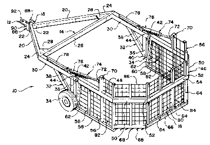
A straw buncher is provided for collecting straw in bunches when
towed across a field and for releasing the straw at desired locations into
large piles.
The straw buncher includes a hitch for connecting to a towing implement and a
frame extending generally upward and rearward therefrom for maximising ground
clearance. The frame is supported on a pair of wheels. A basket is pivotally
mounted on a rear end of the frame. The basket includes a pair of side
collecting
members and a rear collecting member extending therebetween. The collecting
members are in the form of mesh sheets extending generally upright from the
ground. The rear collecting member is spaced upward from the ground and
includes
a plurality of ground engaging tines extending downward from a bottom end for
turning up the straw from the soil such that it may be collected by the
collecting
members. Hydraulics are provided for raising the basket relative to the frame
for
releasing the collected straw.


Claims

Note: Claims are shown in the official language in which they were submitted.

7
CLAIMS
1. A chopper with the means to increase the spread width utilizing a
pneumatic air source directed at the chopper's means for directing the spread.
2. In claim 1 where the air source is mounted remotely from the
chopper
3. In claim 1 where the air source is mounted to the chopper shaft
4 In claims 1-3 where the air sources pressure and/or flow are
remotely controlled
5. In the above claims where the exit air velocity is controlled.
6. In the above claims where the exit air velocity of each section is
independently controlled.
7. in the above claims where the exit air velocity is remotely
controlled.
6. In the above claims where the air source is a fan.
7 In the above claims where the fan utilizes fan blades
8. In the above claims where the fan utilizes an impeller
9. In the above claims where the means for directing the spread is a
chopper's tailboard
10. In the above claims 1 - 8 where the means for directing are
remote fins a substantial distance from the chopper
20. A chopper with the means to increase the spread width utilizing a
pneumatic air source directed at the chopper's inlet.

8
21. In claim 20 where the air source is mounted remotely from the
chopper
22. In claim 20 where the air source is mounted to the chopper shaft
23. In claims 20-22 where the air source's pressure and/or flow are
remotely controlled
24. In the above claims where the exit air velocity is controlled.
25. In the above claims where the exit air velocity of each section is
independently controlled.
26. In the above claims where the exit air velocity is remotely
controlled.
27. In the above claims where the air source is a fan.
28. In the above claims where the fan utilizes fan blades
29. In the above claims where the fan utilizes an impeller

Description

Note: Descriptions are shown in the official language in which they were submitted.


CA 02440082 2003-09-09
AiR BOOST TO IMPROVE STRAW CHOPPER SPREADING
FIELD OF THE INVENTION
The present invention relates generallly to the field of agricultural
machinery.
BACKGROUND OF THE INVENTION
Combine development in recent years have put greater demands on the
straw choppers and chaff spreaders. The main reason s are:
~ Larger combines and larger cutting widths are creating higher flows of straw
and chaff;
~ Wider cutting widths create more demanding spreading widths;
~ Reduced tilling practices have put more demand on even spreading of both
straw and chaff; and
~ Plant breeding has resulted in tougher straw, higher yields and more reside.
Problems with existing technology
~ Air flow created with fan blades mounted within the chopper or a fan mounted
to the chopper drive are restricted to a previously designed airflow
proportional
to the chopper's set rotational speed.
~ Airflow distribution created by either fan blades or a fan impeller mounted
in the
chopper is designed for the average condition and is not adjustable.
~ Air flow entering the chopping region of the chopper assembly is far more
susceptible to plugging than in either the inlet or outlet of the chopper
~ Air flow created with fan blades mounted internally in the chopper is not as
efficient as with an impeller

CA 02440082 2003-09-09
2
Such devices are known in the prior art, i~or example, US 4,526,180, US
4,637,406, US 4,711,253, US 4,735,216, US 5,120,27F~, US 5,232,405, US
5,482,508,
US 5,556,042, US 6,113,491, US 6,416,405, US200210004417A1,
US2002/0142814A1, US2003I0003974A1, the disclosures of which are incorporated
herein by reference.
Clearly, a more efficient method for creating the air pressure and
velocity required for a wide spread chopper is need. This method should
control the
air velocity out of the chopper and therefore the distance of the straw
spread, and
control the air velocity distribution within the chopper and therefore
evenness and
distance of the straw spread. The distribution from the chopper should be
independently and remotely controlled and the system should be flexible enough
so
that the air source can be remotely mounted and remotely controlled.
SUMMARY OF THE INVENTION
It is an objective of the invention to provide an enhanced method to
control the air velocity out of the chopper and therefore the distance of the
straw
spread and the air velocity distribution with-in the chopper and therefore
evenness
and distance of the straw spread.
BRIEF DESCRIPTION OF THE DRAWINGS
FIGURE 1 shows a side view of one embodiment of the invention.
FIGURE 2 shows a top view of the embodiment shown in Figure 1.
FIGURE 3 shows a top view of an embodiment of the invention wherein
the air source is mounted to the chopper shaft.
FIGURE 4 shows a top view of an embodiment of the invention wherein

CA 02440082 2003-09-09
3
the air source cavity is within the chopper assembly.
FIGURE 5 is a side view of an embodiment of the invention including an
internal chopper and secondary air outlets.
FIGURE 6 is a rear view of an embodirnent of the invention shown in
Figure 5.
DESCRIPTION OF THE. PREFERRED EM~ODIIVIENTS
Unless defined otherwise, all technical and scientific terms used herein
have the same meaning as commonly understood by one of ordinary skill in the
art to
which the invention belongs. Although any methods and materials similar or
equivalent to those described herein can be used in the practice or testing of
the
present invention, the preferred methods and materials are now described. All
publications mentioned hereunder are incorporated herein by reference.
Described herein and in the accompanying figures is a chopper with the
means to increase the spread width utilizing a pneumatic air source directed
at the
chopper's means for directing the spread. As discussed below, the air source
may be
mounted remotely from the chopper or mounted to the chopper shaft. The air
source's pressure and/or flow may be remotely controlled.
The exit air velocity may be controlled. In some embodiments, the exit
air velocity of each section may be independently controlled andlor remotely
controlled.
The air source may be a fan, for example, but by no means limited to a
fan that utilizes fan blades or a fan that utilizes an impeller.
The spread directing means may be a chopper's tailboard or remote fins

CA 02440082 2003-09-09
4
distal to the chopper, for example, at a substantial distance from the
chopper.
In another embodiment of the invention, there is provided a chopper with
the means to increase the spread width utilizing a pneumatic air source
directed at the
chopper's inlet.
The air source rnay be mounted remotely from the chopper or mounted
to the chopper shaft.
The air source's pressure andlor flow may be remotely controlled
The exit air velocity may be controlled. The exit air velocity of each section
may be independently controlled andlor remotely controlled.
The air source may be a fan, for example, a fan that utilizes fan blades
or a fan that utilizes an impeller.
In the embodiment shown in Figures '1 and 2, the air source is a
pneumatic fan (10) which is remotely mounted on the combine (11), the speed of
which may be controlled from the cab. An air distribution line (12) serves to
deliver
the pressurized air from the fan (10) to the chopper's am plenum (14). The air
plenum
can be either mounted externally, as shown or can be integrated into the
chopper's
(13) design. The air plenum consists of airflow control (15) and incorporates
air into
the chopper's inlet (16) - as shown or alternately incorporates air into the
discharge
region (17) of the chopper. This reduces plugging - as compared to the air
inlet
mounted between the choppers inlet and outlet as described in US Patent
6,118,491.
The air control may consist of a variable sized air jet entry area across the
width of the
chopper or a number of controllable nozzles (18) directed either at the inlet
or
discharge region of the chopper. it is advantageous to control the air input
with a

CA 02440082 2003-09-09
variable control - each nozzle is adjustable to control the air speed and
therefore
affect the distance of the spread. The nozzle air control may be remotely
mounted to
independently control the spread distance of each fin.
In other embodiments of the invention, the inlet for the chopper's air
5 control is mounted to between the inlet and outlet of the chopper.
In yet another embodiment, shown in Figure 3, a pneumatic fan (20) is
mounted to the chopper shaft (21 ) drawing air from outside of chopper
housing. The
fan is shown as an integral part of the chopper assembly, although in other
embodiments, the fan could be a separate component. The output from the fan
(22)
is directed either at the inlet (23) or outlet (24) of the straw chopper (25)
as described
above. The air serves to accelerate the exiting material providing a much
wider
spread than normal.
In yet another embodiment, the invention includes a pneumatic fan
cavity (31 ) created internally in the chopper assembly (;32) ~ on both sides
of the
chopping area. A fan impeller (33) is mounted to the chopper shaft (34)
drawing air
from the inside of chopper housing (optionally drawing air from the outside of
the
housing). The air serves to accelerate the exiting material providing a much
wider
spread than normal, as shown in Figure 4.
In another embodiment, the invention includes an internal chopper (40)
which utilizes the fan blades on the ends of the chopper. Secondary air
outlets (41 ) -
in this case airflow provided by fan (42) - boosts the spread width, as shown
in
Figures 5 and 6. The air plenum maintains similar control to as described
above.
It is of note that variable air velocities are possible with a fan, fan
blades, or

CA 02440082 2003-09-09
6
impellers fixed to the drive shaft if the chopper drive speed is varied;
however this is
less preferred as there may be dynamic balancing issues due to high rotational
speeds of the chopper.
While the preferred embodiments of the invention have been described
above, it wi(I be recognized and understood that various modifications may be
made
therein, and the appended claims are intended to cover ali such modifications
which
may fall within the spirit and scope of the invention.

Representative Drawing
A single figure which represents the drawing illustrating the invention.
Administrative Status

2024-08-01:As part of the Next Generation Patents (NGP) transition, the Canadian Patents Database (CPD) now contains a more detailed Event History, which replicates the Event Log of our new back-office solution.

Please note that "Inactive:" events refers to events no longer in use in our new back-office solution.

For a clearer understanding of the status of the application/patent presented on this page, the site Disclaimer , as well as the definitions for Patent , Event History , Maintenance Fee  and Payment History  should be consulted.

Event History

Description Date
Application Not Reinstated by Deadline 2008-09-09
Time Limit for Reversal Expired 2008-09-09
Deemed Abandoned - Failure to Respond to Maintenance Fee Notice 2007-09-10
Inactive: IPC from MCD 2006-03-12
Correct Applicant Requirements Determined Compliant 2006-01-23
Application Published (Open to Public Inspection) 2005-03-09
Inactive: Cover page published 2005-03-08
Inactive: Correspondence - Formalities 2004-04-15
Inactive: Adhoc Request Documented 2004-03-24
Inactive: Filing certificate - No RFE (English) 2004-03-17
Inactive: <RFE date> RFE removed 2004-03-17
Inactive: First IPC assigned 2003-10-16
Inactive: IPC assigned 2003-10-16
Inactive: Correspondence - Prosecution 2003-10-09
Inactive: Filing certificate correction 2003-10-09
Application Received - Regular National 2003-10-01
Letter Sent 2003-10-01
Inactive: Filing certificate - RFE (English) 2003-10-01
Amendment Received - Voluntary Amendment 2003-09-09

Abandonment History

Abandonment Date Reason Reinstatement Date
2007-09-10

Maintenance Fee

The last payment was received on 2006-08-08

Note : If the full payment has not been received on or before the date indicated, a further fee may be required which may be one of the following

  • the reinstatement fee;
  • the late payment fee; or
  • additional fee to reverse deemed expiry.

Patent fees are adjusted on the 1st of January every year. The amounts above are the current amounts if received by December 31 of the current year.
Please refer to the CIPO Patent Fees web page to see all current fee amounts.

Fee History

Fee Type Anniversary Year Due Date Paid Date
Application fee - small 2003-09-09
MF (application, 2nd anniv.) - small 02 2005-09-09 2005-09-06
MF (application, 3rd anniv.) - small 03 2006-09-11 2006-08-08
Owners on Record

Note: Records showing the ownership history in alphabetical order.

Current Owners on Record
DEAN MAYERLE
LEO REDEKOP
KEVIN REDEKOP
Past Owners on Record
None
Past Owners that do not appear in the "Owners on Record" listing will appear in other documentation within the application.
Documents

To view selected files, please enter reCAPTCHA code :


To view images, click a link in the Document Description column. To download the documents, select one or more checkboxes in the first column and then click the "Download Selected in PDF format (Zip Archive)" or the "Download Selected as Single PDF" button.

List of published and non-published patent-specific documents on the CPD .

If you have any difficulty accessing content, you can call the Client Service Centre at 1-866-997-1936 or send them an e-mail at CIPO Client Service Centre.


Document
Description 
Date
(yyyy-mm-dd) 
Number of pages   Size of Image (KB) 
Abstract 2003-09-08 1 34
Claims 2003-09-08 2 54
Description 2003-09-08 6 247
Drawings 2003-09-08 3 98
Representative drawing 2003-11-02 1 39
Acknowledgement of Request for Examination 2003-09-30 1 173
Filing Certificate (English) 2003-09-30 1 159
Filing Certificate (English) 2004-03-16 1 158
Reminder of maintenance fee due 2005-05-09 1 110
Courtesy - Abandonment Letter (Maintenance Fee) 2007-11-04 1 173
Correspondence 2003-10-08 2 142
Correspondence 2003-09-08 4 107
Correspondence 2004-04-14 2 57
Correspondence 2007-08-08 2 45