Note: Descriptions are shown in the official language in which they were submitted.
CA 02440124 2003-09-09
1
TITLE OF THE INVENTION:
Pallet assembly
FIELD OF THE INVENTION
The present invention relates to a pallet assembly.
BACKGROUND OF THE INVENTION
As shipping costs increase, it is becoming impractical
to ship a fully assembled pallet across the country.
Instead, pallet assemblies have been developed, which enable
pallets to be disassembled and the pieces shipped in
relatively compact bundles in order to reduce shipping costs.
The pallet assemblies can then be reassembled in preparation
for use, when they arrive at their destination.
SUH~1ARY OF THE INVENTION
The present invention relates to an alternative
configuration of pallet assembly.
According to the present invention there is provided a
pallet assembly which includes a pair of elongate lifting
tine receiving members. Each of the lifting tine receiving
members has an open first end, an open second end, a top
surface and opposed sides. An integrally formed longitudinal
engagement member extends like a spine along the top surface
between the first end and the second end. At least one body
is provided having ~_ bottom surface with a pair of
longitudinal engagement channels. Each of the engagement
channels has a first end, a second end, and is adapted to
interlock with the engagement member of one of the lifting
tine receiving members when the engagement member is inserted
into one of the engagement channels from one of the first end
or the second end.
CA 02440124 2003-09-09
2
BRIEF DESCRIPTION OF THE DRAWINGS
These and other features of the invention will become
more apparent from the following description in which
reference is made to the appended drawings, the drawings are
for the purpose of illustration only and are not intended to
in any way limit the scope of the invention to the particular
embodiment or embodiments shown, whereine
FIGURE 1 is an end view of the first embodiment of an
elongate lifting tine receiving member constructed in
accordance with the teachings of the present invention.
FIGURE 2 is a top perspective view of the first
embodiment of a pallet assembly construcaed in accordance
with the teachings of the present invention.
FIGURE 3 is a bottom perspective view of a plank
~i5 illustrated in FIGURE 2.
FIGURE 4 is an end view of an alternative form of the
elongate lifting tine receiving member illustrated in FIGURE
1.
FIGURE 5 is an end view of an alternative form of the
elongate lifting tine receiving member illustrated in FIGURE
4.
FIGURE 6 is an end view of a second alternative form of
the elongate lifting tine receiving member illustrated in
FIGURE 1.
FIGURE 7 is an end view of the second embodiment of an
elongate lifting tine receiving member constructed in
accordance with the teachings of the present invention.
FIGURE 8 is a top perspective view of the second
embodiment of a pallet assembly constructed in accordance
with the teachings of the present invention.
FIGURE g is an end view of the pallet assembly
illustrated in FIGURE 8.
FIGURE 10 is a bottom perspective view of a first weight
bearing sheet illustrated in FIGURE 9.
CA 02440124 2003-09-09
3
FIGURE 11 is a top perspective view of a second weight
bearing sheet illustrated in FIGURE 9.
FIGURE 12 is an end view of the first embodiment of an
elongate lifting tine receiving member illustrated in FIGURE
1, disassembled fo.r storage.
DETAILED DESCRIPTION OF THE PREFERRED F~lBODIMENT
A first preferred embodiment, a pallet assembly
generally identified by reference numeral 10, will now be
described with reference to FIGURES 1 through 6 and 12 . A
second preferred embodiment, a pallet assembly generally
identified by reference numeral 100, will now be described
with reference to FIGURES 7 through 11.
.- J
Structure and Relationship of Parts of the first
embodiment:
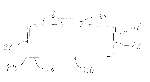
Referring to FIGURE 2, pallet assembly 10 has a pair of
elongate lifting tire receiving members 12, each of tine
receiving members i2 having an open first end 14 and an open
second end 16. Referring to FIGURE 1, tine receiving members
12 are further adapted with a top surface 18, an open bottom
20, opposed sides 22., and an integrally formed longitudinal
dove tail engagement: member 24, which extends like a spine
along top surface 18 between first end 14 and second end 16
as illustrated in FIGURE 2. Referring to FIGURE 1, each of
tine receiving members 12 has an inwardly extending flange 26
which extends inwardly from a remote edge 28 of opposed sides
22. Referring to FIGURE 3. several planks 30 are provided,
having a bottom surface 32 with a pair of dove tail
engagement channels 34, each of engagement channels 34 having
a first end 36 and a second end 38. Referring to FIGURES 2
and 3, each of dove tail engagement channels 34 of planks 30
are adapted to interlock with each of dove tail engagement
CA 02440124 2003-09-09
4
members 24 of tine .receiving members 12 when engagement
member 24 is inserted into one of engagement channels 34 from
one of first end 36 or second end 38. Referring to FIGURES 4
and 5, alternate profiles of tine receiving members 12 are
shown wherein each of opposed sides 22 has at least one
concave channel 40. It will be appreciated that various
numbers of planks 30 and lengths of tine receiving members 12
may be used.
Operation
of the first
embodiment:
The use and operation of pallet assembly 10 will now be
described with reference to FIGURES 1 through
6 and FIGURE
12. Referring illustrated in
to FIGURE
12, where
pallet 10
FIGURE 2, needs to be stored or shipped, each 30
of planks
are slid along each of engagement members 24 until they are
clear of tine receiving members 12. P~s a result, ine
t
receiving members 12 and planks 30 may be bundled or
otherwise packed in an eff~_cient manner. Referring to
FIGURES 1 and 3, where a pallet is to be assembled, tine
receiving members 12 are spaced and engagement members 24 are
interlocked with engagement channels 34 of each of planks 30
by inserting first end 14 or second end 16 of engagement
member 24 into second end 38 or first end 36 of engagement
channel 34 such that planks 10 are aligned into an integrated
pallet as shown in FIGURE 2. Referring to FIGURES 4, 5, and 6
where extra strength or durability may be required,
reinforced tine receiving members with channels 40 may be
used. Due to the 'modular' construct'~on of the first
embodiment pallet 10, it may be more suited to situations
where flexibility and adaptation are required. Referring to
FIGURE 6. where extra strength or durak>ility may be required,
channels 40 such as those having a square shape as
illustrated in FIGURE 6 are preferred. It will also be
appreciated that while As a result, tine receiving members 12
CA 02440124 2003-09-09
are shown as having engagement members 24 as illustrated in
FIGURE 4, more than one engagement members 24 could be
provided as illustrated in FIGURE 5.
5 Structure and Relationship of Parts of the second
embodiment:
Referring to FIGURE 8, pallet assembly 100 has a pair of
elongate lifting tine receiving members 102, each of tine
receiving members 102 having an open first end 104 and an
~~0 open second end 106., Referring to FIGURE 7, tine receiving
members 102 are further adapted with a top surface 108, a
closed bottom 110, opposed sides 112, and an integrally
formed longitudinal dove tail engagement member 114~ which
extends like a spine along top surface 108 between first end
104 and second end 106 and an integrally formed longitudinal
dove t ail engagement member 115 which extends like a spine
along the closed bottom 110 between first end 104 and second
end 106 as illustrated in FIGURE 8. Referring to FIGURE 9, a
first weight bearing sheet 116 has a bottom surface 118 with
a pair of dove tail engagement channels 120. Referring to
FIGURE 10, each of engagement channels 120 :has a first end
122 and a second end 124 and is adapted to interlock with
engagement member 114 of one of tine receiving members 102
when engagement member 114 is inserted into one of engagement
channels 120 from one of first end 122 or second end 124 as
illustrated in FIGURE 8. Referring to FIGUEtE 9, a second
weight bearing sheet 126 has a top surface 128 with a pair of
dove tail engagement channels 130. Referring to FIGURE 11,
each of engagement channels 130 has a first end 132, a second
end 134, and are adapted to interlock with engagement member
115 or~ closed bottom 110 of one of lifting tine receiving
members 102 when engagement member 115 is inserted into one
of engagement channels 130 from one of first end 132 or
second end 134 as illustrated in FIGURES 8 and 9. It will be
CA 02440124 2003-09-09
appreciated that various dimensions of first weight bearing
sheet 116 and second weight bearing sheet 126 and lengths of
tine receiving members 102 may be used.
Operation of the second embodiment:
The use and operation of pallet assembly 100 will now be
described with reference to FIGURES ? through 11. Referring
to FIGURE 8, where pallet 100 needs to be stored or shipped,
each of first weight bearing sheet 116 and second weight
bearing sheet 126 are slid along each of engagement members
114 and 115 respectively until they a.re clear of tine
receiving members 102. As a result, tine receiving members
102 and first weight bearing sheet 116 and second weight
bearing sheet 126 may be bundled or otherwise stacked in an
efficient manner. Referring to FIGURES ?, 10 and 11, where a
pallet is to be assembled, tine receiving members 12 are
spaced and engagement members 115 are interlocked with
engagement channels 130 of second weight bearing sheet 126 by
inserting first end 104 or second end 106 of engagement
member 115 into second end 134 or first end 132 of engagement
channels 130. Engagement members 114 are then interlocked
with engagement channels 120 of first weight bearing sheet
il6 by inserting first end 104 or second end 106 of
engagement member 114 into second end i24 or first end 122 of
engagement channel 120 such that first weight bearing sheet
116 and second weight bearing sheet 126 are aligned into an
integrated pallet as shown in FIGt3RE 8. Due to the
'sandwich' construction of the second embodiment pallet 100,
it may be more suited to situations where rigidity and
strength are required.
In this patent document, the word
°°comprising°° is used
in its non-limiting sense to mean that items following the
word are included, but items not specifically mentioned are
CA 02440124 2003-09-09
7
not excluded. A reference to an element by the indefinite
article "a" does not exclude the possibility that more than
one of the element is present, unless the context clearly
requires that there be one and only one of the elements.
It will be apparent to one skilled in the art that
modifications may be made to the illustrated embodiment
without departing from the spirit and scope of the invention
as hereinafter defined in the Claims.