Note: Descriptions are shown in the official language in which they were submitted.
CA 02440130 2003-08-29
WO 02/077314 PCT/US02/05120
-1-
CORROSION RESISTANT COMPONENT AND METHOD FOR
FABRICATING SAME
CROSS-REFERENCE TO RELATED APPLICATIONS
Not Applicable.
BACKGROUND OF THE INVENTION
The present invention relates generally to materials processing and, in
particular, to the fabrication of corrosion and erosion resistant components
for use in
industrial applications.
Historically, steel alloys have been utilized in countless industrial
applications.
And despite the recent widespread development and commercialization of so-
called
"high-performance" materials (e.g., alloys, ceramics, and composites), steel
alloys are
still actively used in many such applications. This is likely attributable to
their
relatively unique combination of high strength and low cost.
The use of steel alloys in some types of industrial applications, however, is
contraindicated. Among such applications are certain offshore oil refineries
in which
pipes and tubes are used to carry and transport oil. The reactivity of
components of
the oil (e.g., hydrogen sulfide) causes corrosion of the inner surfaces of the
steel
pipes/tubes in an unacceptably short amount of time, which can be even further
shortened by turbulent flow of the oil and due to abrasion.and/or erosion
caused by
particles suspended in the oil.
One solution to the shortcomings encountered when using steel a.Iloys in fluid
transport applications is to instead use components containing high
concentrations of
nickel, chromium or cobalt in such applications. The problem is that although
such
components exhibit increased corrosion and erosion resistance, the expense of
fabricating such alloys renders their use on such a scale cost prohibitive. '
Some in the art have experimented with a compromise, namely lining portions
of steel pipes and tubes with corrosion resistant materials in order to gain
corrosion
resistance. It has proven difficult, however, to do so inexpensively while
ensuring that
CA 02440130 2003-08-29
WO 02/077314 PCT/US02/05120
-2-
the resulting product not only exhibits increased corrosion resistance, but
also is
durable and accurately shaped.
Therefore, a need exists for a technique to fabricate a corrosion resistant
component from a strong and inexpensive, yet corrosion-susceptible material
such as
steel by cladding the steel with one or more comparatively expensive,
corrosion and/or
erosion resistant materials in order to cost effectively increase the
corrosion and/or
erosion resistance of the steel without hampering its innate strength, and
while being
able to control the shape of the resulting component.
SUMMARY OF THE INVENTION
The present invention provides corrosion and erosion resistant components and
a method of fabricating such components by metallurgically bonding at least
two
different materials together. Although the invention is primarily shown and
described
in conjunction with fabricating industrial components such as valves, pipes
and tubes,
it is understood that linear and non-linear shaped components of nearly any
size,
specific shape, and function may be fabricated on any scale in accordance with
the
present invention.
In an exemplary aspect of the present invention, a first corrosion or erosion
resistant material is applied onto a core or substrate via an appropriate
metallic spray
technique. The core and layer of first material are then at least partially
enclosed by a
surrounding capsule such that an empty space is defined within the capsule.
This
space is substantially filled with a second material (e.g., a metallic
powder), after
which the capsule is sealed and then processed to cause the second material to
densify
and to metallurgically bond to the first material.
Thereafter, the core material and capsule are removed chemically and/or
mechanically to leave a fabricated component. The component will have a shape
and
size approximating that of the space that had been defined between the capsule
and the
layer of first material.
In one aspect of the present invention, the compositions of the first and
second
materials are adjusted (e.g., by modifying the feed of the metal powder to the
spray
deposition device) to provide a compositional gradient, which, in turn, serves
to
CA 02440130 2005-07-18
-3-
diffuse the stresses that may be generated by differences in the thermal
expansion
of the first and second materials. Because these stresses are diffused, a
component
fabricated in accordance with the present invention not only is accurately
shaped
and corrosion resistant, but also is less susceptible to cracking and,
therefore, is
highly durable.
In another aspect, the present invention provides a method of fabricating a
component, comprising the steps of: providing a sacrificial core having an
outer
surface of a predetermined shape; applying a first material onto at least a
portion of
the outer surface of the sacrificial core by a spraying technique selected
from the
group consisting of spray deposition, plasma spraying, and high velocity oxy-
fuel
spraying; substantially enclosing the first material and the sacrificial core
within a
capsule; introducing a quantity of a second material, in powder form, within
the
capsule such that at least some of the first material is in contact with at
least some of
the second material; and causing the first material to metallurgically bond to
the
second material using hot isostatic pressing technique.
In another aspect, the present invention provides a method of fabricating a
component, comprising the steps of: providing a core having a predetermined
shape; spray-depositing a first material onto at least a portion of the core;
substantially enclosing the first material within a capsule; introducing a
quantity of a
second material in powder form within the capsule, wherein the second material
is
less corrosion resistant and/or wear resistant than the first material; hot
isostatically
pressing the first material for a time in the range of about two hours to
about six
hours at a temperature in the range of about 1500 F to 2500 F and at a
pressure in
the range of about 5000 psi to 45000 psi, such that the first material
metallurgically
bonds to the second material; and removing the core and the capsule to yield a
fabricated component having a hollow cavity with an inner surface formed of
the
first material.
In another aspect, the present invention provides a method of fabricating a
component, comprising the steps of: providing a core having a predetermined
shape;
spray-depositing a first material onto at least a portion of the core;
substantially
enclosing the first material within a capsule; introducing a quantity of a
second
material in powder form within the capsule, wherein the second material is
less
corrosion resistant and/or wear resistant than the first material; hot
isostatically
CA 02440130 2007-03-21
-3a-
pressing the first material at a pressure in the range of about 5000 psi to
45000 psi, such
that the first material metallurgically bonds to the second material; and
removing the core
and the capsule to yield a fabricated component having a hollow cavity with an
inner
surface formed of the first material.
In another aspect, the present invention provides a method of fabricating a
component, comprising the steps of: providing a sacrificial core having an
outer surface of
a predetermined shape; spray-depositing a first material onto at least a
portion of the core;
substantially enclosing the first material within a capsule; introducing a
quantity of a
second material in powder form within the capsule, wherein the second material
is less
corrosion resistant and/or wear resistant than the first material; and hot
isostatically
pressing the first material for a time in the range of about two hours to
about six hours at a
temperature in the range of about 1500 F to 2500 and at a pressure in the
range of about
5000 psi to 45000 psi, such that the first material metallurgically bonds to
the second
material.
In another aspect, the present invention provides a method of fabricating a
corrosion
and erosion resistant component, comprising the steps of: providing a
sacrificial core
having an outer surface of a predetermined shape; applying a first material
onto at least a
portion of the outer surface of the sacrificial core; substantially enclosing
the first material
within a capsule; introducing a quantity of a second material, in powder form,
within the
capsule such that at least some of the first material is in contact with at
least some of the
second material; and causing the first material to metallurgically bond to the
second
material, wherein the fabricated component has a non-linear shape.
BRIEF DESCRIPTION OF THE DRAWINGS
The invention will be more fully understood from the following detailed
description taken in conjunction with the accompanying drawings, in which:
FIG. I is a flow diagram illustrating steps for fabricating a corrosion
resistant
component in accordance with the present invention;
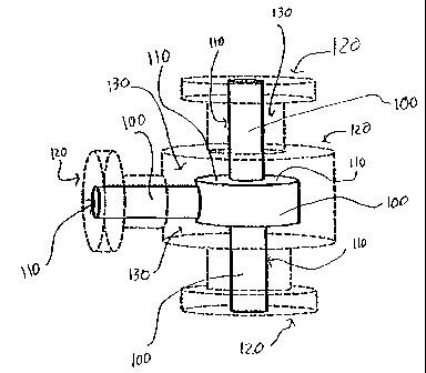
FIG. 2 is a schematic isometric view of a core and a capsule used in the
fabrication of a con=osion resistant component in accordance with the process
of FIG. 1;
CA 02440130 2007-03-21
-3b-
FIG. 3 is top view of an alternate embodiment of a core and capsule in
accordance with the present invention; and
FIG. 4 is a cross-sectional top view of a corrosion resistant component
fabricated
in accordance with the present invention.
DETAILED DESCRIPTION OF THE INVENTION
FIG. 1 depicts a flow diagram 10 illustrating the steps of a process for
fabricating
a corrosion and erosion (i.e., wear) resistant component in accordance with
the present
invention.
This process allows for the convenient, inexpensive fabrication of durable,
coirosion resistant components of various tailored sizes and shapes. The
fabricated
components are comprised of a minimum of two materials, at least one of which
is
CA 02440130 2003-08-29
WO 02/077314 PCT/US02/05120
-4-
strong yet inexpensive, and at least another of which is comparatively more
expensive,
but exhibits increased corrosion and/or erosion resistance vis-a-vis the other
material.
The fabrication process entails applying one or more corrosion resistant first
materials onto a sacrificial core or substrate and then enclosing this first
material and
the core to form surrounding capsule. Any space defined within the capsule is
then
substantially filled with a second material. The capsule is then sealed and
processed to
cause the second material to densify and to metallurgically bond to the first
material at
contact areas between the first and second materials. Thereafter, the core and
capsule
are removed via chemical and/or mechanical processes to yield a component with
a
linear or non-linear shape that approximates that of the space that existed
within the
capsule.
At step 20 of the fabrication process of FIG. 1, a sacrificial core or
substrate is
provided. Exemplary cores 100, 200 are shown in FIGS. 2 and 3, the core 100
being
useful in fabricating a valve component, and the core 200 being useful in
fabricating a
pipe or tube component. Once the core 100, 200 is prepared, the process
continues to
step 30, which entails applying one or more substantially corrosion and/or
erosion
resistant first materials onto some or substantially all of the outer surface
110, 210 of
the core.
Application of the first material(s) may be accomplished via a number of
techniques known in the art, including, but not limited to, spraying
techniques,
welding techniques, and chemical processes. Exemplary spraying techniques
include
both "spray to solid" and "spray to powder" techniques. Specific suitable
spraying
techniques include, but are not limited to, spray deposition (e. g. , the
Osprey process),
plasma spraying, high velocity oxy-fuel (HVOF) spraying and wire thermal
spraying.
Exemplary welding techniques include, but are not limited to, weld overlaying,
plasma transfer arc welding, laser welding and gas metal arc welding, while
exemplary
chemical processes include, but are not limited to, electrolysis, chemical
precipitation,
adhesive bonding, chemical vapor deposition (CVD) and physical vapor
deposition
(PVD).
CA 02440130 2003-08-29
WO 02/077314 PCT/US02/05120
-5-
In an exemplary embodiment of the present invention, the first material is
spray
deposited onto the core in powder form in order to create a porous layer of
first
material, which, in turn, allows for penetration of subsequently added second
material.
The thickness of the layer of the first material(s) will vary depending on a
number of factors, such as the number of materials that form the layer, the
operating
environment (e.g., temperature, pressure, corrosivity and abrasiveness) to
which the
finished component is subjected, the desired amount/degree of corrosion
resistance of
the component, the size and shape of the component, etc. The selection of the
appropriate thickness of the first material is routine to one of ordinary
skill in the art.
Generally, when fabricating an industrial part such as the valve body shown in
FIG. 2, or the pipe/tube shown in FIG. 3, the first material(s) should be
applied to the
outer surface 110, 210 of the core 100,200 to form a layer with a total
thickness in the
range of about 0.05 inch to 0.5 inch (1.27 millimeter to 12.7 millimeters),
with a
thickness in the range of about 0.1 inch to 0.3 inch (2.54 millimeters to 7.26
millimeters) being preferred.
This first material layer may be comprised of one or more corrosion resistant
materials, such as metal-based alloys, cermets and/or ceramics. Exemplary
metal-
based materials include, but are not limited to, stainless steels, nickel-
based alloys
such as Inconel 600, Inconel 625 and Inconel 800, cobalt-based alloys such as
Stellite
1, Stellite 6, Tribaloy T400, and iron-based alloys such as A-286 and Incoloy
800.
Exemplary cermet materials include, but are not limited to, Stelcar 1, JK-112
and
JK9153, while an exemplary ceramic material is partially stabilized zirconia
(PSZ).
These exemplary nickel-based alloys, cobalt-based alloys and cermet materials
are available as spray deposits from commercial suppliers such as such as
Deloro
Stellite Co. , Inc. of Goshen, Indiana, while PSZ is available from commercial
suppliers such as ICI Advanced Ceramics of Auburn, California.
Once the layer of first material(s) is applied to the sacrificial core 100,
200, the
process continues to step 40 during which the first material(s) and the core
are encased
or otherwise entirely or partially enclosed by a surrounding capsule.
Exemplary
capsules 120 (for a valve component 100) and 220 (for a pipe/tube component
200) are
shown, respectively, in FIGS. 2 and 3.
CA 02440130 2003-08-29
WO 02/077314 PCT/US02/05120
-6-
Once the core is encased, a void or space 130, 230 is created/defined between
the capsule and the layer of first material on the outer surface 110, 210 of
the core
100, 200. Thus, the size and shape of this space 130, 230 is dependant on the
size and
shape of the core 100, 200 and the capsule 120,220, as well as the thickness
of the
first material that was spray-deposited on the outer surface 110, 210 of the
core.
At step 50 of the fabrication process of FIG. 1, this space 130, 230 is at
least
partially filled with a second material such that the second material
substantially
surrounds or covers the layer of the first material on the core 100, 200. In
an
exemplary embodiment of the present invention, the space 130, 230 is
substantially
filled with a powder-based second material such that the second material is
capable of
penetrating the porous layer of first material.
The second material should be a relatively inexpensive, yet should possess the
mechanical properties (e.g., strength, stiffuess, durability) necessary to
meet
requirements of the ultimate usage conditions of the finished component.
Moreover, it
is understood that the second material may actually be comprised of more than
one
material.
Exemplary second materials for use in fabricating industrial components
include, but are not limited to, duplex stainless steel alloys, 9Cr - 1Mo
steel, 4140
steel and 4340 steel. Each of these alloys is sold in powder form by
commercial
suppliers such as Deloro Stellite Co. , Inc. of Goshen, Indiana and ANVAL,
Inc. of
Torshala Sweden:
Once the appropriate amount of second material is added, the capsule 120, 220
is hermetically sealed and outgased through an evacuation tube (not shown) at
a
temperature in the range of about 200 F to 2000 F, preferably in the range of
about
400 F to 600 F. The outgasing process is performed until a predetermined
vacuum
level within the capsule is reached, wherein that vacuum level signifies that
most, if
not all, of the moisture that were contained within the powdered second
material have
been elinlinated. Typically, this predetermined vacuum level is in the range
of about
50 microns to 200 microns, with about 100 microns being the approximate vacuum
level being preferred. In order to obtain a vacuum level of approximately 100
microns,
CA 02440130 2003-08-29
WO 02/077314 PCT/US02/05120
-7-
the entire outgasing process usually lasts in the range of about 4 to 48
hours, the exact
duration depending on such factors as the weight and moisture content of the
powder.
Once the outgasing process is completed, the evacuation tube is sealed via a
method known in the art, such as hydraulic crimping and/or welding, in order
to
provide a hermetic seal around the capsule and, thus, around the first
material and
core.
At step 60 of the FIG. 1 process, the sealed capsule 120, 220 is treated in
order
to cause the first material to densify (i.e., to remove residual pores and
voids within
the first material) and to metallurgically or diffusively bond it to the
second material.
This treatment can occur via a number of techniques known in the art
including, but
not limited to, press and sinter, Ceracon, Fluid Die, and Rapid
Omnidirectional
Compaction (ROC) but, preferably, occurs by hot isostatically pressing (HIP)
the
capsule 120, 220 for a predetermined time at a predetermined temperature and a
selected pressure.
In an exemplary embodiment of the present invention, the temperature during
HIP treatment of the capsule is in the range of about 1500 F to 2500 F,
preferably in
the range of about 1800 F to 2200 , and most preferably in the range of about
2000 F
to 2100 F, while the HIP pressure is in the range of about 5000 psi to 45000
psi,
preferably in the range of about 13000 psi to 16000 psi, and most preferably
in the
range of 14500 psi to 15500 psi. The time during which the capsule is HIPed is
in the
range of about two hours to six hours, preferably in the range of about three
to five
hours, and most preferably approximately four hours.
Following treatment of the capsule, the first and second materials are
strongly
metallurgically bonded together. In an embodiment in which a compositional
gradient
is created between the first and second materials during the HIP treatment.
This
gradient, in turn, serves to diffuse the stresses generated by differences in
thermal
expansion that may exist between the first material and second material.
Because these
stresses are diffused, a component fabricated as such not only is accurately
shaped and
corrosion resistant, but also is less susceptible to cracking and, therefore,
is highly
durable.
CA 02440130 2003-08-29
WO 02/077314 PCT/US02/05120
-8-
Following the HIP treatment, the process continues to step 70, during which
the shaped core and capsule are removed/eliminated. A number of chemical and
mechanical techniques exist in the art to elinlinate the core and capsule,
including, but
not limited to, chemical or acid pickling, and/or machining.
In order for the core and capsule to be easily removable via, for example,
pickling or machining techniques, while still ensuring that the shape and/or
mechanical
properties of the component are not compromised during the core and capsule
removal
process, the core and capsule are preferably made of a material that is more
susceptible to pickling or machining than the first and second materials that
comprise
the component.
Many such materials exist, including, but not limited to, sheet metals such as
a
carbon steel sheet metal. Exemplary carbon steel sheet metals include, but are
not
limited to, AISI 1010, AISI 1018 and AISI 1020. One of ordinary skill in the
art will
readily appreciate that although the core 100, 200 and capsule 120, 220 are
generally
constructed of the same material, they may be formed from different materials
as well.
Once the core and capsule have been elinlinated, the component is considered
completely or substantially fabricated. Exemplary components include, but are
not
limited to, tubes, pipes, and valves. The finished component can be linear or
non-
linear in shape, wherein exemplary non-linear shapes for the components
include, but
are not limited to, a"T-shape," a cross shape, and any other shape that
includes a
bend, junction or intersection.
A fabricated pipe/tube component 300 made using the core and capsule of
FIG. 3 is shown in FIG. 4. The component 300 includes a layer 310 of the first
material and a layer 320 of the second material that are metallurgically
bonded at their
junction 330. The component 300 further includes a hollow cavity 340 where the
core, prior to being removed, was located. The inner surface 350 of the layer
310 of
first material has a shape that resembles the approximate shape of the outer
surface of
the core, while the outer surface 360 of the layer 320 of the second material
has a
shape that resembles the approximate shape of the inner surface of the
capsule.
CA 02440130 2007-03-21
-9-
Fabrication of a component in accordance with the process of FIG. 1 generally
yields a "near net shape" component - that is, a component that requires
little to no
significant post-fabrication surface treatment. It is understood, however,
that the external
surface 350 of the finished component may require some surface treatment by
one or more
surface treatment methods (e.g., cleaning, machining, grit blasting and/or
polishing) known
in the art.
One skilled in the art will appreciate further features and advantages of the
invention based on the above-described embodiments. Accordingly, the invention
is not to
be limited by what has been particularly shown and described, except as
indicated by the
appended claims.