Language selection

Search

Patent 2440490 Summary

Third-party information liability

Some of the information on this Web page has been provided by external sources. The Government of Canada is not responsible for the accuracy, reliability or currency of the information supplied by external sources. Users wishing to rely upon this information should consult directly with the source of the information. Content provided by external sources is not subject to official languages, privacy and accessibility requirements.

Claims and Abstract availability

Any discrepancies in the text and image of the Claims and Abstract are due to differing posting times. Text of the Claims and Abstract are posted:

  • At the time the application is open to public inspection;
  • At the time of issue of the patent (grant).
(12) Patent Application: (11) CA 2440490
(54) English Title: ARMREST
(54) French Title: ACCOUDOIR
Status: Deemed Abandoned and Beyond the Period of Reinstatement - Pending Response to Notice of Disregarded Communication
Bibliographic Data
(51) International Patent Classification (IPC):
  • A47C 7/54 (2006.01)
  • A47C 1/03 (2006.01)
(72) Inventors :
  • MAIER, KLAUS (Germany)
  • KLASENER, MICHAEL (Germany)
  • STENZEL, THOMAS (Germany)
(73) Owners :
  • SEDUS STOLL AG
(71) Applicants :
  • SEDUS STOLL AG (Germany)
(74) Agent: NORTON ROSE FULBRIGHT CANADA LLP/S.E.N.C.R.L., S.R.L.
(74) Associate agent:
(45) Issued:
(22) Filed Date: 2003-09-08
(41) Open to Public Inspection: 2004-04-04
Examination requested: 2008-09-03
Availability of licence: N/A
Dedicated to the Public: N/A
(25) Language of filing: English

Patent Cooperation Treaty (PCT): No

(30) Application Priority Data:
Application No. Country/Territory Date
02 022 433.3 (European Patent Office (EPO)) 2002-10-04

Abstracts

English Abstract


In the case of a chair, in particular a swivel chair
for the office, the armrest is made up of an armrest
carrier, which comprises a carrier (1) and a sleeve (2)
sliding thereon and is attached to the seat at the
bottom by a seat flange (3) which can be displaced
transversely to the seat direction, and of an arm
support (10, 11), which can. be displaced longitudinally
via a guide (7) and can be rotated via a rotary part
(4) mounted in a rotary bearing (5). The guide (7) is
arranged parallel, but eccentrically in relation, to
the axis of symmetry of the arm support. Since the
rotatability of the arm support is at least 180°, it is
possible to set different clear distances between the
two arm supports (10, 11) of the chair.


Claims

Note: Claims are shown in the official language in which they were submitted.

-8-
Claims
1. Three-dimensionally adjustable armrest, in the
case of which the armrest carrier (1) can be adjusted
in respect of height and the arm support (10, 11) can
be adjusted longitudinally in a horizontal plane, and
the arm support (10, 21) can also be rotated through at
least 90° about an axis (17), characterized in that the
axis (17) is eccentric in relation to the axis of
symmetry of the arm support (10, 11) which runs in the
seat direction, and the longitudinal adjustability and
the eccentric rotatability of the arm support (10, 11)
are achieved in that a carrying panel (10) of the arm
support is connected to a longitudinally running guide
(7) in which the guide noses (6) of a rotary part (4)
run, the rotary part being mounted in a rotatable
manner in the rotary bearing (5) at the top end of the
armrest carrier (1, 2), and the guide (7) being
arranged parallel, but eccentrically in relation, to
the axis of symmetry of the arm support (10, 11).
2. Armrest according to Claim 1, characterized in
that the vertical distance between the eccentric point
of rotation and the axis of symmetry of the arm support
is between 5 and 15 mm, preferably 10 mm.
3. Armrest according to Claim 1, characterized in
that the guide (7) is arranged in a housing (12) which
is screwed to the underside of the carrying panel (10)
by means of the screws (13), and connection to the
rotary part (4) is achieved in that a retaining plate
(8) is provided above the guide (7), the retaining
plate being screwed to the guide noses (6) of the
rotary part (4) via the retaining screws (9).
4. Armrest according to Claim 1, characterized in
that the armrest carrier comprises a carrier (1), which
is connected to the seat via a seat flange (3) which
can be adjusted transversely to the seat direction, and

-9-
a sleeve (2), which slides on the carrier (1) and in
the top end of which is provided the rotary bearing (5)
with the rotary part (4), and in that vertical rotary
latching protrusions (15) are provided on the
circumference of the rotary part (4) and horizontal
expansible latching protrusions (14) are provided
between the underside of the guide housing (12) and the
rotary part (4), with the result that the arm support
(10, 11) can be fixed in a number of positions both in
the rotary direction and along the seat direction.
5. Armrest according to Claim 1, characterized in
that, with the arm support (10, 11) rotated through 90°
in relation to the longitudinal direction of the chair,
the clear distance between the two arm supports of the
chair is variable by up to 2 cm on each side, that is
to say by a total of 4 cm.
6. Armrest according to Claim 1, characterized in
that the arm support (10, 11) can be rotated through at
least 180°.
7. Armrest according to Claims 3 and 5, characterized
in that the arm support (10, 11) can be fixed in rotary
positions which differ from one another by 15°.
8. Armrest according to Claim 5, characterized in
that the clear distance between the two arm supports of
the chair can be adjusted in a range of from 30 cm to
55 cm.

Description

Note: Descriptions are shown in the official language in which they were submitted.


CA 02440490 2003-09-08
Armrest
Description
TECHNICAL FIELD
The invention relates to the field of seating
furniture, in particular to a three-dimensionally
adjustable armrest for an office chair.
PRIOR ART
Different technical solutions for chairs which allow
the user to change the position of the arm support are
known.
For example, EP 0 809 957 A3 discloses a chair in the
case of which the arm support can be adjusted
three-dimensionally, that is to say in respect of
height, in a horizontal plane and in respect of
rotation. The arm support here is fastened on an
attachment plate, fitted at the top end of the carrier,
and can be rotated about a pin and displaced
longitudinally via a sliding body. The axis of rotation
of the arm support is located centrally in the arm
support and eccentrically in relation to the centre
axis of the carrier. This design only allows> the clear
distance between the arm supports of the chair to be
changed to a limited extent. In design terms,, the known
solution involves high outlay to produce and install
and is not particularly stable.
US 6,076,891 discloses the armrest of a chair in the
case of which the arm support is mounted in a pivotable
manner on a horizontal arm which, for its part, is
mounted in a pivotable manner on a vertical,
height-adjustable carrier. Although this design
provides considerable scope for movement far the arm
support in a horizontal plane, it is of complex design,
is not very stable and also is not aesthetically
acceptable to the user.

CA 02440490 2003-09-08
- 2 -
US 5,752,683 discloses an armrest which specifically
avoids the occurrence of carpal tunnel syndrome in
individuals who spend long periods of time working with
equipment such as typewriters, personal computers and
the like. Provided for this purpose is a longitudinally
extending, high-outlay arm support which. can be
displaced over a considerable distance in the forward
and rearward directions and, at the front, has a
special, swing-up supporting means for the ball of the
thumb, and which is mounted in a pivotable manner on
the vertical carrier. The known armrest is of extremely
complex design and is not suitable for mass production.
US 6,076,892 discloses an armrest which provides for a
large number of movement possibilities for the arm
support: heightwise, forwards and rearwards, laterally
and in rotation. This known armrest also involves
extremely high outlay and is far too expensive for mass
production.
There is thus a real need for an armrest which, while
being as adaptable as possible to the user°s
requirements, is nevertheless straightforward to
produce and install and is thus suitable for use in
reasonably priced mass-produced furniture. In
particular, it should be possible for the clear
distance between the. arm supports to be easily varied,
because the clear distance between the arm supports of
an office chair is a critical, and in some cases
country-specific, magnitude. Thus, for example, in
accordance with EU standards, tile maximum clear
distance is 460 - 510 mm, while, in the Netherlands,
the clear distance should be a minimum of 390 - 510 mm.
However, both in respect of production outlay and from
the sales standpoint, the way in which these
conflicting requirements should be tackled is
problematic.

CA 02440490 2003-09-08
- 3 -
DESCRIPTION OF THE INVENTION
The object of the invention is thus to develop an
armrest which makes it possible for the clear_ distance
between the two arm supports to be adjusted in a
straightforward manner without particular production or
installation outlay being necessary for this purpose.
This object is achieved by the features of Claim 1 and
of the subclaims.
The invention is based on the idea of providing the arm
support with a guide which slides on guide noses -
blocks - which are fastened on a rotary part mounted in
a rotatable manner on the backrest carrier, and in the
process of arranging the guide eccentrically in
relation to the point of rotation of the rotary part.
This allows for a combination of a longitudinal
movement and rotary movement of the arm support, in the
case of which, on account of the eccentricity of the
rotation, it is possible to set a variety of clear
distances between the two arm supports.
BRIEF DESCRIPTION OF THE DRAtnIINGS
The invention is explained in more detail hereinbelow
with reference to an exemplary embodiment illustrated
in drawings, in which:
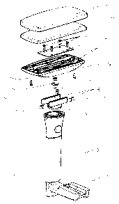
Figure 1 shows an armrest according to the invention
in an exploded illustration,
Figure 2 shows a plan view of the guide housing, and
Figure 3 shows a plan view of an armrest according to
the invention with an illustration of the
various movement possibilities for the arm
support.
METHODS OF IMPhEMENTING THE INVENTION
Figure 1 illustrates a carrier 1 on which a s_Leeve 2 is
arranged for sliding action. The carrier 1 is connected

CA 02440490 2003-09-08
- 4 -
to a seat flange 3, which is fastened on the r_hair (not
shown). The seat flange 3 has two slots and can be
displaced transversely to the seat direction. The seat
direction here is the direction from the backrest to
the front edge of the chair. The height of the armrest
can be adjusted by means of the sleeve 2 sliding on the
carrier 1. These technical rr~easures are all known per
se and will thus not be explained in any more detail.
The rotary bearing 5 is provided at the top end of the
sleeve 2. The rotary part 4 is mounted in a rotatable
manner in said bearing 5. The rotary part 4 has the
guide noses 6, which are connected integrally to the
rotary part 4. The rotary part 4 is screwed in the
rotary bearing 5 by the central screw 16.
Elastic latching protrusions 15 are accommodated in
recesses of the rotary part 4 and correspond with
notches on the inner circumference of the rotary
bearing 5. In the installed state, the rotary part 4 is
thus fixed in position, during rotation, wherever the
latching protrusions 15 end up in a notch.
In the installed state, the guide noses 6 er?.gage from
beneath in the two guides 7 in the guide housing 12. A
retaining plate 8 is provided on the other side of the
guides 7. This retaining plate is fastened on the guide
noses 6 by means of the retaining screws 9. The housing
screws 23 are used to fasten the guide housing 12 on
the carrying panel 10, which bears the foamed-on pads
11.
In the installed state, the underside of the guide
housing 12 slides between the two guide noses 6 on the
surface of the rotary part 4. In this case, the arm
support is displaced in the longitudinal or seat
direction. In order for it also to be possible for_ this
displacement to take place in fixed latching positions,
the horizontal latching protrusions 14 are provided in

CA 02440490 2003-09-08
- 5 -
a rotary part 4, and notches are provided on the
underside of the guide housing 12. Fixed latching
positions are thus produced whenever the expansible
latching protrusions 14 end up in a notch an the
underside of the guide housing 12.
The details of the guide housing 12 are illustrated
again more specifically in Figure 2. The two
eccentrically located guides 7 in particular can better
be seen. It is also possible to see the bores 18,
through which the housing screws 13 are screwed into
the carrying panel 10. The rotary bodies and
crosspieces (not designated) form a ske:Leton for
stabilizing the guide housing 12. This comprises a
plastic injection moulding, preferably made of
PAfpolyamide.
Figure 3 shows the pad 11 from above i:c~ various
positions. As can be seen, the axis of rotation 17,
that is the centre axis of the rotary part 4, is
located eccentrically in relation to the axis of
symmetry of the pad 11 which runs in the seat
direction.
The pad 11 can be displaced 7_ongitudinally in direction
B. This movement is made possible by the sliding
movement in the guides 7. It may also be rotated,
however, about the axis 17 in accordance with the
double arrow A. This rotation is made possible by the
rotary part 4. Finally, however, it is also possible
for the carrier 1 to be moved in direction C by means
of the seat flange 3.
With all these movement possibilities, the result is
not just a large number of adjustments for_ the arm
support with the pad 11; the eccentricity of the guides
7 also makes possible a large number of clear distances
between the two arm supports of a char.

CA 02440490 2003-09-08
- 6 -
The armrest according to the invention preferably
consists of the following material:
The carrier 1 and seat flange 3 consist of
injection-moulded plastic, the sleeve 2, rotary part 4
and housing 12 consist of injection-moulded plastic,
preferably PA, the retaining plate 8 is a punched part
made of sheet metal, and the carrying panel 10 with pad
11 is PA with a PUR covering. The latching protrusions
14 and 15 consist of steel with resilient elements made
of PUR.

CA 02440490 2003-09-08
List of designations
1 Carrier
2 Sleeve
3 Seat flange
4 Rotary part '
5 Rotary bearing
6 Guide noses
7 Guide
8 Retaining plate
9 Retaining screws
10 Carrying panel
11 Pad
12 Guide housing
13 Housing screws
14 Expansible latching protrusions
15 Rotary latching protrusions
16 Fastening screw for rotary part
17 Axis of rotation
24 18 Bores

Representative Drawing
A single figure which represents the drawing illustrating the invention.
Administrative Status

2024-08-01:As part of the Next Generation Patents (NGP) transition, the Canadian Patents Database (CPD) now contains a more detailed Event History, which replicates the Event Log of our new back-office solution.

Please note that "Inactive:" events refers to events no longer in use in our new back-office solution.

For a clearer understanding of the status of the application/patent presented on this page, the site Disclaimer , as well as the definitions for Patent , Event History , Maintenance Fee  and Payment History  should be consulted.

Event History

Description Date
Inactive: Dead - Final fee not paid 2012-06-13
Application Not Reinstated by Deadline 2012-06-13
Deemed Abandoned - Failure to Respond to Maintenance Fee Notice 2011-09-08
Deemed Abandoned - Conditions for Grant Determined Not Compliant 2011-06-13
Notice of Allowance is Issued 2010-12-13
Letter Sent 2010-12-13
Notice of Allowance is Issued 2010-12-13
Inactive: Approved for allowance (AFA) 2010-12-09
Amendment Received - Voluntary Amendment 2010-08-03
Inactive: S.30(2) Rules - Examiner requisition 2010-02-18
Letter Sent 2008-10-27
Request for Examination Received 2008-09-03
Amendment Received - Voluntary Amendment 2008-09-03
All Requirements for Examination Determined Compliant 2008-09-03
Request for Examination Requirements Determined Compliant 2008-09-03
Inactive: IPC from MCD 2006-03-12
Inactive: Filing certificate correction 2004-07-27
Inactive: Office letter 2004-06-02
Inactive: Filing certificate - No RFE (English) 2004-05-31
Application Published (Open to Public Inspection) 2004-04-04
Inactive: Cover page published 2004-04-04
Inactive: Correspondence - Transfer 2004-02-04
Letter Sent 2004-01-23
Inactive: Single transfer 2003-12-04
Inactive: First IPC assigned 2003-11-03
Inactive: Courtesy letter - Evidence 2003-10-14
Inactive: Filing certificate - No RFE (English) 2003-10-06
Filing Requirements Determined Compliant 2003-10-06
Application Received - Regular National 2003-10-03

Abandonment History

Abandonment Date Reason Reinstatement Date
2011-09-08
2011-06-13

Maintenance Fee

The last payment was received on 2010-08-24

Note : If the full payment has not been received on or before the date indicated, a further fee may be required which may be one of the following

  • the reinstatement fee;
  • the late payment fee; or
  • additional fee to reverse deemed expiry.

Please refer to the CIPO Patent Fees web page to see all current fee amounts.

Fee History

Fee Type Anniversary Year Due Date Paid Date
Application fee - standard 2003-09-08
Registration of a document 2003-12-04
MF (application, 2nd anniv.) - standard 02 2005-09-08 2005-08-31
MF (application, 3rd anniv.) - standard 03 2006-09-08 2006-08-25
MF (application, 4th anniv.) - standard 04 2007-09-10 2007-08-24
MF (application, 5th anniv.) - standard 05 2008-09-08 2008-08-28
Request for examination - standard 2008-09-03
MF (application, 6th anniv.) - standard 06 2009-09-08 2009-08-31
MF (application, 7th anniv.) - standard 07 2010-09-08 2010-08-24
Owners on Record

Note: Records showing the ownership history in alphabetical order.

Current Owners on Record
SEDUS STOLL AG
Past Owners on Record
KLAUS MAIER
MICHAEL KLASENER
THOMAS STENZEL
Past Owners that do not appear in the "Owners on Record" listing will appear in other documentation within the application.
Documents

To view selected files, please enter reCAPTCHA code :


To view images, click a link in the Document Description column. To download the documents, select one or more checkboxes in the first column and then click the "Download Selected in PDF format (Zip Archive)" or the "Download Selected as Single PDF" button.

List of published and non-published patent-specific documents on the CPD .

If you have any difficulty accessing content, you can call the Client Service Centre at 1-866-997-1936 or send them an e-mail at CIPO Client Service Centre.


Document
Description 
Date
(yyyy-mm-dd) 
Number of pages   Size of Image (KB) 
Claims 2010-08-03 2 70
Description 2003-09-08 7 277
Abstract 2003-09-08 1 22
Claims 2003-09-08 2 91
Drawings 2003-09-08 3 86
Representative drawing 2003-11-17 1 11
Cover Page 2004-03-09 2 43
Description 2010-08-03 7 262
Filing Certificate (English) 2003-10-06 1 159
Courtesy - Certificate of registration (related document(s)) 2004-01-23 1 106
Filing Certificate (English) 2004-05-31 1 158
Reminder of maintenance fee due 2005-05-10 1 110
Reminder - Request for Examination 2008-05-12 1 126
Acknowledgement of Request for Examination 2008-10-27 1 190
Commissioner's Notice - Application Found Allowable 2010-12-13 1 164
Courtesy - Abandonment Letter (NOA) 2011-09-06 1 164
Courtesy - Abandonment Letter (Maintenance Fee) 2011-11-03 1 173
Correspondence 2003-10-06 1 24
Correspondence 2004-06-02 1 13
Correspondence 2004-07-27 3 62