Note: Descriptions are shown in the official language in which they were submitted.
CA 02440495 2003-09-11
1
Laser Pulmonary Vein Isolation
BACKGROUND OF THE INVENTION
Field of the Invention.
(0001] This invention relates to methods and apparatus for the medical
treatment of
disease of the heart. More particularly, this invention relates to a method
and apparatus for
treating cardiac arrhythmias by ablating in a vicinity of pulmonary venous
tissue.
Description of the Related Art.
(0002] Tissue ablation from the inner walls of hollow viscera of the body
generally,
and the vascular system in particular, has been found to be useful in the
treatment of various
medical conditions. Technological developments in intravascular catheters,
manipulative in-
struments adapted to intravascular catheters, and catheter localization
techniques have espe-
cially benefited the field of cardiology. Percutaneous transcatheter ablation
has been used suc-
cessfully in the treatment of conduction defects and arrhythmias of various
types. Today, atria]
tachyarrhythmias are a common application for ablative therapy.
(0003] Various ablative modalities have been employed in the past, such as
ablation
by direct heating. Energy can be conducted to the target tissue using various
modalities, such
as ultrasound, laser, resistive heating, and radiofrequency energy.
(0004] One ablative approach is the so-called "maze" technique. In general,
the maze
procedure attempts to block abnormal conduction patterns in the left atrium by
establishing a
maze-like pattern of linear lesions in the left atrial wall.
(0005] Atrial arrhythmias are known to be associated with abnormal electrical
activity
of tissue foci in the vicinity of the pulmonary veins, especially the superior
pulmonary veins.
Various ablative treatments of such foci have been attempted. For example, the
production of
linear atrial lesions by radiofrequency ablation, in combination with ablation
of suspected ar-
rhythmogenic foci has been performed using transcatheter techniques.
(0006] More recently, circumferential lesions at or near the ostia of the
pulmonary
veins have been created to treat atrial arrhythmias. U.S. Patent Nos.
6,012,457 and 6,024,740,
both to Lesh, disclose a radially expandable ablation device, which includes a
radiofrequency
electrode. Using this device, it is proposed to deliver radiofrequency energy
to the pulmonary
CA 02440495 2003-09-11
2
veins in order to establish a circumferential conduction block, thereby
electrically isolating the
pulmonary veins from the left atrium.
(0007] U.S. Patent No. 5,468,239 to Tanner et al. describes a circumferential
laser as-
sembly, adapted, for example, to be placed in the urethral canal such that a
transurethral resec-
tion of benign prostatic hypertrophy may be performed.
(0008] Radiofrequency ablation using multiple contiguous circumferential
points,
guided by electro-anatomical mapping is proposed in the document,
Circumferential
Radiofrequency Ablation of Pulmonary Vein Ostia: A New Anatomic Approach for
Curing
Atrial Fibrillation, Pappone C, Rosanio S, Oreto G, Tocchi M, Gugliotta F,
Vicedomini G,
Salvati A, Dicandia C, Mazzone P, Santinelli V, Gulletta S, Chierchia S,
Circulation 102:2619-
2628 (2000). It is emphasized that particular care must be exercised to ensure
that the ablation
sites are indeed contiguous; otherwise irregular electrical activity in the
pulmonary vein may
continue to contribute to atrial arrhythmia.
(0009] It has also been proposed to produce circumferential ablative lesions
using
ultrasound energy delivered via a cylindrical ultrasound transducer through a
saline-filled
balloon. This technique is described in the document, First Human Experience
With
Pulmonary Vein Isolation Using a Through-the-Balloon Circumferential
Ultrasound Ablation
System for Recurrent Atrial Fibrillation, Natale A, Pisano E, Shewchik J, Bash
D, Fanelli R,
MD; Potenza D; Santaelli P; Schweikert R; White R; Saliba W; Kanagaratnam L;
Tchou P;
Lesh M, Circulation 102:1879-1882 (2000). Ablation times in the order of 2
minutes are
reported.
(0010) A known drawback in the use of ultrasound energy for cardiac tissue
ablation is
the difficulty in controlling the local heating of tissue. There are tradeoffs
between the clinical
desire to create a sufficiently large lesion to effectively ablate an abnormal
tissue focus, or
block an aberrant conduction pattern, and the undesirable effects of excessive
local heating. If
the ultrasound device creates too small a lesion, then the medical procedure
could be less ef-
fective, or could require too much time. On the other hand, if tissues are
heated excessively
then there could be local charring effects due to overheating. Such overheated
areas can de-
velop high impedance, and may form a functional barrier to the passage of
heat. The use of
slower heating provides better control of the ablation, but unduly prolongs
the procedure.
CA 02440495 2011-03-01
3
[00111 In consideration of these, and other factors, it is appropriate, in
designing a
practical energy emitter, to consider the amplitude of the energy signal, the
amount of time re-
quired for the energy application, the size of the emitter, and the contact
area, as well as ease of
positioning, withdrawal, and repositioning of the device so as to be able to
conveniently pro-
duce multiple lesions during the same medical procedure.
[00121 Previous approaches to controlling local heating include the inclusion
of ther-
mocouples within the electrode and feedback control, signal modulation, local
cooling of the
catheter tip, and fluid assisted techniques, for example perfusion of the
target tissue during the
energy application, using chilled fluids. Typical of the last approach is
Mulier, et al. U.S. Pat-
ent No. 5,807,395.
[00131 Publications which describe various medical techniques of interest
include:
[00141 Scheinman MM, Morady F. Nonpharmacological Approaches to Atrial Fibril-
lation. Circulation 2001;103:2120-2125.
[00151 Wang PJ, Homoud MK, Link MS, Estes III NA. Alternate energy sources for
catheter ablation. Curr Cardiol Rep 1999 Jul;1(2):165-171.
[00161 Fried NM, Lardo AC, Berger RD, Calkins H, Halperin HR. Linear lesions
in
myocardium created by Nd:YAG laser using diffusing optical fibers: in vitro
and in vivo re-
sults. Lasers Surg Med 2000;27(4):295-304.
[0017] Keane D, Ruskin J, Linear atrial ablation with a diode laser and fiber
optic
catheter. Circulation 1999; 100:e59-e60.
[00181 Ware D, et al., Slow intramural heating with diffused laser light: A
unique
method for deep myocardial coagulation. Circulation; March 30, 1999; pp. 1630-
1636.
[00191 Other medical technologies of interest are described in U.S. Patent
Nos.
5,891,134 to Goble et al., 5,433,708 to Nichols et at., 4,979,948 to Geddes et
al., 6,004,269 to
Crowley et al., 5,366,490 to Edwards et al., 5,971,983, 6,164,283, and
6,245,064 to Lesh,
6,190,382 to Ormsby et al., 6,251,109 and 6,090,084 to Hassett et al.,
5,938,600 to Swartz et
al., 6,064,902 to Haissaguerre et al., and U.S. Patent No. 6,117,101 to
Diederich et at.
[0020]
BIO-142
CA 02440495 2003-09-11
4
SUMMARY OF THE INVENTION
[00211 It is therefore a primary object of some aspects of the present
invention to pro-
vide improved apparatus and method for electrically isolating the pulmonary
vein by accom-
plishing a circumferential conduction block surrounding the pulmonary vein
ostium in a single
ablation application of laser light energy.
[0022) It is another object of some aspects of the present invention to reduce
the time
required to perform isolation of the pulmonary veins using a laser.
(0023) A catheter introduction apparatus provides an optical assembly for
emission of
laser light energy. In one application, the catheter and the optical assembly
are introduced per-
cutaneously, and transseptally advanced to the ostium of a pulmonary vein. An
anchor such as
an anchoring balloon is expanded to center a mirror in front of the ostium of
the pulmonary
vein, such that light energy is reflected from the mirror circumferentially
onto the wall of the
pulmonary vein when a laser light source is energized. A circumferential
ablation lesion is pro-
duced around the ostium of the pulmonary vein, which effectively blocks
electrical propagation
between the pulmonary vein and the left atrium.
(0024) The invention provides a method for electrically isolating a cardiac
chamber,
including the steps of introducing an optical assembly at a pulmonary vein
proximate its os-
tium, anchoring the optical assembly at the pulmonary vein, and thereafter
conducting laser
light energy in a path extending from the optical assembly to a
circumferential ablation region
of the pulmonary vein.
(00251 According to an aspect of the method, the path avoids the anchor.
[00261 According to another aspect of the method, conducting the laser light
energy is
performed by directing the laser light energy into a circumferential line that
intersects the abla-
tion region.
(0027) In another aspect of the method, the anchor is a balloon, and anchoring
is per-
formed by expanding the balloon to engage the pulmonary vein.
[0028) In a further aspect of the method, the optical assembly is introduced
via the
fossa ovalis, and preliminary laser light energy is directed onto the fossa
ovalis to ablate tissue
thereof to facilitate passage of the optical assembly therethrough.
[0029) In yet another aspect of the method, conducting the laser light energy
is per-
formed in exactly one application.
CA 02440495 2011-03-01
[0030] In still another aspect of the method, conducting the laser light
energy is per-
formed in a series of pulses.
[00311 According to another aspect of the method, the duration of each of the
pulses is
less than 100 milliseconds.
[0032] In an additional aspect of the method, introducing the optical assembly
is per-
formed by disposing the optical assembly on an intravascular catheter, and
passing the distal
portion of the intravascular catheter through a blood vessel into the heart.
[0033] In one aspect of the method, conducting the laser light energy also
includes re-
flecting the laser light energy.
[0034] According to a further aspect of the method, reflecting the laser light
energy in-
cludes disposing a mirror in a path of the laser light energy external to the
anchor.
[0035] According to yet another aspect of the method, reflecting the laser
light energy
includes disposing a light-reflective coating on an external surface of the
anchor and reflecting
the laser light energy from the light-reflective coating.
[0036]
[0037] The invention provides an apparatus for electrically isolating a
cardiac cham-
ber, including an intravascular catheter adapted for introduction into a
pulmonary vein proxi-
mate an ostium thereof, an anchor disposed at a distal end of the catheter for
fixation of the
catheter tip at the pulmonary vein,'and an optical assembly for conducting
laser light energy in
a path extending to a circumferential ablation region of the pulmonary vein.
[0038] According to an aspect of the apparatus, the optical assembly is in a
non-
contacting relationship with the anchor.
[0039] According to yet another aspect of the apparatus, the path avoids the
anchor.
[0040] According to an additional aspect of the apparatus, the optical
assembly in-
cludes an optical fiber for conducting the laser light energy from a light
source, a lens disposed
at an exit face of the optical fiber, and a reflector disposed in the path
external to the anchor for
directing the laser light energy into a circumferential line that intersects
the ablation region.
[00411 According to an additional aspect of the apparatus, the lens is a
graded index
lens.
[0042] According to one aspect of the apparatus, the reflector is a parabolic
mirror.
BIO-142
CA 02440495 2011-03-01
6
[0043] According to another aspect of the apparatus, the reflector is a light
reflecting
external surface of the anchor.
[0044] According to one aspect of the apparatus, the anchor includes a balloon
that in-
flates to engage the pulmonary vein.
[0045] According to an additional aspect of the apparatus, the balloon is
bilobate.
[0046] According to one aspect of the apparatus, a proximal portion of the
balloon is
more expanded than a distal portion of the balloon in an inflated state
thereof.
[0047] According to another aspect of the apparatus, the laser light energy is
applied to
the ablation region in exactly one application.
[0048] According to a further aspect of the apparatus, the laser light energy
is applied
to the ablation region in a series of pulses.
[0049] According to yet another aspect of the apparatus, the duration of each
of the
pulses is less than 100 milliseconds.
[0050] According to still another aspect of the apparatus, the laser light
energy has a
wavelength of about 1.3 microns.
BRIEF DESCRIPTION OF THE DRAWINGS
[0051] For a better understanding of these and other objects of the present
invention,
reference is made to the detailed description of the invention, by way of
example, which is to
be read in conjunction with the following drawings, wherein:
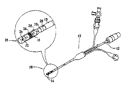
[0052] Fig. 1 illustrates a therapeutic catheter that is constructed and
operative in ac-
cordance with a preferred embodiment of the invention;
[0053] Fig. 2 is an enlarged schematic illustration of the distal end of the
cathe-
ter shown in Fig. I with an inflation balloon expanded, and an optical fiber
and associated op-
tics in place, in accordance with respective preferred embodiments of the
present invention;
[0054] Fig. 3 is a schematic sectional view of a laser subassembly employing a
para-
bolic mirror, taken along the axis of a catheter in accordance with a
preferred embodiment of
the invention;
[0055] Fig. 4 is a schematic sectional view of a laser subassembly employing a
light-
reflective coating taken along the axis of a catheter in accordance with an
alternate embodi-
ment of the invention;
BIO-142
CA 02440495 2003-09-11
7
[00561 Fig. 5 is a flow chart of a method for electrically isolating pulmonary
veins,
which is operative in accordance with a preferred embodiment of the invention;
100571 Fig. 6 schematically illustrates certain aspects of a method of
intracardiac
catheter access during a first phase of the method shown in Fig. 5;
100581 Fig. 7 schematically illustrates certain aspects of a method of
intracardiac
catheter access during a second phase of the method shown in Fig. 5; and
[00591 Fig. 8 schematically illustrates certain aspects of a method of
intracardiac
catheter access during a third phase of the method shown in Fig. 5.
DETAILED DESCRIPTION OF THE INVENTION
[0060] In the following description, numerous specific details are set forth
in order to
provide a thorough understanding of the present invention. It will be apparent
to one skilled in
the art, however, that the present invention may be practiced without these
specific details. In
other instances, well known circuits, control logic, and other apparatus have
not been shown in
detail in order not to unnecessarily obscure the present invention.
100611 Turning now to the drawings, reference is made to Fig. 1, which
illustrates a
medical device that is constructed and operative in accordance with a
preferred embodiment of
the invention. An intravascular catheter 10 has a proximal end 12 and a distal
end 14. The dis-
tal end 14 is provided with at least one seal 16, and optionally a second seal
18. The
seals 16, 18 are preferably inflatable balloons, made from rubber,
polyurethane, or a similar
elastic material. The catheter 10 has one or more lumens, which conduct fluid
for inflating and
deflating the seals 16, 18. One of the lumens terminates in a port 20, and is
useful for injection
of fluids and withdrawal of blood as may be required during use. Other lumens
are provided
for passage of guidewires and instruments therethrough. An inflatable
anchoring balloon 22,
shown in a deflated condition, is located distal to the seals 16, 18. The
catheter 10 also has a
coaxial guidewire lumen 24.
100621 Reference is now made to Fig. 2, which is a schematic enlarged view of
the
distal end 14 of a catheter that is constructed and operative in accordance
with a preferred em-
bodiment of the invention, similar to the catheter 10 (Fig. 1), in which like
elements are given
like reference numerals. Disposed near the distal end 14 of the catheter 10 is
a laser subassem-
bly 26, which includes an optical fiber 28, shown in a position proximate the
lumen 24, which
conveys laser light through a lens 30 to a mirror (Fig. 3) or a light-
reflective coating (Fig. 4),
CA 02440495 2003-09-11
8
which in turn reflects the laser light circumferentially onto a target. The
laser subassembly 26
is preferably disposed external to and in a non-contacting relationship with
the anchoring bal-
loon 22. Thus in many embodiments, the anchoring balloon 22 need not directly
support the
laser subassembly 26, and is excluded from the laser light path. An advantage
of this arrange-
ment is that standard catheter balloons can be used in the catheter 10.
100631 Introduced slidably via the lumen 24, the optical fiber 28 extends to
and is con-
nected proximally to a suitable external laser light source 32. For some
applications, a mirror
34 is rigidly fixed in position with respect to the catheter body or a
structural component
thereof. It will be appreciated that whereas the mirror 34 is shown by way of
illustration, other
optical elements known in the art (e.g., lenses) may also be configured for
use with some em-
bodiments of the invention.
100641 In a preferred embodiment, the active sites to be ablated are
identified using the
location and mapping system disclosed in commonly assigned U.S. Patent No.
5,840,025,
which is herein incorporated by reference. Certain components of the location
and mapping
system are incorporated into the distal end 14 of the catheter 10, namely a
sensor 36 and a
transmitting antenna 38 (Fig. 1), which can be a dipole antenna. The sensor 36
detects local
electrical activity of the heart, and the antenna 38 transmits signals to a
plurality of receiving
antennae (not shown) which are placed on the body surface of a patient during
use. The distal
end 14 can be radio-opaque, in order to facilitate its localization by
conventional radiographic
techniques, alternatively or in addition to the system disclosed in the above-
noted U.S. Patent
No. 5,840,025.
100651 In embodiments in which the system disclosed in the above-noted U.S.
Patent
No. 5,840,025 is not used, the sensor 36 performs conventional monitoring of
local electrical
activity, and the antenna 38 can be omitted.
100661 The anchoring balloon 22 is inflated, and preferably has a large-radius
proxi-
mal lobe or segment 40, and a small-radius distal lobe or segment 42.
Typically the anchoring
balloon 22 measures 1 cm in length and has a caliber of about 2.7 nun. (8
French) when unin-
flated, expanding to 3 - 4 cm when inflated. The bilobate configuration of the
anchoring bal-
loon 22 aids in securely positioning the anchoring balloon 22 within the
ostium of a pulmonary
vein. Alternatively the anchoring balloon 22 can be pyriform, ellipsoidal, or
otherwise con-
structed, preferably such that its proximal portion is more radially expanded
than its distal por-
CA 02440495 2003-09-11
9
Lion. The anchoring balloon 22 is constructed of conventional materials.
Proximally, a connec-
tion between the optical fiber 28 and the laser light source 32 is
illustrated.
100671 In some embodiments, the anchoring balloon 22 is coated with a light-
reflective coating (Fig. 4), and is positioned so as to reflect the light from
the laser subassem-
bly 26 to the endocardial wall and thereby facilitate the circumferential
ablation around the
pulmonary vein. In these embodiments, the mirror 34 is typically omitted, and
a light-reflective
coating directs the laser light circumferentially and directly towards the
ablation zone.
100681 Reference is now made to Fig. 3, which is a schematic sectional view of
the la-
ser subassembly 26 (Fig. 2) taken along the axis of the optical fiber 28 in
accordance with a
preferred embodiment of the invention. The description of Fig. 3 should be
read in conjunction
with Fig. 2, in which like elements are given like reference numerals. The
optical fiber 28 is
coupled at its exit face to a graded index (GRIN) rod lens 44, which serves as
a relay lens for
light passing through the optical fiber 28. As shown by an exemplary ray 46,
light exiting the
lens 44 strikes a mirror 48 that is disposed between the lens 44 and the
anchoring balloon 22,
and is then reflected. The mirror 48 is a 360 degree parabolic mirror, which
is symmetric about
the axis of the catheter 10 (Fig. 1), so that when the apparatus is
positioned, the reflected light
strikes the ablation zone as a circumferential beam.
[0069) Reference is now made to Fig. 4, which is a schematic sectional view of
a laser
subassembly taken along the axis of the optical fiber 28 in accordance with an
alternate em-
bodiment of the invention. The description of Fig. 4 should be read in
conjunction with Fig. 2
and Fig. 3, in which like elements are given like reference numerals. The
arrangement shown
in Fig. 4 is similar to that of Fig. 3, except that the mirror is omitted.
Instead a light-reflective
coating 50 is disposed on the external surface of the anchoring balloon 22. As
shown by an ex-
emplary ray 52, light exiting the lens 44 strikes the light-reflective coating
50, and is then re-
flected. When the apparatus is positioned, the reflected light strikes the
ablation zone as a cir-
cumferential beam.
100701 Reference is now made to Fig. 5, which is a flow chart of a method for
electri-
cally isolating pulmonary veins, which is operative in accordance with a
preferred embodiment
of the invention. The description of Fig. 5 should be read in conjunction with
Figs. 1, Fig. 3,
and Fig. 4.
CA 02440495 2003-09-11
[0071] In initial step 54 routine preparation of a subject (not shown) and
equipment are
accomplished. This includes attachment of various monitoring and grounding
leads, as may be
required for electrophysiological monitoring of the procedure and for the
operation of the
above-noted location and mapping system.
[0072] Next, at step 56, a series of events begins, ultimately leading to the
positioning
of the catheter 10 and the laser subassembly 26 at the ostium of a pulmonary
vein. Step 56 is
typically conventional. In a preferred approach, the venous system is accessed
using the well-
known Seldinger technique, in which an introducer sheath is positioned in a
peripheral vein,
typically a femoral vein. A guiding sheath is introduced through the
introducer sheath, and is
advanced via the inferior vena cava into the right atrium. Then, using a
Brockenbrough needle,
the fossa ovalis of the interatrial septum is punctured, and the puncture
dilated if necessary.
The Brockenbrough needle is withdrawn, and the guiding sheath placed in the
left atrium. Al-
ternatively, the ablation catheter is energized as it contacts the interatrial
septum, usually at the
fossa ovalis, in order to ablate a portion of the fossa ovalis. Ablation of
septal tissue eases the
passage of the catheter through the septum, reduces the amount of hardware
used, and shortens
the procedure, as it is not necessary to pass a dilator through the fossa
ovalis. Ablation of septal
tissue typically requires a power output of less than 70 watts. It is also
possible to access the
left atrium via the superior vena cava, or to use a retrograde intra-arterial
technique.
[0073) Next, in step 58 a guidewire is advanced through the guiding sheath,
through
the left atrial chamber, into a pulmonary vein.
[0074] The order in which the specific pulmonary veins are visited and treated
is arbi-
trary, but it is preferable to concentrate first on the two superior pulmonary
veins, in which the
muscular sleeves are more prominent than in the inferior pulmonary veins.
Thereafter the infe-
rior pulmonary veins may be isolated. Typically, an ablation procedure
involves the isolation
of all four pulmonary veins.
100751 Reference is now made to Fig. 6, which schematically illustrates
certain aspects
of the method of electrical pulmonary vein isolation in accordance with a
preferred embodi-
ment of the invention. The description of Fig. 6 should be read in conjunction
with Fig. 5.
Fig. 6 represents the status at the completion of step 58 (Fig. 5). A cutaway
view of a left atrial
chamber 60 includes a right superior pulmonary vein 62 and a left superior
pulmonary vein 64,
whose ostium 66 is indicated. The view of Fig. 6 also includes a right
inferior pulmonary
CA 02440495 2003-09-11
11
vein 68, and a left inferior pulmonary vein 70. A conventional guiding sheath
72 has a distal
end 74 which has been positioned on the left atrial side of an interatrial
septum 76. A conven-
tional guidewire 78 extends through the lumen of the guiding sheath 72, into
the lumen of the
left superior pulmonary vein 64. It will be understood that while the
guidewire 78 is shown in
relation to the left superior pulmonary vein 64, the technique is equally
applicable to the other
pulmonary veins.
100761 Referring again to Fig. 5, at step 80 the guiding sheath is withdrawn,
and an
ablation catheter is slidably tracked over the guidewire, using the guidewire
lumen of the
catheter. The catheter is advanced into the left atrium. While maneuvering the
catheter in the
heart, its position is preferably monitored by the location and mapping system
disclosed in the
above-noted U.S. Patent No. 5,840,025, or alternatively by conventional
imaging modalities.
The anchoring balloon of the catheter is deflated during the positioning
maneuver. The tip of
the catheter is advanced until it is located at the ostium of a pulmonary
vein, such that a first
segment of the catheter's anchoring balloon, which is substantially the
balloon's proximal
third, is disposed in the left atrium, and a second segment of the anchoring
balloon, composed
of its remaining distal portion, lies within the lumen of the pulmonary vein.
10077] Reference is now made to Fig. 7, which schematically illustrates
certain aspects
of the method of electrical pulmonary vein isolation in accordance with a
preferred embodi-
ment of the invention. The description of Fig. 7 should be read in conjunction
with Figs. 5 and
6. Fig. 7 represents the status at the completion of step 80 (Fig. 5).
Structures in Fig. 7 which
are identical to corresponding structures in Fig. 6 have been given like
reference numerals. The
shaft of the catheter 10 extends through the interatrial septum 76. A portion
of the anchoring
balloon 22 is disposed across the ostium 66 of the left superior pulmonary
vein 64. The
guidewire 78 is still in position. The optical fiber 28 has not yet been
introduced. During
placement, the anchoring balloon 22 is deflated.
[0078] Referring again to Fig. 5, at step 82 the anchoring balloon 22 is
inflated to fix
the catheter 10 in position. The guidewire 78 is withdrawn, and the optical
fiber 28 is intro-
duced into the catheter 10 via the lumen 24, or is pre-fixed to the distal end
of the catheter 10.
The mirror 34 is positioned proximal to the anchoring balloon, to be in a
position to reflect the
laser output of the optical fiber 28, such that the light essentially
simultaneously impinges upon
an entire ring in or adjacent to the inner lining of the pulmonary vein.
Perfusion of the area
CA 02440495 2011-03-01
12
through one of the catheter ports may be employed during step 82 to minimize
stasis of blood
in the region.
[0079] In step 84, once the position of the mirror 34 is confirmed, the laser
light
source 32 is energized, and light energy is conducted from the optical fiber
28 to the target tis-
sue.
[0080] Reference is now made to Fig. 8, which schematically illustrates
certain aspects
of the method of electrical pulmonary vein isolation in accordance with a
preferred embodi-
ment of the invention. The description of Fig. 8 should be read in conjunction
with Figs. 5 and
7, in which like reference numbers denote the same element throughout. Fig. 8
represents the
status at step 84 (Fig. 5). The anchoring balloon 22 is inflated, and the
optical fiber 28 has been
introduced such that its distal end is at the distal end 14 of the catheter
10. The mirror 34 is po-
sitioned in readiness for reception of laser light from the optical fiber 28.
[0081] Referring again to Fig. 5, the transfer of laser light energy from the
optical fi-
ber 28 to the pulmonary vein in step 84 preferably occurs in a single,
relatively short applica-
tion. The output of the laser light source 32 (Fig. 2) is preferably infrared
light at about 1.3 mi-
crons. This wavelength has a low absorption coefficient in water and is
therefore suitable for
transfer of energy to the ablation zone. It is recommended to deliver short
pulses of energy of a
few milliseconds each. Pulses less than 100 milliseconds are most preferred.
The energy appli-
cation may be controlled in response to continuous electrophysiological
monitoring, an end
point being reached when conduction block is confirmed across the line of
ablation. Alterna-
tively, it may continue for a duration predetermined to cause conduction
block, substantially
without feedback. In this latter case, electrophysiological data recorded
while the catheter is
still in position are preferably analyzed, so as to determine whether a second
period of energy
application is desired.
[0082] Upon completion of the ablation, in step 86 the anchoring balloon is
deflated
and the mirror 34 retracted. The tip of the catheter is withdrawn into the
left atrial chamber.
The optical fiber 28 is also withdrawn from the catheter 10, if appropriate.
[0083] Next, at decision step 88, a test is made to determine if more
pulmonary veins
remain to be electrically isolated. If the determination is affirmative then
control proceeds to
step 90, where the next pulmonary vein is selected. Control then returns to
step 58.
BI0-142
CA 02440495 2003-09-11
13
100841 If the determination at decision step 88 is negative, then control
proceeds to fi-
nal step 92. The anchoring balloon is deflated, and the entire apparatus
withdrawn from the pa-
tient. The procedure thereupon terminates.
100851 It will be appreciated by persons skilled in the art that the present
invention is
not limited to what has been particularly shown and described hereinabove.
Rather, the scope
of the present invention includes both combinations and sub-combinations of
the various fea-
tures described hereinabove, as well as variations and modifications thereof
that are not in the
prior art which would occur to persons skilled in the art upon reading the
foregoing description.