Note: Descriptions are shown in the official language in which they were submitted.
CA 02440655 2003-09-12
272/132
WIND POWERED ENERGY GENERATING MACHINE
[0001] This application claims the benefit of United
States provisional patent application No. 60/410,782,
filed September 13, 2002.
Background of the Invention
[0002] This invention relates to a machine for
generating energy from a wind source. More
particularly, this invention relates to a machine
having a rotor that is caused to rotate around a
vertical axis by a wind source. The rotor may be
coupled to a dynamo-electric generator in order to
produce electric power for downstream consumption.
[0003] Currently, machines for generating energy
from wind sources can include large wind turbines
mounted at wind sites, along with various deflectors
placed upstream of the turbine. Such arrangements can
be difficult to install at the wind sites, as the
placement of the various deflectors can be complex. In
addition, such an arrangement can be unaesthetic and
can lessen the beauty of the landscape at the wind
site.
CA 02440655 2003-09-12
- 2 -
[0004] Accordingly, it would be desirable to provide
a machine for generating energy from a wind source
having a casing structure within which a rotor having a
vertical axis of rotation is positioned.
Summary of the Invention
[0005] In accordance with the present invention, a
machine for generating energy from a wind source is
provided having a casing structure within which a rotor
having a vertical axis of rotation is positioned.
[0006] The solutions of the present invention
simplify the construction process of the machinery and
its installation at a wind site. Furthermore, the
machinery may be adjusted to optimize the power
extraction from a wind source, and achieves a minimal
ecological impact when installed at the wind site. The
machinery is applicable for a wide range of power
rating consumptions (e. g., from ratings of domestic
applications to ratings of primary wind power
stations).
[0007] In some embodiments of the present invention,
the machine for generating usable energy from a wind
source has a casing structure. A rotor having a blade
structure is positioned within the casing structure and
has a substantially vertical axis of rotation. The
casing structure may define an air inlet upstream of
the rotor that is oriented with respect to a prevailing
wind direction and an air outlet downstream of the
rotor. The casing structure may have a main passage
through which air flows and interacts with the blade
structure. The casing structure may have first and
second side passages that are delimited by first and
second sidewalls of the casing structure, respectively.
CA 02440655 2003-09-12
- 3 -
The first and second side passages may converge toward
one another near the air outlet forming a zone of low
pressure downstream of the rotor.
[0008] Further features of the invention, its nature
and various advantages will be more apparent from the
accompanying drawings and the following detailed
description.
Brief Description of the Drawings
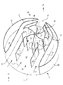
[0009] FIG. 1 is a partial perspective view of the
energy generating machine of the present invention,
with certain parts removed to show other parts that
would otherwise be hidden.
[0010] FIG. 2 is a view as seen from direction 2--2
of FIG. 1.
[0011] FIG. 3 is an enlargement of portion 3 of
FIG. 2.
[0012] FIG. 4 is a sectional view as seen from
direction 4--4 of FIG. 2, and which also shows the
parts which have been removed in FIG. 1.
Detailed Description of the Invention
[0013] As shown in FIGS. 1-3, rotor 10 is located in
passage 12 for rotation around vertical axis 14 in
direction 15 when driven by a wind source (e.g., a
natural wind source). Vertical axis 14 is
substantially perpendicular to upper cover plate 16 and
lower cover plate 18 of general casing structure 20.
Upper cover plate 16 and lower cover plate 18 may be
substantially horizontal, and therefore parallel to a
ground plane that supports general casing structure 20.
(In FIG. 1, upper cover plate 16 is not shown in order
CA 02440655 2003-09-12
- 4 -
to show other parts of the machine that would otherwise
be hidden.)
[0014] Rotor 10 may include a blade structure. In
the example shown in the FIGS., the blade structure of
rotor 10 includes a plurality of blades 22 that are
cantilevered from rotation shaft 24. Blades 22 may be
panels having a concave configuration, as shown in the
FIGS. Blades 22 may have other configurations, such as
a spiral shape, to increase the power extraction from
the wind source. Passage 12 may be delimited laterally
by opposite side walls 26 and 28 and vertically by
upper and lower cover plates 16 and 18, respectively.
[0015] Side walls 26 and 28 extend from inlet
opening 30 of passage 12 to outlet opening 32 of
passage 12. Side walls 26 and 28 may be substantially
parallel to each other in portion 34 of passage 12,
while sidewalls 26 and 28 may converge towards each
other in portion 36 of passage 12. Inlet opening 30
faces a prevailing wind direction in order to collect
and achieve air flow F in portion 34 of passage 12.
[0016] In portion 34, the path of air flow F is
initially parallel to sidewalls 26 and 28. Air flow
deflector members, consisting of upstanding
panels 38-43, are spaced apart at predetermined
positions in portion 34 in order to partially surround
rotor 10 along a circular sector 46. Portions Fi of air
flow F are deflected by panels 38-43, thereby causing
the air particles of flow F to fill compartments 48 of
the rotor. Compartments 48 are delimited by blades 22
and upper and lower cover plates 16 and 18,
respectively. The configurations of panels 38-43
(shown as both concave and straight in the FIGS.), and
their orientation, cause the air particles to impinge
CA 02440655 2003-09-12
- 5 -
on the surfaces of blades 22 at predetermined angles.
The predetermined angles influence the resultant
driving force achieved on rotor 10 by the wind source.
The air particles that enter compartments 48 rotate
with rotor 10 and run along blades 22 until they are
discharged through passage 50. Thus, the air particles
lose their quantity of motion or energy in order to
drive rotor 10.
[0017] Narrow passages 52 and 54, which are
respectively delimited by sidewalls 26 and 28, are on
opposite sides of the circular sector 46 occupied by
panels 38-43. Upper and lower cover plates 16 and 18,
respectively, vertically delimit passages 52 and 54.
[0018] Upstanding casing structures 56 and 58 are
located in another circular sector 60 surrounding
rotor 10. Face 62 of casing structure 56, together
with panel 38, form passage 64. Similarly, face 66 of
casing structure 58, together with panel 43, form
passage 68. Face 70 of casing structure 56 surrounds a
portion of rotor 10. Similarly, face 72 of casing
structure 58 surrounds another portion of rotor 10.
Passage 50 is formed between face 74 and face 76.
Face 78 and sidewall 26 complete narrow passage 52.
Similarly, face 80 and sidewall 28 complete narrow
passage 54. Preferably, passage 50 is centered on
axis 82, and narrow passages 52 and 54 are spaced
symmetrically apart with respect to axis 82, as shown
in the FIGS.
[0019] By means of the described arrangement,
portions of air flow F that have not entered rotor 10
(see portions of air flow F referenced as F1 and FZ)
will run through narrow passages 52 and 54 to create a
low pressure region in portion 36. The low pressure
CA 02440655 2003-09-12
- 6 -
region in portion 36 induces the extraction of air
particles from rotor 10 through passage 50. The
extraction occurs when a compartment 48 of rotor 10 is
facing passage 50. The sectional size of passage 50
influences the average speed of the air particles when
moving with rotor 10. More particularly, a restricted
sectional size of passage 50, compared to the total
sectional size of passages formed by panels 38-43 on
sector 46, increases the average speed of the air
particles rotating with rotor 10. The increase in the
average speed of the air particles extracts more
rotation power for rotor 10, which consequently
increases the electric power that can be obtained for
downstream consumption.
[0020] The low pressure region 36 extends beyond
outlet opening 32 so that the air particles of flow F
are ultimately discharged from passage 32.
[0021] Rotor 10 is supported for rotation in
direction 15 by supporting shaft 24 in bearings 84
and 86, seated in upper cover plate 16 and lower cover
plate 18, respectively (see FIG. 4). Dynamo-electric
generator 88 may be coupled to shaft 24, as shown in
FIG. 4.
[0022] External plates 90 and 92, which have a
cylindrical shape, surround side walls 26 and 28. As a
result, general casing structure 20 has a homogenous
cylindrical appearance to the external observer. In
addition, the resulting cylindrical form of general
casing structure 20 presents low disruption to air flow
investing the entirety of general casing structure 20.
[0023] Lower case plate 18 may be provided with
wheels 94, which may be supported and guided by ground
rail 96. Ground rail 96 may be circular in order to
CA 02440655 2003-09-12
7 _
rotate lower case plate 18 around a vertical axis of
the machinery. Circular rack 98, which lines lower
cover plate 18 and is concentric to the vertical axis
of the machinery, may be engaged by pinion 100 of
motor 102. By rotation of motor 102, general casing
structure 20 may be rotated around the vertical axis of
the machinery to orient inlet opening 30 with respect
to a prevailing wind direction, thereby maximizing
power extraction from the wind source.
[0024] The prevailing wind direction may be sensed
by a wind direction sensor that supplies information
signals which may be used by a control and regulation
unit to drive motor 102, resulting in calculated
rotations that orient inlet opening 30 with respect to
the prevailing wind direction. The external
cylindrical form of general casing structure 20 offers
low air obstruction when rotating general casing
structure 20 around the vertical axis of the machinery
to orient inlet opening 30 with respect to the
prevailing wind direction.
[0025] Limiting the power extraction from the wind
source in situations of high wind speeds may be
achieved by rotating baffles 104 towards each other to
form a diverging passage for the air flow reaching and
passing through rotor 10. A rotated position of
baffles 104 is shown by the dashed lines in FIG. 2.
[0026] The inclusion of rotor 10 within general
casing structure 20 greatly reduces the noise level
that rotor 10 produces during rotation caused by the
wind source. Furthermore, protection grids (not shown)
may be installed across inlet opening 30 and outlet
opening 32 to prevent humans and animals from entering
passage 12. The protection grids would be visible and
CA 02440655 2003-09-12
_ g _
would present low air obstructions to the air flow F
needed in passage 12.
[0027] Higher power ratings of the machinery may be
achieved by increasing the overall sizes of rotor 10
and passage 12. The major increases in size can be in
the diameter of rotor 10 and in the plan dimensions of
passage 12. These alterations would result in a lower
height of general casing structure 20 with respect to
the height of traditional wind driven machinery having
the same power rating. An increase of the power
ratings can also be achieved by mounting multiple
units, such as the unit shown in FIG. 4, one above the
other in order to form a vertical column of small plan
occupancy.
[0028] The machine of the present invention may be
installed in various locations where it is desired to
produce electric power from a wind source. For
example, the machine of the present invention may be
installed on a roof of a tall building in an urban
setting, thereby taking advantage of the high winds
present at such a height and making efficient use of
available space.
[0029] Thus, a wind powered energy generating
machine is provided. One skilled in the art will
realize that the present invention can be practiced by
other than the described embodiments, which are
presented for purposes of illustration and not of
limitation, and that the present invention is limited
only by the claims which follow.