Note: Descriptions are shown in the official language in which they were submitted.
CA 02441087 2003-09-12
WO 02/084099 PCT/US02/11443
FILTER ASSEMBLIES AND SYSTEMS FOR
INTAKE AIR FOR FUEL CELLS
This application is being filed as a PCT international patent application
in the name of Donaldson Company, Inc., a U.S. corporation (applicant for all
countries except the U.S.), and in the names of Eivind Stenersen, a U.S.
resident and
Norwegian citizen; William Michael Nyman, a U.S. resident and citizen; and
Richard
Thomas Canepa, a U.S. citizen and resident (all applicants for the U.S. only),
on 11
April 2002, designating all countries.
Field of the Disclosure
The present disclosure is related to air filtering systems for removing
particulate and chemical contaminants from intake air. In particular, the
disclosure is
directed to a filter assembly that removes particulate and chemical
contaminants from
the intake air of fuel cells, and that also provides sound attenuation.
Background of the Disclosure
Practical and efficient generation of electrical energy has been sought
since the discovery of electricity. Hydroelectric, fossil fuel and nuclear
generation
plants and batteries have long been used to supply our electrical power needs.
Power
generation by use of fuel cells is a relatively recent development that is
rapidly
gaining acceptance for both commercial and residential applications. As
compared
with conventional fossil fuel burning powered sources, they are relatively
clean and
efficient. Fuel cells are electrochemical devices that efficiently convert a
fuel's
chemical energy directly to electrical energy. They chemically combine a fuel
and
oxidant without bunting, thereby eliminating many inefficiencies and most
pollution
of traditional combustion power systems.
A fuel cell operates in principle much like a battery. However, unlike
a battery, a fuel cell does not run down or require recharging. It will
continue to
produce energy in the form of electricity and heat as long as fuel is supplied
to it. In
general, a fuel cell consists of two electrodes (an anode and a cathode)
sandwiched
around an electrolyte. For example, for a PEM fuel cell, hydrogen and oxygen
are
CA 02441087 2003-09-12
WO 02/084099 PCT/US02/11443
passed over the anode and cathode electrodes respectively in a manner that
generates a
voltage between the electrodes, creating electricity and heat, and producing
water as
the primary byproduct. The hydrogen fuel is supplied to the anode of the fuel
cell.
Some consume hydrogen directly, while others use a fuel reformer to extract
the
hydrogen from, for example, a hydrocarbon fuel such as natural gas, methanol,
ethanol, or gasoline. Oxygen enters the fuel cell at the cathode. The oxygen
can be
supplied in purified form or can come directly from atmospheric air.
The fuel cell uses a catalyst to cause the hydrogen atom to split into a
proton and an electron, each of which takes a different path to the cathode.
The
protons pass through the electrolyte. The electrons create a useful electric
current that
can be used as an energy source, before returning to the anode where they are
reunited
with the hydrogen protons and the oxygen to form water.
Fuel cells are generally characterized by the electrolyte material which
is sandwiched between the cathode and anode, and which serves as a bridge for
ion
exchange. There are five main known types of fuel cells. Alkaline fuel cells
(AFCs)
contain a liquid alkaline electrolyte and have been used primarily in space
mission
applications. Proton exchange membrane fuel cells (PEMFCs) contain a solid
polymer electrolyte. Their low temperature operation, high power density with
the
ability to vary their output quickly to meet shifts in power demand make their
use
ideal for both mobile and stationary applications, such as powering vehicles
or
buildings. Phosphoric acid fuel cells (PAFCs) utilize a phosphoric acid
electrolyte
and are currently used for commercial power generation. Molten carbonate fuel
cells
(MCFCs) contain a carbonate salt electrolyte, which becomes molten at the
operating
temperature of about 650 °C. Solid oxide fuel cells (SOFCs) use a
ceramic electrolyte
material and operate up to about 1000 °C. Both the MCFCs and the SOFCs
can use
carbon monoxide as fuel.
Fuel cells have a vast range of potential applications. They can be used
to produce electricity for homes, businesses and industries through stationary
power
plants. Fuel cells produce a direct current (dc) that must be inverted to
alternating
current for grid-connected applications or for use with most consumer
products.
However, future fuel cells could be operated in both grid-connected and non-
grid-
2
CA 02441087 2003-09-12
WO 02/084099 PCT/US02/11443
connected modes. For residential applications, smaller fuel cell power plants
could be
installed for the production of both heat and power. They could also be used
to
provide power to remote residential entities having no access to primary grid
power,
potentially eliminating the necessity of grid-connections.
In addition to the larger scale power production applications, fuel cells
could replace batteries that power consumer electronic products such as laptop
computers, cellular phones and the like and could even be micro-machined to
provide
power directly to computer chips. Another promising commercial application of
fuel
cells is their potential to replace the internal combustion engine in vehicle
and
transportation applications. The applications for fuel cells are virtually
unlimited.
All of the known fuel cell configurations discussed above have a
common need for oxygen as an integral ingredient for performing the cell's
chemical
process. Other power sources, such as internal combustion engines, including
diesel
engines, also have a need for oxygen. Fox most commercial applications it is
desirable for such oxygen to be supplied directly from the atmospheric air.
However,
it is accepted that in today's world, all atmospheric air has some degree of
contaminants present in it. Such contaminants can be relatively large such as
loose
debris, insects, tree blossoms or the like, or can be in the nature of small
particulates
suspended in the atmosphere such as dust, tree pollen, smog or smoke
particulates.
Chemical contaminants are also widely present in atmospheric air, whether as a
result
of man-made pollution or as those which naturally occur. Typical chemical
contaminants might include volatile organic compounds such as aromatic
hydrocarbons, methane, butane, propane and other hydrocarbons as well as
ammonia,
oxides of nitrogen, ozone, smog, oxides of sulfur, carbon monoxide, hydrogen
sulfide,
etc. Such contaminants may appear intentionally (such as in military
environments or
by terrorists) or unintentionally. Solution of the latter requirement becomes
particularly acute when the fuel cell is used in a mobile application that
subjects the
fuel cell to many varied atmospheric conditions.
Since efficient fuel cell operation depends on a delicately balanced
chemical reaction, contaminants in the air used by the cell can have a
significant
adverse effect on the cell's operation and, depending on their nature, can
even cause
3
CA 02441087 2003-09-12
WO 02/084099 PCT/US02/11443
the fuel cell to discontinue operation. It is important therefore, that the
fuel cell
system include a filtration system that is designed to eliminate harmful
contaminants
and one that enables the fuel cell to be used in a wide range of use
environments. It is
also important that other power generating equipment have a filtration system
that is
designed to eliminate harmful contaminants.
To obtain the amount of oxygen necessary for a fuel cell and other
equipment to produce the desired energy output, it has been found desirable to
pass
the oxygen-bearing containing air through air movement equipment such as a
compressor or fan located within the air flow stream supplied to the fuel cell
or other
equipment. Unfortunately, typical compressors produce significant undesirable
and
annoying noise levels. It is desirable, therefore, in a power generating
system to
reduce and to minimize the noise produced by and/or transmitted through the
compressor and back into the environment. Since reduced system size is also
typically desirable, it is preferable that the filtration and sound
attenuation features of
the system be physically reduced as small as possible and even preferably be
combined within a single element or housing. The present invention addresses
the
above-identified needs and desires for an efficient and quiet system for use
in a wide
variety of applications, including fuel cell systems.
What is desired, therefore, is a power generator, such as a fuel cell, that
functions within environments having a wide range of contaminants.
Summary of the Disclosure
The present invention provides filter assemblies for filtering the intake
air used in power generating systems, such as with fuel cells. The present
invention
addresses a number of issues associated with the practical implementation of
fuel cell
technology for power generation, whether that application is for generation of
power
in_large stationary applications, vehicles, mobile lightweight equipment such
as laptop
computers or cell phones, or small stationa~.y equipment such as radar
detectors or
sensors. These applications may draw less than 1 kW of power, or up to several
megawatts of power. The filter assemblies of the present invention address the
common need of generally all such applications, that is the need for a
contaminant
4
CA 02441087 2003-09-12
WO 02/084099 PCT/US02/11443
free supply of oxidant to the fuel cell, or at least a supply of oxidant
having a reduced
contaminant level.
The amount and types of contaminants desirous to be removed from
the intake air will depend on the amount and types of contaminants initially
present in
the intake air (generally, the atmosphere or environment surrounding the fuel
cell).
The amount of contaminants and the type of contaminants present in the intake
stream, prior to filtration, varies widely depending on the location of the
fuel cell, or
at least the location of the air intake. For example, some environments have
large
levels of particulate contamination such as dust, smog, smoke, or pollen,
whereas
other enviromnents having large levels of chemical contaminants such as
ammonia,
carbon monoxide, sulfur dioxide, or silicone. Generally, no two environments
will
have identical contaminant profiles.
The amount and types of contaminants desirous to be removed from
the intake air will also depend on the type of fuel cell. Any type of fuel
cell or fuel
cell stack can be used with the filter assemblies of the present invention,
such as, for
example, PEM fuel cells, solid oxide fuel cells, phosphoric acid fuel cells,
and molten
carbonate fuel cells. Typically, the higher temperature operating fuel cells,
such as
solid oxide fuel cells, can tolerate higher levels of organic contaminants
than lower
temperature operating fuel cells, such as PEM fuel cells.
Accordingly, one aspect of this invention is to provide filtration to the
intake air for a fuel cell system. The assemblies of the present invention
provide
particulate filtration and/or chemical filtration to the incoming air stream
to provide a
purified oxidant supply. Since most fuel cell system include some type of air
moving
equipment, such as a compressor, which can introduce contaminants into the air
stream, the present invention also addresses filtration of air downstream of
the air
moving equipment.
Unfortunately, air moving equipment typically produces loud noise in
exchange for its air moving capabilities. It is the moving parts such as
rotors,
impellers, lobes, vanes, pistons and other various parts of air moving
equipment that
create sound waves or noise in the frequency ranges of 3 Hertz to 30,000
Hertz,
sometimes as high as 50,000 Hertz, at levels of 85 to 135 dB at one meter.
While not
5
CA 02441087 2003-09-12
WO 02/084099 PCT/US02/11443
all the noise emanating from the air moving equipment is objectionable, the
various
assemblies of the present invention axe directed to reducing the most
objectionable
portions of the noise profiles.
In one particular embodiment, the invention is directed to a system for
producing power. The system comprises an air filter assembly that comprises a
housing and a filter element in the housing. The housing has an inlet and an
outlet,
the inlet accepting dirty atmospheric air to the filter assembly, and the
outlet
providing clean air from the filter assembly. The filter element comprises at
least a
physical or particulate filter portion to remove particulate contaminants from
the dirty
air. The filter element may also include a chemical filter portion to remove
chemical
contaminants from the dirty air. The filter assembly also includes a sound
suppression or attenuation element, which may also be in the housing. The
sound
suppression element provides broadband attenuation of the sound passing
through the
filter assembly. The air filter assembly is operably connected to a power
generation
source, such as a fuel cell.
The system generally also includes air moving equipment, such as a
compressor or a blower, to provide enhanced air flow to the fuel cell. The
filter
assembly is also particularly arranged to reduce the level of noise emanating
from any
such equipment.
The present invention provides a filter assembly, the filter assembly
having a housing and a filter element in the housing. The housing has an inlet
and an
outlet, the inlet receiving dirty air into the filter assembly, and the outlet
providing
clean filtered air from the filter assembly. The filter assembly generally
also has a
sound suppression element, such as a resonator, sonic choke, full choke, sound
adsorbent material, that attenuates or otherwise reduces sound passing through
the
housing by at least 3 dB at one meter, preferably by at least 6 dB.
The filter element can include a particulate filter portion, a chemical
filter portion, and optionally a sound suppression element, aII being part of
the filter
element. The sound suppression element provides broadband sound attenuation of
at
least 6 dB at one meter. The particulate filter portion removes particulate
contaminants from dirty air entering the filter element, and the chemical
filter portion,
6
CA 02441087 2003-09-12
WO 02/084099 PCT/US02/11443
if present, is removes chemical contaminants from the entering dirty air. The
particulate filter portion can be positioned radially adjacent or forming a
part of the
sound suppression element. In some configurations, the particulate filter
portion can
be configured to provide straight-through flow.
Such a filter assembly or filter element can be used with any process or
system that produces noise or sound and that benefits from cleaner intake gas
(such as
air). A fuel cell system is one power producing system with which filter
assembly of
the present invention can be used. Additionally, the filter assembly or filter
element
can be used with other power producing systems, such as diesel or gasoline
engines.
Brief Description of the Drawings
Figure 1 is a schematic depiction of a power production system
including a filter assembly of the present invention;
Figure 2 is a front plan view of a first embodiment of the filter
assembly of Figure 1, configured according to the principles of the present
invention;
Figure 3 is a fragmented cross-sectional perspective view of the filter
assembly of Figure 2;
Figure 4 is a fragmented cross-sectional front plan view of the filter
assembly of Figure 3;
Figure 5 is a perspective view of one embodiment of the filter element
portion of the filter assembly of Figures 3 and 4, configured according to the
principles of the present invention;
Figure 6 is a schematic, perspective view of a portion of filter media
usable in the filter element of Figure 5;
Figure 7 is a fragmented cross-sectional view of the filter element of
Figure 5, taken along line 5-5 of Figure 5;
Figure 8 is a perspective view of a second embodiment of a filter
element, similar to that shown in Figure 5, for use in the filter assembly of
the present
invention;
Figure 9 is a fragmented cross-sectional view of a third embodiment of
a filter element, similar to that shown in Figure 7, for use in the filter
assembly of the
present invention;
7
CA 02441087 2003-09-12
WO 02/084099 PCT/US02/11443
Figure 10 is a fragmented cross-sectional view of a fourth embodiment
of a filter element, similar to that shown in Figures 7 and 9, for use in the
filter
assembly of the present invention;
Figure 11 is a graphical representation of sound attenuation versus
frequency for the filter assembly of Figures 3 and 4;
Figure 12 is a fragmented cross-sectional front plan view of a second
embodiment of a filter assembly having an external configuration of the filter
assembly of Figure 1;
Figure 13 is a fragmented cross-sectional view of the chemical
absorption element portion of the filter assembly of Figure 12;
Figure 14 is a right end view of an end cap of the chemical adsorption
element of Figure 13;
Figure 15 is front plan view of one embodiment of an exhaust
assembly of Figure 1, configured according to the principles of the present
invention;
Figure 16 is a cross-sectional view of the exhaust assembly of Figure
15, taken along line 6-6 of Figure 15;
Figure 17 is a side plan view of a second embodiment of an exhaust
assembly of Figure 1, configured according to the principles of the present
invention;
Figure 18 is a front plan view of the exhaust assembly of Figure 17;
Figure 19 is a cross-sectional view of the exhaust assembly of Figures
17 and 18 taken along line 19-19 of Figure 18;
Figure 20 is a cross sectional view of the exhaust assembly of Figures
17, 18 and 19 taken along line 20-20 of Figure 17;
Figure 21 is a front plan view of a third embodiment of a filter
assembly, configured according to the principles of the present invention;
Figure 22 is a fragmented cross-sectional front plan view of the filter
assembly of Figure 21;
Figure 23 is a cross-sectional view of the filter and noise suppression
element, without the housing, of the filter assembly of Figures 21 and 22;
Figure 24 is a cross-section view of the filter and noise suppression
element similar to that of Figure 23;
CA 02441087 2003-09-12
WO 02/084099 PCT/US02/11443
Figure 25 is a graphical representation of sound attenuation versus
frequency for the filter assembly of Figures 21 through 24;
Figure 26 is a perspective view of a small volume air handling system,
comprising air handling equipment, an intake filter assembly and an exhaust
filter
assembly;
Figure 27 is a fragmented cross-sectional perspective view of the
intake filter assembly of Figure 26; and
Figure 28 is a fragmented cross-sectional perspective view of the
exhaust filter assembly of Figure 26.
Detailed Description of the Preferred Embodiment
Referring to the figures, wherein like numerals represent like parts
throughout the several views, there is schematically illustrated in Figure 1,
a filter
assembly 10 is shown in combination with an assembly of equipment 101. One
application for the filter assembly 10 of the present invention is to remove
contaminants from air being used by equipment 101. Another application of
filter
assembly 10 is to suppress noise or sound produced by and/or emanating from
equipment 101.
As depicted in Figure 1, atmospheric or ambient air 50 enters and is
received by filter assembly 10 via an inlet 12. Prior to entering filter
assembly 10,
atmospheric air 50 generally contains various physical (e.g., particulate) and
chemical
contaminants and will be generally referred to herein as dirty air. Filter
assembly 10
is constructed to remove various contaminants from dirty air 50 to provide
clean air
54 that exits from an outlet 14 of filter assembly 10. Clean air 54 is the
intake air for
equipment 101. In the embodiment depicted in Figure 1, equipment 101 includes
a
fuel cell 102. Fuel cell 102 uses oxygen from the intake air 54, combined with
a fuel
source such as hydrogen (HZ) to generate power. Water (HZO) is a by-product of
the
oxygen and hydrogen reaction that occurs within fuel cell 102.
Filter assembly 10 of the present invention has at least one filter
element, schematically indicated at 15, for removing particulate and/or
chemical
contaminants. Filter element 15 has a dirty air intake side 13 and a clean air
outlet
side 17. A housing 11 retains filter element 15 therein. Inlet 12 is in fluid
9
CA 02441087 2003-09-12
WO 02/084099 PCT/US02/11443
communication with dirty air intake side 13, and housing outlet 14 is in fluid
communication with clean air side 17 of filter element 15. Housing 11 may be
of
varied configurations, and preferably comprises at least two separable
sections, so that
access can be gained to the contained filter element 15. The multiple sections
can be
held together by latches, clamps, straps, or other suitable securing
mechanisms. One
preferred system for engaging two housing sections of a filter assembly could
be that
system disclosed in U.S. Patent No. 6,051,042 (Coulonvaux). Another preferred
system is disclosed in U.S. Patent No. 5,755,842 (Patel et al.).
Atmospheric air 50 enters filter assembly 10 as dirty air through inlet
12 in housing 1 l and progresses to dirty air side 13 of filter element 15. As
the air
passes through filter element 15 to its clean air side 17, contaminants are
removed by
filter element 15 to provide filtered air. The filtered air, illustrated at
54, exits filter
assembly 10 through housing outlet 14 and is used by equipment 101. The type
and
extent of contaminants removed from the air to provide filtered air 54 depends
on the
contaminants present in atmospheric air 50, the configuration of filter
element 15, the
type of fuel cell used, and the temperature of the environment in which the
fuel cell is
operating.
Filter assembly 10 also includes a noise suppression element 19 to
reduce or suppress the level of noise or sound emanating from equipment 1 O1
and
passing back through filter assembly 10. Suppression element 19 may be
positioned
within housing 11, and in some embodiments, suppression element 19 is defined
by
the configuration and shape of housing 11.
In order to facilitate or enhance the rate of chemical reaction within a
fuel cell, it is often desirable to introduce the oxygen bearing air 54 to the
fuel cell
under pressure, or at a faster rate than would be available by simple
"exposure" of the
fuel cell to air at atmospheric pressure. A compressor or blower may be used
for this
purpose. Wherefore, according to one configuration, equipment 101 includes a
compressor 104 that provides air to fuel cell 102 for use in the catalytic
reaction.
Compressor 104 is positioned upstream from fuel cell 102. By the term
"upstream", it
is meant that air flows from compressor 104 to fuel cell 102; conversely, fuel
cell 102
CA 02441087 2003-09-12
WO 02/084099 PCT/US02/11443
is positioned "downstream" from compressor 104. Filter assembly 10, which
includes
noise suppression element 19, is also positioned upstream from compressor 104.
During operation of compressor 104, fast moving impellers, rotors or
pistons generally present within compressor 104 emit sound, generally referred
to as
noise. This noise has a frequency that varies depending on the type and
configuration
of the compressor, but is typically in the range of 3 Hertz to 30,000 Hertz,
and
sometimes as high as 50,000 Hertz, at a level of 85 to 135 dB at one meter.
One
particular type of compressor 104, a "Lysholin" twin screw compressor,
available
from Opcon Autorotor AB of Sweden, operates at and provides a noise output in
the
range of about 160 to 1100 Hertz. Every compressor has a noise or frequency
distribution associated with its operation; this distribution will depend on
the type of
compressor (including the specific model of compressor), and could depend on
variants such as the input and output flow rates, and environment temperature.
It is to be understood that such filter structures that will be described
are illustrative only of specific embodiments of such structures that embody
the
principles of this invention, and that the scope of the invention is not to be
limited by
specif cs of the particular described structures.
Noise from compressor 104 travels in any direction possible, such as
downstream to and through fuel cell 102 as well as upstream to and through
filter
assembly 10. Filter assembly 10, particularly by means of its suppression
element 19,
reduces the level of sound traveling upstream from compressor 104 and out of
the
filter assembly intake 12 by at least 3 dB at one meter, typically by at least
6 dB, and
preferably by at least 25 dB. Various specific structures of filter assembly
10,
including filter element 15 and noise suppression element 19, are described
below.
A First Embodiment of a Filter Assembl
A first example of a filter assembly configured according to the
principles of this invention is shown in Figure 2. For ease of identification,
those
elements in the embodiment of Figure 2 that are the same or which perform the
same
function as comparable elements previously discussed with respect to the
diagrammatic representation of Figure 1 are followed by an alphabetic
designation
11
CA 02441087 2003-09-12
WO 02/084099 PCT/US02/11443
(i.e., "a") in Figure 2. The same will be used when describing further
embodiments,
such as the embodiment of Figure 12, wherein the reference numerals are
followed by
an alphabetic designation (i.e., "b").
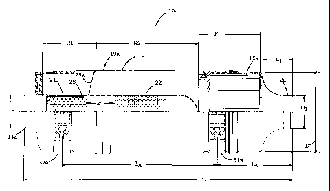
Figures 2 and 3 illustrate a filter assembly 10a for use in a fuel cell
operated passenger bus using a stack of PEM fuel cells providing an overall
power
output of 200 kW. It should be understood that filter assembly 10a is
specifically
designed for such an application, i.e., a bus running on 200 kW, and that
filter
assemblies for other applications, such as, for example, other vehicles,
stationary
units, or portable electronic application, would be designed for those
applications that
are different in size, shape and configuration, and operating parameters
without
departing from the overall features of filter assembly 10a.
The filter assembly view of Figure 2 is illustrated as rotated about its
central longitudinal axis, with respect to the illustration of Figure 3, by
180 degrees.
Filter assembly 10a includes a generally cylindrical housing l la which
defines an air
inlet 12a and an air outlet 14a. Dirty air 50 enters filter assembly 10a via
inlet 12a,
and clean air 54 exits via outlet 14a. The exterior of housing 11 a may
include
mounting brackets 31a, 32a for positioning and securing filter assembly 10a in
relation to surrounding equipment and structures. A sensor receptor port 35a
is
present on the exterior of housing 11 a adj acent outlet 14a. Filter housing
11 a may
assume any number of physical shapes other that cylindrical; for example,
filter
assembly 10a may have a cross-sectional shape that is oval or obround, square,
rectangular, or any other closed shape.
Housing l la can be made from any material that can be formed with
the desired elements, e.g., inlet I2a, outlet 14a, etc. Examples of usable
materials for
housing 11 a include metals or plastics or other polymeric materials.
Typically,
housing 11 a will be a thermoplastic or thermoset polymeric material, such as
epoxy,
polycarbonate, polyethylene, and the like. These materials may include
reinforcement, such as a scrim or fibers, within the polymeric material to
strength
housing 11a. In some embodiments it may be desired to avoid silicone mold
release
when making housing 11a or any other part or element of filter element 10a, as
silicone fumes may be detrimental to the fuel cell. Alternately, it may be
possible to
12
CA 02441087 2003-09-12
WO 02/084099 PCT/US02/11443
wash or otherwise cleanse housing 11 a to remove any contaminants such as mold
release.
Returning to the features of housing 11 a, receptor port 35 is configured
to cooperatively receive a sensor that can monitor parameters, as desired,
within the
housing internal cavity. One example of a sensor that may be desired for use
within
sensor receptor port 35a is an air mass flow sensor, generally referred to as
a flow
sensor or a flow meter. An air mass flow sensor can be used to monitor the
mass of
air passing through outlet 14a. The air mass passing through outlet 14a is
directly
related to the air mass passing through the entire system, including filter
assembly 10a
and equipment 101 of Figure 1 (such as compressor 102, fuel cell 104, and
optional
exhaust apparatus 103). By monitoring any changes, specifically decreases, in
air
mass flow passing through filter assembly 10a, the life of any physical or
particulate
filter within filter assembly 10a or any other equipment in the system can be
estimated. Alternately, a sensor can be used to monitor the level or
accumulation of
chemical contaminants that are passing through outlet 14a. By monitoring the
amount
of chemical contaminants passing through outlet 14a, the remaining life of any
chemical filter within filter assembly I Oa can be estimated.
One example of a preferred air mass flow sensor is a "hot wire" sensor,
which uses the change in resistance through a wire to determine the amount of
air
passing over the wire. Such a hot wire sensor is available, for example, from
TSI of
St. Paul, MN. Examples of devices that can monitor the accumulation or total
contaminants include those disclosed in U.S. Patent Nos. 5,976,467 and
6,187,596,
both to Dallas et al.
The various portions of filter assembly 10a are illustrated in Figure 3,
where a cut-away view of filter assembly 10a is provided. Operatively
positioned
within housing 11 a are a filter element 15a and a noise suppression element
19a.
Suppression element 19a is configured to attenuate sound waves
passing through the internal cavity defined by housing l la. In the preferred
embodiment suppression element 19a comprises a first resonator 21 and a second
resonator 22. In the preferred embodiment of the invention herein described,
first
resonator 21 is configured to attenuate sound at a peak frequency of about 900
Hz,
13
CA 02441087 2003-09-12
WO 02/084099 PCT/US02/11443
and second resonator 22 is configured to attenuate sound at a peak frequency
of about
550 Hz. Detailed information regarding sound suppression element 19 (Figure
1),
suppression element 19a, and resonators 21, 22 hereinafter described in more
detail.
Specific characteristics of a preferred configuration of the filter
assembly 10a are illustrated in Figure 4. Filter assembly 10a, specifically
housing
l la, has a length "L" no greater than about 1500 mm, preferably no greater
than about
1000 mm. In one preferred embodiment, length "L" is no greater than 32 inches
(813
mm) long. Filter assembly 10a, which is generally cylindrical, has a diameter
"D" no
greater than about 18 inches (460 mm), preferably no greater than about 16
inches
(406 mm). In the preferred embodiment, diameter "D" is no greater than 10
inches
(254 mm). Length "L" and diameter "D" are generally dependent on the amount of
volume allocated for occupation by filter assembly 10a within the system with
which
the filter assembly will be used. Such system requirements may be dictated by
the
space requirements of the application with which the system will be employed.
Air flows into filter assembly 10a via inlet 12a, which has a diameter
"DI" of about 1 to 8 inches (25 to 203 mm). In the preferred embodiment, inlet
diameter "DI" is about 4 inches (102 mrn). The length of inlet 12a "LI",
measured as
the distance from the inlet end of housing 11 a to approximately the dirty air
side of
filter element 15a, is generally about 1 to 8 inches (25 to 203 mm). In the
preferred
embodiment, "LI" is about 3.5 inches (90 rmn). Outlet 14a has a diameter "Do"
of
about 1 to 8 inches (25 to 203 mm). In the preferred embodiment, outlet
diameter
"Do" is about 4 inches (102 mm).
Filter element 15a occupies a volume within housing l la having a
length "F" of about 4 to 8 inches (102 to 203 mm). The specific length "F"
occupied
by filter element 15a will be conditioned on features such as the type of
filter element
used, its filtering capabilities, the volume of housing 11 a allotted to
suppression
element 19a (Figure 3), and the overall length "L" of housing 11 a. In the
preferred
embodiment, length "F" is about 7.3 inches (185 mm). Typically, the filter
element
15a occupies the majority of the diameter D where filter element 15a is
positioned.
Noise suppression element 19a occupies the majority of the remaining
length of housing 11 a. In the embodiment shown in Figures 3 and 4,
suppression
14
CA 02441087 2003-09-12
WO 02/084099 PCT/US02/11443
element 19a comprises a first resonator 21 and a second resonator 22. First
resonator
21 occupies a length "R," of about 6.4 inches (163 mm) and second resonator 22
occupies a length "R2" of about 12.2 inches (310 mm). The number of resonators
used and the specific lengths (e.g., Ri and RZ) occupied by the resonators are
a
function of the desired sound attenuating properties of the resonator. That
is, the
frequency of the sound attenuated by the resonators is dependent on the
configuration
of the resonators, specifically, the volume occupied. As stated, additional
information
regarding sound attenuation and resonators is provided below.
Mounting brackets 31 a, 32a on the exterior of filter assembly 10a are
spaced apart 18.5 inches (470 mm), which is designated by "LB". First mounting
bracket 31a is spaced 8.9 inches (227 mm) from inlet 12a, designated by "LA".
It is
understood that the positioning of any mounting brackets is dependant on the
overall
length "L" of filter assembly 10a, its desired positioning in respect to
surrounding
equipment or structures, and positioning of internal baffles or other
structure within
housing 11 a.
Physical or Particulate Removal Portion of the Filter Assembly
Filter assembly 10 of the present invention, in particular filter element
15, includes a portion for removing physical contaminants such as particulates
from
the incoming air 50. It is understood that large items, such as leaves, birds,
rodents
and other debris, will be removed by a screen, mesh, separator or the like
from
incoming atmospheric air 50 prior to the air reaching filter assembly 10. A
water or
liquid separator may be included to remove water or fluid from air 50 prior to
entering
filter assembly 10 as is known in the art.
A series of particulate removal portions may be used within filter
assembly 10, with each subsequent particulate removal portion removing a
smaller
sized particle. Alternately, a single particulate removal portion can be used.
Typically, the particulate removal portion contains a filter media, such
as a fibrous mat or web, including cellulosic materials, to remove particles.
Examples
of particulates or particles removed by a particulate removal portion include
dust, dirt,
pollen, diesel particulate, insects, -wood chips and sawdust, metal shavings,
cosmic
CA 02441087 2003-09-12
WO 02/084099 PCT/US02/11443
dust, and the like. Some particulates may be doubly harmful to the operation
of the
fuel cell, both as the physical particle and the molecular structure of the
particle; for
example, limestone, is a basic material that could harm the electrolyte in a
PEM fuel
cell, which is acidic. Other types of fuel cells may be detrimentally affected
by acidic
contaminants. Heavy hydrocarbons, particularly those found in road tar, can
also
detrimentally affect operation of a fuel cell.
The filter media can be treated in any number of ways to improve its
efficiency in removing minute particulates; for example, electrostatically
treated
media can be used, as can cellulose or synthetic media or a combination
thereof,
having one or more layers of nanofiber, or other types of media known to those
skilled
in the art. For details regarding types of nanofiber that could be used, see
for
example, U.S. Patent No. 4,650,506 (Barris et al.).
It is understood that any number of particulate removal portions having
any combination of particulate removal efficiency can be used. The desired
particulate removal system will depend on the type, size and nature of
contaminants
present in the atmosphere (for example, leaves, cottonwood blossoms, lint,
snow,
cosmic dust, etc.) and the desired cleanliness level of the resulting filtered
air. The
media used in filter element 15 can vary, depending on the particulate removal
efficiency desired, the maximum level of acceptable pressure drop through
filter
element 15, and other such factors.
Filter element 15a of Figures 3 and 4 is illustrated in more detail in
Figure 5. W the preferred embodiment, filter element 15a includes filter media
55 that
is wound about a central axis to form a cylindrically shaped filter element.
The filter
element includes a sealing system generally indicated at 60. One preferred
sealing
system is disclosed, for example, in U.S. Patent No. 4,720,292.
In preferred constructions, filter media 55 is designed to remove
particulate from air passing through the filter media 55, while the sealing
system 60 is
designed to provide a seal between filter element 15a and the interior
sidewalls of
housing 11 a, as shown in Figures 3 and 4. By the term "seal," it is meant
that sealing
system 60, under normal conditions, prevents unintended levels of air from
passing
through a region between the outer surface of filter element 15a and the
interior sidewall
16
CA 02441087 2003-09-12
WO 02/084099 PCT/US02/11443
of housing 11 a; that is, sealing system 60 inhibits air flow from avoiding
passage
through filtering media 55 of filter element 15a.
In certain preferred arrangements, filter media 55 is configured for
straight-through flow. By "straight-through flow," it is meant that filter
media 55 is
configured so as to have a first flow face 105 (corresponding to an inlet end,
in the
illustrated embodiment) and an opposite, second flow face 110 (corresponding
to an
outlet end, in the illustrated embodiment). Straight-through flow is often
desired
because a straight-through flow filter can handle greater amounts of air
passing
therethrough compared to, for example, a pleated filter. It is intended that
there is no
distinction between "straight-though flow" and "in-line flow". Air enters in
one
direction 114 through first flow face 105 and exits in the same direction 116
from
second flow face 110. In this embodiment, first flow face 105 correlates to
dirty air side
13 of the filter element of Figure 1 and second flow face 110 correlates to
clean air
side 17 of the filter element of Figure 1.
When filter element 15a is used with an in-line flow housing such as
housing 11 a of Figures 3 and 4, in general, the air will enter through inlet
12a of housing
11 a in one direction, enter filter element 15a through first flow face 105 in
the same
direction, exit filter element 15a in the same direction from second flow face
110, and
exit housing 1 la through outlet 14a also in the same direction.
Although first flow face 105 is described above as corresponding to an
inlet end (and dirty air side 13), and second flow face 110 is described above
as
corresponding to an outlet end (and clean air side 17), the inlet and outlet
ends (and dirty
air side and clean air side) can be reversed. That is, first flow face 105
depicted in
Figure 5 can correspond to an outlet end, while second flow face 110 depicted
in Figure
5 can correspond to an inlet end. In other words, the physical orientation of
filter
element 15a relative to the direction of air flow therethrough could be
reversed.
In Figure 5, first flow face 105 and second flow face 110 are depicted as
planar and as parallel to one another. In other embodiments, first flow face
105 and
second flow face 110 can be non-planar, for example, frusto-conical. Further,
first flow
face 105 and second flow face 110 need not be parallel to each other.
17
CA 02441087 2003-09-12
WO 02/084099 PCT/US02/11443
In the preferred embodiment, the media of filter element 15a is a wound
or rolled construction. That is, filter element 15a will typically include a
layer of filter
media that is wound completely or repeatedly about a central axis. Typically,
the wound
construction will be a coil, in that a layer of filter media will be rolled in
a series of turns
around a central axis. In arrangements where a wound, coiled~construction is
used, filter
element 15a will be in the shape of a roll of filter media, typically
permeable fluted filter
media.
Attention is now directed to Figure 6, where a schematic, perspective
view demonstrating the principles of operation of certain preferred media
usable in the
filter constructions herein is illustrated. In Figure 6, a fluted media
construction is
generally designated at 122. Preferably, fluted construction 122 includes a
layer 123 of
corrugations having a plurality of flutes 124 and a face sheet 132. The Figure
6
embodiment shows two sections of face sheet 132, at 132A (depicted on top of
corrugated layer 123) and at 132B (depicted below corrugated layer 123).
Typically, the
preferred media construction 125 used in arrangements described herein will
include
corrugated layer 123 secured to bottom face sheet 132B. When using this media
construction 125 in a rolled construction, it typically will be wound around
itself, such
that bottom face sheet 132B will cover the top of corrugated layer 123. Face
sheet 132
covering the top of corrugated layer 123 is depicted as 132A. It should be
understood
that in a "rolled" media configuration face sheet 132A and 132B are the same
sheet 132.
When using this type of media construction 125, flute chambers 124
preferably form alternating peaks 126 and troughs 128. Peaks 126 and troughs
128
divide flutes 124 into an upper row and lower row. In the particular
configuration
shown in Figure 6, the upper flutes form flute chambers 136 closed at the
downstream
end, while flute chambers 134 having their upstream end closed form the lower
row of
flutes. Fluted chambers 134 are closed by a first end bead 138 that fills a
portion of the
upstream end of the flute between fluting sheet 130 and second facing sheet
132B.
Similarly, a second end bead 140 closes the downstream end of alternating
flutes 136.
In some preferred systems, both first end bead.138 and second end bead I40 are
straight
along all portions of the media construction 125, never deviating from a
straight path.
In some preferred systems, first end bead 138 is both straight and never
deviates from a
18
CA 02441087 2003-09-12
WO 02/084099 PCT/US02/11443
position at or near one of the ends of media construction 125, while second
end bead
140 is both straight and never deviates from a position at or near one of the
ends of
media construction 125. Flutes 124, face sheet 132, and end beads 138, 140
provide
media construction 125 that can be formed into filter element 15a.
When using media constructed in the form of media construction 125,
during use, unfiltered air enters flute chambers 136 as indicated by the
shaded arrows
144. Flute chambers 136 have their upstream ends 146 open. The unfiltered
fluid flow
is not permitted to pass through downstream ends 148 of flute chambers 136
because
their downstream ends 148 are closed by second end bead 140. Therefore, the
air is
forced to proceed through fluting sheet 130 or face sheets 132. As the
unfiltered air
passes through fluting sheet 130 or face sheets 132, the air is cleaned or
filtered. The
cleaned air is indicated by the unshaded arrow 150. The air then passes
through flute
chambers 134 (which have their upstream ends 151 closed) to flow through the
open
downstream end 152 (Figure 5) out fluted construction 122. With the
configuration
shown, the unfiltered air can flow through fluted sheet 130, upper facing
sheet 132A, or
lower facing sheet 132B, and into a flute chamber 134.
Typically, media construction 125 will be prepared and then wound to
form a rolled construction 100 of filter media. When this type of media is
selected for
use, media construction 125 includes corrugated layer 123 secured with end
bead 138 to
bottom face sheet 132B (as shown in Figure 6, but without top face sheet
132A). In
these types of arrangements, media construction 125 will include a leadiizg
edge at one
end and a trailing edge at the opposite end, with a top lateral edge and a
bottom lateral
edge extending between the leading and trailing edges. By the teen "leading
edge", it is
meant the edge that will be initially turned or rolled, such that it is at or
adjacent to the
center or core of the rolled construction. The "trailing edge" will be the
edge on the
outside of the rolled construction, upon completion of the turning or coiling
process.
The leading edge and the trailing edge should be sealed between
corrugated sheet 123 and bottom face sheet 132B, before winding the sheet into
a coil,
in these types of media constructions 125. While a number of ways are
possible, in
certain methods, the seal at the leading edge is formed as follows: (a)
corrugated sheet
123 and bottom face sheet 132B are cut or sliced along a line or path
extending from the
19
CA 02441087 2003-09-12
WO 02/084099 PCT/US02/11443
top lateral edge to the bottom lateral edge (or, from the bottom lateral edge
to the top
lateral edge) along a flute 124 forming a peak 126 at the highest point (or
apex) of peak
126; and (b) sealant is applied between bottom face sheet 132B and corrugated
sheet
123 along the line or path of cut. The seal at the trailing edge can be formed
analogously to the process of forming the seal at the leading edge. While a
number of
different types of sealant may be used for forming these seals, one usable
material is a
non-foamed sealant available from H.B. Fuller, St. Paul, Minnesota.
When using media construction 125, it may be desired by the system
designer to wind the construction 125 into a rolled construction of filter
media, such as
filter element 15a of Figure 5. A variety of techniques can be used to coil or
roll the
media. It can be appreciated that non-round center winding members may be
utilized
for making other filtering media shapes, such as filter media having an oblong
or
obround, oval, rectangular, or racetrack-shaped profile.
Media construction 125 can also be wound without a mandrel or center
core. One method of forming a coreless rolled construction is as follows: (a)
troughs
128 of the first few corrugations of corrugated sheet 123 spaced from the
leading edge
are scored from the top lateral edge to the bottom lateral edge (or from the
bottom lateral
edge to the top lateral edge) to help in rolling construction 125; for
example, the first
four corrugations from the leading edge will have a score line cut along
troughs 128; (b)
bead 140 of sealant is applied along the top of corrugated sheet 123 along the
lateral
edge opposite from the lateral edge having end bead 138; (c) the leading edge
is initially
turned or rolled over against itself and then pinched together to be sealed
with sealant
bead 140; and (d) the remaining corrugated sheet 123 having bottom face sheet
132B
secured thereto is coiled or rolled or turned around the pinched leading edge.
~ In other methods, coreless constructions can be made from media
construction 125 by automated processes, as described in U.S. Patent Nos.
5,543,007
and 5,435,870. In still other methods, the media construction can be rolled by
hand.
When using rolled constructions such as filter construction 100, the
system designer will want to ensure that the outside periphery of construction
100 is
closed or locked in place to prevent filter construction 100 from unwinding.
There are a
variety of ways to accbmplish this. In some applications, the outside
periphery is
CA 02441087 2003-09-12
WO 02/084099 PCT/US02/11443
wrapped with a periphery layer. The periphery layer can be a non-porous,
adhesive
material, such as plastic with an adhesive on one side. When this type of
layer is
utilized, the periphery layer prevents filter construction 100 from unwinding
and
prevents air from passing through the outside periphery of filter construction
100,
maintaining straight-through flow through filter construction 100.
In some applications, filter construction 100 is secured in its rolled
construction by sealing the trailing edge of media construction 125 with an
adhesive or
sealant along a line 160 (Figure 5) to secure the trailing edge to the outside
surface of
filter construction 100. For example, a bead of hot-melt may be applied along
line 160.
Additionally or alternatively, a support band 162 can be provided
around the outer perimeter of filter construction 100 to secure the trailing
edge. In
Figure 5, support band 162 is shown positioned at first flow face 105.
Filter element 15a includes an end frame 200 positioned at second flow
face 110. A cross-sectional fragmented view of filter element 15a is shown in
Figure
7; filter construction 100, with its various features, is shown in phantom.
Referring to
both Figures 5 and 7, frame 200 includes an outer annular peripheral band 205
and
radial cross-braces 210. Cross-braces 210 extend inwardly from the outer
peripheral
band or collar 205 and meet at center 215 on the axis of the filter element.
The
crossbraces define an annular recessed seat portion when they meet at the
center 215
of the frame 200. Peripheral band 205 extends along the outer perimeter of
filter
construction 100 at second flow face 110 and extends longitudinally distally
away
from second flow face 110. In the particular embodiment shown in Figures 5 and
7,
frame 200 includes a second inner annular ring 212 that intersects and
connects to the
cross-braces 210.
End frame 200 supports sealing system 60 and provides a solid,
relatively non-deformable surface to facilitate the seal between the filter
element and
filter housing formed by sealing system 60. In particular, sealing system 60
comprises an annular ring of round sealant material that is mounted to and
seated on
the distal portion of peripheral band 205 that projects outwardly from second
flow
face 110. Sealing system 60 is preferably a compressible material, such as a
polyurethane foam material, that is configured to cooperatively engage the
interior
21
CA 02441087 2003-09-12
WO 02/084099 PCT/US02/11443
sidewalls of housing 11 a and provide an air-tight seal. Sealing system 60 can
have a
stepped cross-sectional configuration of decreasing outermost diameter
dimensions to
facilitate sealing and to ensure a tight seal.
In general, for a properly functioning radially sealing structure, the
compressible sealing system 60 needs to be compressed when filter element 15a
is
operatively mounted in housing l la. W many preferred constructions, it is
compressed about 15% to 40% (often about 20 to 33%) of its thickness, at the
thickest
portion thereof, to provide for a strong robust seal yet still be one that can
result from
hand installation of the element with forces on the order of 80 pounds or
less,
preferably 50 pounds or less, and generally from about 20-40 pounds.
A second embodiment of a filter element for use in the filter assembly
of the present invention is illustrated in Figure 8 as filter element 15b.
Filter element
15b is similar to filter element 15a of Figures 5 .and 7, except that frame
200 of filter
element 15b does not include inner annular ring 212.
Additional details regarding filter element 15a, filter element 15b,~and
other usable filter elements can be found in U.S. Patent No. 6,190,432.
It is understood that other filter constructions, other than those having
straight-through flow, can be used. Examples of other particulate filter
constructions
that can be used include pleated media filters, panel filters, filters having
a volume of
depth media, and the like.
A Chemical Removal Portion of the Filter Assemb
Referring again to Figure l, filter assembly 10 preferably also includes
a portion designed to remove contaminants from the atmosphere by either
adsorption
or absorption. As used herein, the terms "adsorb", "adsorption", "adsorbent"
and the
like, are intended to also include the mechanisms of absorption and
adsorption.
The chemical removal portion typically includes a physisorbent or
chemisorbent material, such as, for example, desiccants (i.e., materials that
adsorb or
absorb water or water vapor) or materials that adsorb or absorb volatile
organic
compounds and/or acid gases and/or basic gases. The terms "adsorbent
material,"
'°adsorption material," "adsorptive material," "absorbent material,"
absorption
22
CA 02441087 2003-09-12
WO 02/084099 PCT/US02/11443
material," absorptive material," and any variations thereof, are intended to
cover any
material that removes chemical contaminants by adsorption or absorption.
Suitable
adsorbent materials include, for example, activated carbon, activated carbon
fibers,
impregnated carbon, activated alumina, molecular sieves, ion-exchange resins,
ion-
s exchange fibers, silica gel, alumina, and silica. Any of these materials can
be
combined with, coated with, or impregnated with materials such as, for
example,
potassium permanganate, calcium carbonate, potassium carbonate, sodium
carbonate,
calcium sulfate, citric acid, phosphoric acid, other acidic materials, or
mixtures
thereof. In some embodiments, the adsorbent material can be combined or
impregnated with a second material.
The adsorbent material typically includes particulates or granulated
material and can be present in varied configurations, for example, as
granules, beads,
fibers, fine powders, nanostructures, nanotubes, aerogels, or can be present
as a
coating on a base material such as a ceramic bead, monolithic structures,
paper media,
or metallic surface. Typically, the adsorbent materials, especially
particulate or
granulated materials, are provided as a bed of material.
Alternately, the adsorbent material can be shaped into a monolithic or
unitary form, such as, for example, a large tablet, granule, bead, or
pleatable or
honeycomb structure that optionally can be further shaped. In at least some
instances,
the shaped adsorbent material substantially retains its shape during the
normal or
expected lifetime of the filter assembly. The shaped adsorbent material can be
formed
from a free-flowing particulate material combined with a solid or liquid
binder that is
then shaped into a non-free-flowing axticle. The shaped adsorbent material can
be
formed by, for example, a molding, a compression molding, or an extrusion
process.
Shaped adsorbent articles are taught, for example, in U.S. Patent Nos.
5,189,092
(Koslow), and 5,331,037 (Koslow).
The binder used for providing shaped articles can be dry, that is, in
powdered and/or granular form, or the binder can be a liquid, solvated, or
dispersed
binder. Certain binders, such as moisture curable urethanes and materials
typically
referred to as "hot melts", can be applied directly to the adsorbent material
by, for
example, a spray process. In some embodiments, a temporary liquid binder,
including
23
CA 02441087 2003-09-12
WO 02/084099 PCT/US02/11443
a solvent or dispersant which can be removed during the molding process, is
used.
Suitable binders include, for example, latex, microcrystalline cellulose,
polyvinyl
alcohol, ethylene-vinyl acetate, starch, carboxyl methyl cellulose,
polyvinylpyrrolidone, dicalcium phosphate dihydrate, and sodium silicate.
Preferably
the composition of a shaped material includes at least about 70%, by weight,
and
typically not more than about 98%, by weight, adsorbent material. In some
instances,
the shaped adsorbent includes 85 to 95%, preferably, approximately,90%, by
weight,
adsorbent material. The shaped adsorbent typically includes not less than
about 2%,
by weight, binder and not more than about 30%, by weight, binder.
Another embodiment of a suitable adsorbent material for use in the
chemical removal portion is an adsorbent material that includes a carrier. For
example, a mesh or scrim can be used to hold the adsorbent material and
binder.
Polyester and other suitable materials can be used as the mesh or scrim.
Typically,
any carrier is not more than about 50% of the weight of the adsorbent
material, and is
more often about 20 to 40% of the total adsorbent weight. The amou~it of
binder in
the shaped adsorbed article with the Garner typically ranges about 10 to 50%
of the
total adsorbent weight and the amount of adsorbent material typically ranges
about 20
to 60% of the total adsorbent weight.
The chemical removal portion can include strongly basic materials for
the removal of acid contaminants from the air, or strongly acidic materials
for the
removal of basic contaminants from the air, or both. Preferably, the basic
materials
and acidic materials are sufficiently separated from each other so that they
do not
interact with or cancel each other. In some embodiments, the adsorbent
material itself
may be the strongly acidic or strong basic material. Examples of such
materials
include materials such as polymer particulates, activated carbon media,
zeolites, clays,
silica gels, and metal oxides. In other embodiments, the strongly acidic
materials and
the strongly basic materials can be provided as surface coatings on carriers
such as
granular particulate, beads, fibers, cellulosic material, fine powders,
nanotubes, and
aerogels. Alternately or additionally, the acidic and basic material that
forms the
acidic and basic surfaces may be present throughout at least a portion of the
carrier;
24
CA 02441087 2003-09-12
WO 02/084099 PCT/US02/11443
this can be done, for example, by coating or impregnating the carrier material
with the
acidic or basic material.
Examples of acidic compounds that are often present in atmospheric air
and are considered as contaminants for fuel cells include, for example, sulfur
oxides,
nitrogen oxides, hydrogen sulfide, hydrogen chloride, and volatile organic
acids and
nonvolatile organic acids. Examples of basic compounds that are often present
in
atmospheric air and are considered as contaminants for fuel cells include, for
example,
ammonia, amines, amides, sodium hydroxides, lithium hydroxides, potassium
hydroxides, volatile organic bases and nonvolatile organic bases.
For PEM fuel cells, the cathodic reaction occurs under acidic
conditions, thus, it is undesirable to have basic contaminants present. An
example of
a preferred material for removing basic contaminants, such as ammonia, is
activated
carbon impregnated or coated with citric acid.
A first embodiment of a filter element 15 (Figure 1) having both the
physical or particulate removal portion and a chemical removal portion is
shown in
Figure 9 as filter element 15c. Filter element 15c is similar to filter
element 15a of
Figure 7 in that filter element 15c has filter construction 100 (shown in
phantom in
Figure 9) with first flow face 105 and second flow face 110, support band 162,
frame
200, and sealing system 60. Filter element 15c further includes an adsorbent
element
300, such as shaped activated carbon. Adsorbent element 300 is positioned on
frame
200 within frame 200 and sealing system 60. The compressible sealing system 60
frictionally retains adsorbent element 300 in the desired position, but can be
deformed
to release adsorbent element 300 for replacement when the adsorbent is spent.
In a preferred embodiment, adsorbent element 300 is a shaped mass of
activated carbon material held together by a thermoplastic binder. A preferred
adsorbent element 300 includes activated carbon material, sieve size 12x20 or
8x16,
molded with a level of 8% ethylene-vinyl acetate binder. Such a preferred
adsorbent
element 300 can be made in accordance with the teachings of U.S. Patent Nos.
5,189,092 (Koslow) or 5,331,037 (Koslow). In another preferred embodiment,
adsorbent element 300 is made from layers (not shown) of carbon material
available
from Hollingsworth & Vose of East Walpole, MA (also known as H&V).
CA 02441087 2003-09-12
WO 02/084099 PCT/US02/11443
In the embodiment shown, adsorbent element 300 is positioned
adjacent second flow face 110; thus air flowing through filter element 15c
would enter
filter construction 100 via first flow face 105 and exit via second flow face
110, and
then pass through adsorbent element 300. Such a configuration has adsorbent
element
300 "downstream" of the particulate removing filter construction 100. All air
passing
through filter construction 100 preferably passes through adsorbent element
300. It is
understood that adsorbent element 300 could alternatively be positioned
"upstream"
from filter construction 100.
A second embodiment of a filter element 15 (Figure 1) having both the
physical or particulate removal portion and a chemical removal portion is
shown in
Figure 10 as filter element 15d. Filter element 15d is similar to filter
element 15a in
that filter element 15d has filter construction 100 (shown in phantom) with
first flow
face 105 and second flow face 110, support band 162, frame 200, and sealing
system
60. Filter element 15d further includes the adsorbent element 300, except that
adsorbent element 300 is positioned between second flow face 110 and cross-
braces
210 of frame 200. Peripheral band 205 (see Figure 8) of frame 200 holds
absorbent
300 against second flow face 110. Adsorbent element 300 may be permanently
affixed to one or each of frame 200 and filter construction X00, or may be
disengageable therefrom. Again, all air passing through second flow face 110
of filter
construction 100 preferably also passes through adsorbent element 300.
In filter elements 15c and 15d, the chemical removal portion,
specifically adsorbent element 300, has been combined with the particulate
removal
portion to form a single structure. It is understood that in some embodiments,
the
chemical removal portion will be separate and spaced from the particulate
removal
portion. It is further understood that the particulate removal portion and
chemical
removal portion can be combined in a single element that removes both physical
and
chemical contaminants. In one example, the filter media of a particulate
removal
portion can be made with fibers that have a surface treatment capable of
chemisorbing
or otherwise reacting or interacting with acidic or basic contaminants, thus
providing
a chemical removal portion. In another example, a bed of activated carbon
granules
26
CA 02441087 2003-09-12
WO 02/084099 PCT/US02/11443
can be arranged and configured to remove physical contaminants from the air if
the
spacing between the granules is sufficiently small.
One preferred filter element that includes both particulate and chemical
removal portions is disclosed in U.S. Patent No. 6,152,996 (Linnersten et
al.).
Additional information regarding chemical removal portions of filter
elements for use with fuel cell systems is disclosed in U.S. patent
application Serial
No. 09/660,127; filed September 12, 2000.
A Sound Suppression Element of the Filter Assembly
Referring again to Figure 1, filter assembly 10 of the present invention
includes a noise or sound suppression element 19 to reduce or suppress the
level of
noise or sound emanating from equipment 101. Such noise reduction is
preferably at
least 3 dB at one meter, typically at least 6 dB, preferably at least 10 dB,
and most
preferably at least 25 dB. The catalytic reaction occurring within fuel cell
102 is a
silent process, in that the hydrogen fuel, the reaction at the cathode, and
the
production of power, produce no sound audible by humans. Details regarding the
construction and operation of fuel cells 102 are provided below. However,
although
fuel cell 102 is silent, the equipment or machinery often used to provide an
increased
flow of air to fuel cell 102, such as compressor 104 of Figure 1, generally
produce
significant noise. Air moving equipment that may be used in conjunction with
fuel
cell 102 includes compressors, fans, blowers, and pumps.
Sound emanating from equipment such as compressor 104 will travel
in any direction as permitted by the fuel cell, equipment and filter
assemblies. That is,
sound would travel upstream from the compressor, against the flow of the air,
to filter
assembly 10; and sound would travel downstream to fuel cell 102. In accordance
with
the present invention, filter assembly 10 reduces the noise emanating from
compressor
104 through the filter assembly and out to the surrounding environment, by
attenuating the sound with sound suppression element 19 of filter assembly 10.
Sound suppression element 19 can be any type of element that,
together with other features of filter assembly 10 that may attenuate or
otherwise
reduce the sound, provides reduction in the sound by at least 3 dB, typically
at least 6
27
CA 02441087 2003-09-12
WO 02/084099 PCT/US02/11443
dB, preferably by at least 10 dB, and more preferably by at least 25 dB.
Examples of
sound suppression elements 19 include mufflers, lined ducts, baffles, bends in
the
sound path, plenums, expansion chambers, resonators, sonic chokes, full
chokes,
sound adsorptive material, and various combinations thereof. Various details
regarding sound suppression elements are disclosed, for example, in U.S.
Patent No.
6,082,487 (Angelo et al.).
Certain typical suppression elements 19 include an outer wall, usually
cylindrical, defining an internal volume, and an inlet and outlet tube
oriented within
the internal volume of the outer wall. It is preferred that the outer wall and
any other
structures have minimal surfaces that are planar or flat; rather, it is
preferred that the
surfaces of suppression element 19 are curved, to reduce the amount of
vibration or
drumming that often occurs with flat walls. In typical arrangements, the
outlet tube
defines a sonic choke. An inner, perforated wall is spaced from the outer
wall, to
define an annular volume therebetween. The annular volume may include a
packing
or padding of absorptive material within the annular volume. This absorptive
material
within the annular volume provides an absorptive function, and also helps
reduce
drumming of the outer wall or shell. In certain arrangements, the inner
perforated
wall and annular volume are in alignment with the iWet region of suppression
element
19. That is, the inner perforated wall may circumscribe at least a portion of
the inlet
tube.
A preferred suppression element 19 is a resonator. A resonator is an
enclosed volume of air in communication with the exterior through a small
opening.
The enclosed air resonates at a finite range of frequency. This range of
frequency and
the level of attenuation depend on the dimensions of the enclosed volume. The
frequency resonated within the enclosed volume determines the noise frequency
attenuated by the resonator.
In filter assembly 10a illustrated in Figures 3 and 4, suppression
element 19a comprises first resonator 21 and second resonator 22. Notice that
first
resonator 21 is positioned adjacent outlet 14a and second resonator 22 is
positioned
upstream or closer to inlet 12a. Such designated "first" and "second"
positioning of
the resonators has been selected because noise from equipment 101 (Figure 1)
would
28
CA 02441087 2003-09-12
WO 02/084099 PCT/US02/11443
be moving upstream (opposite to the direction of air flow) through filter
assembly 10a
from outlet 14a to inlet 12a. First and second resonators 21, 22 can be
designed to
attenuate the same or a different range of sound frequencies. Generally, if
resonators
21, 22 remove the same range of noise frequency, the level of noise decrease
will be
greater. If resonators 21, 22 remove noise of different frequency ranges, the
overall
ranges of frequencies attenuated will be greater.
In one preferred embodiment, first resonator 21 is designed to attenuate
sound at a peals frequency of about 900 Hz, and second resonator 22 is
designed to
attenuate sound waves at a peak frequency of about 550 Hz. As illustrated in
Figures
3 and 4, various features differ between first resonator 21 and second
resonator 22.
For example, the volume occupied by second resonator 22 is much greater that
that
occupied by first resonator 21. The volume of first resonator 21 is generally
defined
by the interior walls of housing 11 a between outlet 14a and an internal
annular baffle
25a. The volume occupied by second resonator 22 is generally defined by the
interior
walls of housing 11 a between internal baffle 25a and flow face 110 (Figure 5)
of the
filter element. Additionally, the perforations within a central wall structure
28 vary
between first resonator 21 and second resonator 22. For example the shape and
size
of the apertures, the spacing between adjacent apertures, and their
orientation differ
between the two resonators. These various features of each resonator dictate
the
frequencies attenuated thereby. Design of resonators for desired frequency
attenuation is well known in the art of sound suppression and attenuation and
will not
be detailed herein.
Additionally, first and second resonators 21, 22 are spaced
approximately 3 inches (76 mm) apart, as measured by the longitudinal spacing
between the perforations in central wall structure 28 of the two resonators.
This
distance between resonators 21, 22, designated at 24 in Figure 4, will
attenuate sound
having a frequency whose 1/4 wavelength is equal to this distance. A distance
of
approximately 3 inches (76 mm) provides a peak attenuation of about 1100 Hz.
Figure 11 graphically illustrates the levels and frequencies of sound
attenuated by the preferred embodiment described above. First resonator 21
. attenuates sound at a peak frequency of about 900 Hz, second resonator 22
attenuates
29
CA 02441087 2003-09-12
WO 02/084099 PCT/US02/11443
sound at a peak frequency of about 550 Hz, and the 1l4 wavelength spacing 24
attenuates sound at about 1100 Hz. The composite sound attenuation of the
three
spans the fundamental frequencies of a typically twin-screw compressor, such
as the
160 1100 Hz of a Lysholm twin screw compressor manufactured by Opcon.
Referring again to Figure 1, suppression element 19 may be positioned
within housing 11, and in some embodiments, suppression element 19 is defined
by
housing 11. In the embodiment of filter assembly 10a, first and second
resonators 21,
22 are partially defined by housing 11 a. The interior walls of housing 11 a
together
with internal baffle 25, define the volume occupied by resonators 21, 22.
Various other features of housing 11 a may provide sound attenuation.
For example, inlet 12a, as illustrated in Figure 4, has a bell shaped
expansion in the
axial direction from a 4 inch (102 mm) to 10 inch (254 mm) diameter. This
expansion
provides a broadband sound attenuation of approximately 3dB.
It is noted that filter element 15, such as any of filter elements 15a,
15b, 15c, 15d, may have additional sound attenuation properties associated
with the
particulate removal portion or the chemical removal portion. For example,
filter
construction 100 (Figures 5 and 7), may attenuate some frequencies a low
amount,
such as ldB. Additionally, adsorbent element 300 (Figures 9 and 10) may
attenuate
some frequencies. It has been found that various shaped adsorbent elements,
such as
those taught by U.S. Patent Nos. 5,189,092 (Koslow), and 5,331,037 (Koslow),
provide some sound attenuation; the frequency attenuated and the level (i.e.,
dB) will
depend on the specific features of the shaped adsorbent element.
A Second Embodiment of a Filter Assembly
A second example of a filter assembly is shown in fragmented cross-
section in Figure 12 as a filter assembly 10b. Similar to filter assembly 10a,
filter
assembly l Ob is for use in a fuel cell operated passenger bus using a stack
of PEM
fuel cells providing an overall power output of 200 kW. It should be
understood that
filter assembly l Ob is specifically designed for such an application, (i.e.,
a bus running
on 200 kW), and that filter assemblies for other applications would be
designed for
CA 02441087 2003-09-12
WO 02/084099 PCT/US02/11443
those applications that are different in size, shape and configuration,
without departing
from the overall features of filter assembly l Ob.
Filter assembly l Ob includes a housing l 1b which defines an inlet 12b
and an outlet 14b. Dirty air 50 enters filter assembly l Ob via inlet 12b, and
clean air
54 exits via outlet 14b. The exterior of housing 1 1b includes mounting
brackets 31b,
32b for positioning and securing filter assembly 10b in relation to
surrounding
equipment and structures. A sensor receptor port 35b is present on the
exterior of
housing 1 1b to allow for connection of a sensor, as may be desired. Filter
element
15a is positioned within housing l 1b. In filter assembly l Ob of this
embodiment, the
filter element 15a used is the same as filter element 15a of filter assembly
10a of the
first embodiment. Also within housing l 1b is a noise suppression element
generally
illustrated at 19b.
Suppression element 19b comprises a resonator 23 configured to
attenuate sound at a peak of about 900 Hz. Detailed information regarding
resonators
is provided above with respect to the first embodiment of filter assembly 10a.
Resonator 23 has one end operatively connected in fluid communication with the
outlet port 14b of the filter assembly, and an opposite end to which is
secured an
annular mounting bracket 342. Mounting bracket 342 has a perforated central
portion
allowing air to pass therethrough into resonator 23, and defines an annular
seal seat
343 that includes a cylindrical extension flange 345 axially projecting away
from
resonator 23 in a direction toward inlet port 12b. The distal end of flange
345 is
outwardly flared, for reasons which will be described below.
Filter assembly l Ob also includes an adsorbent element 310, shown
enlarged in Figure 13. Adsorbent element 310 comprises a cylindrical mass of
carbon
330 extending between first and second ends 330a and 330b respectively. Carbon
element 330 is in the preferred embodiment a hollow, cylindrical extrusion of
activated carbon held together by a thermoplastic binder. Carbon element 330
can be
produced, for example, by the teachings of U.S. Patent Nos. 5,189,092
(Koslow), and
5,331,037 (Koslow).
In some embodiments, the filter element, such as filter element 15a,
can be combined with an adsorbent element, such as adsorbent element 310, into
a
31
CA 02441087 2003-09-12
WO 02/084099 PCT/US02/11443
single construction that provides both particulate and chemical filtration.
For
example, a particulate removal media can be positioned around the external
surface of
carbon element 330. A filter element that includes both particulate and
chemical
removal portions is disclosed in U.S. Patent No. 6,152,996 (Linnersten et
al.).
The extruded cylindrical carbon configuration 330 of adsorbent element
310 provides a solid surface for direct attachment of a sealing system 340
thereto at end
330a and an end cap 350 at end 330b. Such "solid" carbon/binder extrusion also
forms a
unified adsorbent filter element 310 that does not itself release any carbon
or other
particles or contaminants into the filtered air stream.
End cap 350 is sealingly secured to end 330b of carbon adsorbent
element 330. End cap 350 diverts air exiting filter element 15a so that the
air passes
along the outer cylindrical surface of adsorbent 330 when mounted as shown in
Figure
12 rather than moving directly, axially into the central bore region of carbon
adsorbent
element 330. Air exiting from filter element 15a impinges on a curved surface
355 of
cap 350 and is rerouted from its "straight-line" flow from filter 15a to a
flow having a
radial component. Surface 355 is an arcuately shaped surface radially
extending from
an axially aligned tip 352. Curved surface 355 smoothly diverts the air with
minimal
resistance. Tip 352 is the central point of exposed surface 355 of cap 350,
although in
some embodiments tip 352 may not be centrally positioned on cap 350. It will
be
appreciated that other surface configurations of end cap 350, such as flat or
stepped
surfaces, could be used. Referring to Figures 13 and 14, end cap 350 includes
apertures 354 for passage of air therethrough and along the outer surface of
carbon
element 330. Radial arms 356 define and separate apertures 354 and provide
structural support to cap 350. Additionally, some air may pass around the
outer
periphery of cap 350 and between cap 350 and the interior of housing 1 1b.
When adsorbent element 310 is operatively mounted as shown in
Figure 12, sealing system 340 provides an airtight seal at end 330a between
adsorbent
element 310 and seal seat 343 and flange 345 of mounting bracket 342 (Figure
12).
The flared distal end of flange 345 helps guide sealing system 340 to seal
seat 343.
The formed seal, in combination with baffle 25b and end cap 350, direct air
flow
through adsorbent element 310, and, under normal conditions, prevent
unintended
32
CA 02441087 2003-09-12
WO 02/084099 PCT/US02/11443
levels of air from passing through mounting bracket 342 and into resonator 23
before the
air has first passed through carbon element 330. With air flowing in the
direction of
from inlet 12b to outlet 14b, baffle 25b forms a seal downstream from mounting
bracket
342 and between the inner surface of the sidewalls of housing l 1b and
resonator 23.
End cap 350, baffle 25b and sealing system 340 require all air flow from
filter element
15a to pass through carbon adsorbent element 330 and through mounting bracket
342
before passing on to the filter assembly outlet 14b.
Sealing system 340 is typically made from a flexible, compressible
material, such as polyurethane. The embodiment illustrated in Figure 13 shows
sealing
system 340 having a "stepped" configuration of decreasing outermost dimension,
which
improves seating and sealing against sealing seat 343 and extension flange 345
of
mounting bracket 342. Sealing system 340 directs air flow from filter element
15a
through carbon element 330 before entering resonator 23.
In addition to managing air flow as described above, end cap 350
provides structural support and anchoring of second end 330b of absorbent
element
310 to filter element 15a by engaging with frame 200, specifically, with
center 215 of
frame 200 (see Figure 5). Tip 352 is adapted for cooperative insertion into
and
retention by the recessed portion of center 215. The fit of tip 352 within
frame 200
should hold adsorbent element 310 in axial alignment with filter element 15a,
although other features within the interior of housing 1 1b may be used to
retain
adsorbent element 310 in the desired position. Pressure in the axial direction
exerted
by frame 200 on tip 352 operatively hold adsorbent element 310 in sealing
engagement with sealing system 340 against seal seat 343.
Each of sealing system 340 and cap 350 can be temporarily or
permanently attached to carbon element 330. To provide a permanent attachment,
sealing system 340 can be attached to carbon 330, for example, by adhesive, or
by
directly molding sealing system 340 onto carbon 330. For permanent attachment
of
cap 350, cap 350 can be, for example, adhesively attached to carbon 330. Cap
350
may include an annular recess to accept a portion of second end 330b of carbon
330.
Adsorbent element 310 functions both as a chemical removal portion
and as an element of sound suppression element 19b. Adsorbent element 310 is
33
CA 02441087 2003-09-12
WO 02/084099 PCT/US02/11443
functionally similar to adsorbent element 300 of Figures 9 and 10 in that it
comprises
adsorbent material for removing chemical contaminants from the air passing
therethrough or thereby. The volume between the interior of housing l 1b and
adsorbent element 310 can function as a resonator to suppress or attenuate
sound.
Additionally, carbon material 330 of adsorbent element 310 directly adsorbs
sound,
thus providing independent sound attenuation. In a preferred embodiment,
adsorbent
element 310 is configured to attenuate a frequency peak of at least about 700
Hz,
often greater than 700 Hz.
Other arrangements of adsorbent elements and adsorbent materials may
also have both a chemical removal quality and a sound suppression quality.
Additionally, physical or particular filter elements, such as filter element
15a, may
have some sound suppression qualities.
A Third Embodiment of a Filter Assembly
A third example of a filter assembly is shown in Figures 21-23 as a
filter assembly l Oc. Filter assembly l Oc is adapted for use in a fuel cell
operated
vehicle, such as a passenger car, that uses a stack of PEM fuel cells
providing an
overall power output of 25 kW. It should be understood that filter assembly
10c is
specifically designed for such an application, (i.e., a vehicle running on 25
kW), and
that filter assemblies for other applications could be designed for those
applications
that are different in size, shape and configuration, without departing from
the overall
features of filter assembly 10c.
Filter assembly lOc includes a generally cylindrical housing 11c which
defines an inlet 12c and an outlet 14c, shown in Figure 22. Dirty air enters
filter
assembly l Oc via inlet 12c, and clean air exits via outlet 14c. A physical or
particulate
filter element 415 is positioned within housing 11c. Filter element 415 is
generally
similar in construction to filter element 15a of filter assembly 10a of the
first
embodiment, in that filter element 415 has cylindrically or spirally wound
fluted
filtering media 412 that provides straight-through air flow. An end frame 420
that
includes a sealing system 460 is connected to one end of filter element 415
for
providing an air-tight, leak-free fit against housing l lc. Positioned
downstream of
34
CA 02441087 2003-09-12
WO 02/084099 PCT/US02/11443
filter element 415 is an adsorbent element 430. Adsorbent element 430 can be
any
adsorbent material described above, but is preferably a shaped adsorbent
article made
by, for example, a molding, a compression molding, or an extrusion process.
Filter
element 415 is similar to filter element 15d of Figure 10 in that adsorbent
element 430
is positioned between the particulate filtering media 412 and end frame 420.
Also
within housing 1 lc is a noise suppression element 19c. In this embodiment,.
noise
suppression element 19c has a first resonator 421 and a second resonator 422,
as
described in more detail below.
Housing l lc can be made from any material that can provide the
desired elements, e.g., inlet 12c, outlet 14c, etc. Examples of usable
materials for
housing l lc include metals or polymeric materials, such as epoxy,
polycarbonate,
polyethylene, and the like. Housing 1 lc has at least two separable sections,
so that
access can be gained to the contained filter element 415 and other elements.
The
multiple sections can be held together by latches, clamps, straps, or other
suitable
securing mechanisms. In a preferred embodiment, inlet 12c also functions as a
latch
for retaining the multiple sections together. The exterior of housing l lc
includes a
mounting bracket 31c, similar to brackets 31a, 31b described above, for
positioning
and securing filter assembly l Oc in relation to surrounding equipment and
structures.
Filter assembly lOc differs from previously described filter assemblies
10a, lOb in that the noise path through filter assembly l Oc differs from the
air flow
path. In each of filter assemblies 10a, l Ob, the noise follows a path that is
the same
but opposite in a direction from the air flow path. That is, the noise travels
against the
air passing through filter assemblies 10a, 10b. In this third embodiment, the
noise
enters filter assembly lOc through outlet 14c and then progresses into and is
attenuated by noise suppression element 19c. Air flow enters filter assembly l
Oc via
inlet 12c,,passes through filter element 415, adsorbent element 430, and exits
through
outlet 14c. The normal air flow path does not pass through noise suppression
element
19c, unlike in filter assemblies 10a, l Ob where the air passes through noise
suppression elements 19a, 19b, respectively.
Also, unlike filter assemblies 10a, lOb described above, filter assembly
lOc uses an arrangement where filter element 415 is unitary with noise
suppression
CA 02441087 2003-09-12
WO 02/084099 PCT/US02/11443
element 19c. By the term "unitary", it is meant that filter element 415 is
essentially
permanently attached or otherwise connected to noise suppression element 19c,
so
that except for malicious or destructive acts, filter element 415 is not
removable from
noise suppression element 19c. In the embodiment shown, filter element 415 is
constructed by winding layers of filtering media around noise suppression
element
19c; noise suppression element 19c functions as a core for filter element 415.
The
specific details of making filter element 415 are those described above in
relation to
filter element 15a, except that the filtering media is wound around noise
suppression
element 19c. Preferably, adsorbent element 430 is also unitary with filter
element 415
and noise suppression element 19c. It is understood that in alternate designs,
any of
filter element 415, adsorbent element 430 and noise suppression element 19c
can be
removable from one another.
Noise suppression element 19c includes first resonator 421 and second
resonator 422, seen in Figure 23. Noise enters filter assembly 10c via outlet
14c
(Figure 22) and is attenuated by first resonator 421 and second resonator 422.
First
resonator 421 has a generally small volume, defined by an elongate tube with a
fairly
small diameter. Second resonator 422 has a larger volume than first resonator
421
and is annularly and radially positioned surrounding first resonator 421.
Second
resonator 422 has a non-planar or non-flat first end 424 and an opposite non-
planar or
non-flat second end 425. Non-planar or non-flat ends 424, 425 minimize echoes
and
better attenuate noise. In the particular embodiment of second resonator 422,
first end
424 is convex, in that it curves inward into resonator 422, and second end 425
is
concave, in that it curves away and out from resonator 422. First end 424
includes a
plurality of circumferentially spaced apertures 454 for passage of sound waves
therethrough. That is, apertures 454 act as an inlet for sound waves into
second
resonator 422. For first resonator 421, a neck 451 acts as an inlet for sound
waves
into first resonator 421.
The frequencies attenuated by resonators 421, 422 depend on various
dimensions, such as volume occupied, length, diameter, neck 451 diameter,
number of
apertures 454, curvature of ends 424, 425, and so on. In this embodiment,
first
resonator 421 is constructed for attenuating higher frequencies than second
resonator
36
CA 02441087 2003-09-12
WO 02/084099 PCT/US02/11443
422. Additionally first resonator 421 attenuates a broader range of
frequencies; that
is, first resonator 421 has a broader attenuation range than that of second
resonator
422.
Figure 25 graphically illustrates the levels and frequencies attenuated
by filter assembly 10c, where first resonator 42I attenuates sound about a
peak
frequency of about 1000 Hz, and second resonator 422 attenuates sound about a
peak
frequency of about 540 Hz. The composite sound attenuation of the two
resonators
421, 422 spans the fundamental frequency ranges of a typical twin-screw
compressor.
First resonator 421 which is designed to resonate or attenuate a desired
frequency, can
also function as a receptor for mounting on a spindle when winding filtering
media
onto second resonator 422, to make filter element 415. The combined resonator
structure 19c functions as a spool upon which the particulate filter media is
wound.
In the preferred embodiment shown, filter assembly l Oc, specifically
housing 11 c, has a length no greater than about 500 mm, preferably no greater
than
about 400 mm. Additionally, filter assembly l Oc, which is generally
cylindrical, has a
diameter no greater than about 300 mm, preferably no greater than about 260
mm.
Specific characteristics of a preferred unitary filter element 415, adsorbent
element
430, and noise suppression element 19c are illustrated in Figure 24. As will
be
appreciated by those skilled in the art, the various dimensions of filter
assembly l Oc,
and the elements such as filter element 415, adsorbent element 430, and noise
suppression element 19c, are generally dependent on the volume allocated for
occupation by filter assembly l Oc within the system with which the filter
assembly
will be used.
In the preferred embodiment for which the filter assembly l Oc was
designed, filter element 415 has a length "F' " ("F prime") no greater than
about 240
mm, preferably no greater than about 200 mm. In the preferred embodiment, "F'
" is
no greater than about 191 mm. Of this distance, no greater than about 50 mm,
preferably no greater than about 20 mm is occupied by adsorbent element 430 as
dimension "C". In the preferred embodiment, "C" is no greater than about 6.2
mm.
Pleated filtering media 412, measured at "FM", occupies no greater than about
200
mm, preferably no greater than about 180 mm. In the preferred embodiment, "FM"
is
37
CA 02441087 2003-09-12
WO 02/084099 PCT/US02/11443
no greater than about 150 mm. The diameter occupied by filter element 415,
"DF', is
generally no greater than about 290 mm, preferably no greater than about 270
mm. In
the preferred embodiment, filter element 415 has a diameter "DF" of about 230
mm.
For attaining the desired sound suppression characteristics of Figure
25, noise suppression element 19a occupies the majority of the diameter of the
combined filter element 415, adsorbent element 430, and noise suppression
element
19c within housing l lc. In the embodiment shown in Figures 21 through 24,
noise
suppression element 19c comprises first resonator 421 and second resonator
422.
First resonator 421 has a diameter "DRl" at neck 451 of about 23 mm, and
second
resonator 422 has a diameter "D~" of about 178 mm. Second resonator 422 has an
overall length "L~," of about 267 mm, with a portion of second resonator 422
extending past filter element 415; second resonator 422 extends distance "L"',
about
37 mm, past sealing system 460 of filter element 415.
As will be appreciated by those skilled in the art, the specific volume
occupied by first resonator 421 and second resonator 422 effects the sound
attenuation
characteristics of noise suppression element 19c. Specifically, the lengths
and
diameters DR, and D~ of resonators 421, 422 are a function of the desired
sound
attenuating properties of the resonator.
In typical specific embodiments of the combined filter element 415,
adsorbent element 430, and noise suppression element 19c, when noise
suppression
element 19c occupies about 50 to 90 percent of the diameter of the combined
filter
element 415, adsorbent element 430, and noise suppression element 19c, the
cross-
sectional area of the filter mut 10c occupied by noise suppression element 19c
is about
to 81 percent. Preferably, the diameter of noise suppression element 19c is
about
25 60 to 80 percent of the total diameter, which represents only about 36 to
64 percent of
the total cross-sectional area. In the preferred embodiment, when noise
suppression
element 19c has a diameter of about 178 mm and filter element 415 has a
diameter of
about 230 mm, noise suppression element 19c occupies 77 percent of the
diameter but
only 60 percent of the area.
Other combined arrangements of filter elements, adsorbent elements
and noise suppression elements may be useful in filter assemblies according to
the
38
CA 02441087 2003-09-12
WO 02/084099 PCT/US02/11443
present invention. It will be understood that the noise suppression element
can
include any number of resonators. Also, as stated, the filter element, its
housing,
andlor adsorbent element (e.g., carbon element) may produce sound attenuation.
These combined arrangements provide a single, removable and replaceable unit
that
removes particulate or physical contaminants, chemical contaminants, and also
provides sound attenuation or suppression.
Before continuing on with a discussion of a fourth embodiment of a
filter assembly, the remaining components of equipment 101 of Figure 1,
including
fuel cell 102, are described.
Fuel Cells
In Figure 1, equipment 101, with which filter assembly 10 of the
present invention operates, includes fuel cell 102. Fuel cells are devices
having two
electrodes (an anode and a cathode) that sandwich an electrolyte. The primary
types
of known fuel cell configurations are discussed in the Background section of
this
specification. They all have the common characteristics briefly discussed
below, but
vary in operating temperatures and efFciency of operation. A hydrogen fuel
source is
directed to the anode, where the hydrogen electrons are freed, leaving
positively
charged ions. The freed electrons travel through an external circuit to the
cathode
and, in the process, provide an electrical current that can be used as a power
source for
external electrical circuits. The positively charged ions diffuse through the
fuel cell
electrolyte and to the cathode where the ions combine with the electrons and
oxygen
to form water, a by-product of the process. To speed the cathodic reaction, a
catalyst
is often used. Examples of catalysts often used in the fuel cell reaction
include nickel,
platinum, palladium, cobalt, cesium, neodymium, and other rare earth metals.
The proton exchange membrane (PEM) type of fuel cell is a popular
fuel cell configuration for use in powering vehicles due to its low
temperature
operation, high power density and ability to quickly vary its power output to
meet
shifts in power demand. The PEM fuel cell is often simply referred to as a
"low
temperature fuel cell" because of its low operation temperature, typically
about 70 to
100°C, sometimes as high as 200°C. Fuel cell 102 of the
preferred embodiments
39
CA 02441087 2003-09-12
WO 02/084099 PCT/US02/11443
illustrated herein is preferably of the PEM, low temperature configuration.
High
temperature fuel cells are typically not as sensitive to chemical
contamination due to,
their higher operating temperature. High temperature fuel cells are, however,
sensitive to particulate contamination, and some forms of chemical
contamination,
and thus high temperature fuel cells may benefit from the filtering features
as
described herein. Both types of fuel cells, low temperature and high
temperature, are
usually used in combination with noisy equipment.
Various fuel cells are commercially available from, for example,
Ballard Power Systems, Inc. of Vancouver, Canada; International Fuel Cells, of
Connecticut; Proton Energy Systems, Inc. of Rocky Hill, CT; American Fuel Cell
Corp. of Massachusetts; Siemans AG of Erlangen, Germany; Smart Fuel Cell GmbH
of Germany; General Motors of Detroit, MI; and Toyota Motor Corporation of
Japan.
Individual fuel cells, each having an anode, cathode, and electrolyte,
are configured into "stacks" to provide the desired amount of external power.
It will
be recognized that the principles of this invention will benefit the operation
of
generally any fuel cell configuration. For example, a typical passenger bus
utilizes a
fuel cell stack that generates about 200 kW of power. A smaller vehicle, such
as a
passenger car, can utilize a fuel cell stack that generates about 25 kW of
power. A
small stationary electronic device can utilize a fuel cell stack that
generates 1 kW of
power or less.
It will be recognized by one skilled in the art of fuel cells that the
principles of the filter assemblies of this invention will benefit the
operation of
generally any fuel cell and any fuel cell configuration.
The threshold levels of contaminants that are acceptable by various
fuel cells axe dependent on the design of the fuel cell. For example,
hydrocarbons
(methane and heavier), ammonia, sulfur dioxide, carbon monoxide, silicones,
and the
like, are known to occupy space on the catalyst and inactivate the sites to
reaction.
Thus, these contaminants need to be removed prior to their entering the
reactive area
of the fuel cell.
The exact level of contamination, and types of contaminants that are
acceptable will vary depending on the catalyst used, the operating conditions,
and the
CA 02441087 2003-09-12
WO 02/084099 PCT/US02/11443
catalytic process efficiency requirements. The filter assemblies of the
present
invention remove contaminants from the atmospheric air before the air is used
in the
fuel cell operation and apply to both low and high temperature operating fuel
cell
assemblies.
Compressors and Other Noise Making Equipment
As previously mentioned, equipment 101 also typically includes some
air moving equipment or air handling mechanisms that emanate noise (sound
waves),
such as a compressor, fan, blower, or pump. This equipment provides the air
(oxidizer) source to fuel cell 102. Unfortunately, moving parts such as
rotors,
impellers, lobes, vanes, pistons and other various parts of air moving
equipment
produce noise or sound waves. In many instances, the frequency of the sound
waves
produced spans 3 Hertz to 30,000 Hertz, sometimes as high as 50,000 Hertz, at
levels
of ~5 to 135 dB at one meter. While not all the noise emanating from the air
moving
equipment is objectionable, the various assemblies of the present disclosure
are
directed to reducing the most obj ectionable portions of the noise profiles
associated
with an particular noise generating portions of the system.
One common type of compressor 104 used in conjunction with fuel
cell 102 is a "Lysholm" twin screw compressor available from Opcon Autorotor
AB
of Sweden. This type of compressor typically has a noise output in the range
of about
160 to 1100 Hertz, and at a level as high as 135 dB at one meter. Another
common
compressor is a "Roots blower" compressor. Other commonly used compressors
include piston compressors, diaphragm compressors, centrifugal compressors,
and
axial compressors. Every compressor has a noise or frequency distribution
associated
with its operation. This distribution depends on the type of compressor and on
variants such as the input and output flow rates. For many compressors, the
frequency
distribution includes more than one frequency peak.
Compressors are available from, for example, Paxton Products of
Camarillo, California; Pneumatec, Inc. of Kenosha, Wisconsin; Standard
Pneumatic
Products, Inc. of Newtown, Connecticut; Vairex Corporation of Boulder,
Colorado;
and Honeywell Engines & Systems of Torrance, California. These compressors
41
CA 02441087 2003-09-12
WO 02/084099 PCT/US02/11443
generally have a large air mass flow, typically about 10 grams/second to 400
grams/second.
Other air moving equipment that may be used with fuel cell 102
includes, for example, electric drive turbo chargers, compressor expanders,
and the
like.
In an attempt to optimize the operation of fuel cell 102, the air entering
fuel cell 102 may be humidified, often close to its saturation point. The high
level of
moisture is desired to minimize any chance of the electrolytic membrane of
fuel cell
102 of drying out and being incapable of carrying the charged ions. This
humidification may occur upstream of compressor 104, downstream of filter
assembly
I0. Alternately, and possible preferably, this humidification may occur
downstream
of compressor 104. Drier air may be more suitable for passing through
compressor
104.
Compressor Discharge Apparatus
Even though a filter element, such as filter element 15a, is present
upstream of compressor 104 to remove contaminants such as particles and
chemicals,
from the incoming air stream, contaminant matter may be introduced to the air
stream
by the system itself, as for example, by compressor 104. Besides generating
noise, the
fast spinning rotors, impellers, lobes, vanes or pistons of compressor 104 may
discard
minute particulate, either from being dislodged from a crevice or crease or
other
hidden corner, or from surfaces of the moving parts. One type of contaminant
is
molybdenum particles, which are caused by the coating on the compressor
internal
parts weakening or being damaged during operation. The compressor unit 104 may
also be a source of fluid contaminants such as oils or greases that may leak
through
the compressor or its seals and enter the air supply stream. Such
contaminants, if
allowed to enter the fuel cell stack, can prove to be very harmful or
detrimental to
effective or efficient operation of fuel cell 102.
A compressor discharge apparatus or exhaust apparatus 103 is
illustrated in phantom in Figure 1. In some processes, it may be desired or be
beneficial to include a discharge apparatus such as apparatus 103 downstream
of
42
CA 02441087 2003-09-12
WO 02/084099 PCT/US02/11443
compressor 104 or other air moving equipment for removal of compressor
generated
or other contaminants from the air supply stream and/or for further
suppression of
noise from the system. Apparatus 103 can have, for example, a particulate
filter, a
chemical filter, a sound suppressor, or any combination thereof. The specific
configuration and arrangement of apparatus 103 can significantly vary with
different
fuel cells assembly configurations and will depend, for example, on the
desired
efficiency of filter element 15 of filter assembly 10 for either or both
particulate and
chemical removal, and upon the requirements for the suppression of sound by
filter
assembly 10. As stated above, some compressors 104 may themselves contribute
physical, chemical, or both types of contaminants to the air stream,
downstream of
filter assembly 10, which will need to be processed by an apparatus 103.
Further, due
to the location of discharge apparatus 103 in the system (i.e., downstream
from
compressor 104 and in closer proximity to fuel cell 102), the type and nature
of
filtration and component materials that can be effectively used by apparatus
103 may
significantly differ from those used by filter element 15. Still further,
apparatus 103
may include a humidifier that increases the moisture of the air passing
therethrough.
Additionally or alternatively, apparatus 103 may include a drain, floating
check valve,
or other device to remove excess water that has accumulated. Examples of
suitable
valve constructions are disclosed in U.S. Patent Nos. 6,009,898 (Risch et al.)
and
6,209,559 (Risch et al.).
One embodiment of exhaust apparatus 103 is shoran in Figures 15 and
16 as exhaust apparatus 103a. Exhaust apparatus 103a includes a housing 311a
which
defines an inlet 312a and an outlet 314a. Air from compressor 104 enters
exhaust
apparatus 103a via inlet 312a, and exits via outlet 314a to fuel cell 102. The
air from
compressor 104 will typically be at an elevated temperature and pressure, such
as,
370°F to 400°F and about 3 atm. Because of these conditions,
housing 311a is
preferably a stainless steel alloy, such as 316 SS or 321 SS.
The embodiment of Figures 15 and 16 includes a sound suppression
element 319a. Suppression element 319a comprises a sonic choke 321a and a
resonator 322a; each of sonic choke 321a and resonator 322a is positioned
within a
chamber 332a, 332a, respectively. Chambers 331a, 332a are defined by housing
311a
43
CA 02441087 2003-09-12
WO 02/084099 PCT/US02/11443
and baffle 335a. Sonic choke 321a and resonator 322a can be designed to
attenuate a
desired peak frequency or a range of frequencies. The sound present downstream
of
compressor 104 is generally the same, or at least similar to, the sound
encountering
filter assembly 10 upstream of compressor 104 except that in the downstream
case,
both the air flow and the sound to be suppressed are flowing in the same
direction.
Detailed information regarding sound suppression elements and resonators is
provided
above.
Another embodiment of exhaust apparatus 103 is shown in Figures 17
through 20 as exhaust apparatus 103b. Exhaust apparatus 103b is similar to
exhaust
apparatus 103a, in that exhaust apparatus 103b includes a housing 311b
defining an
inlet 312b and an outlet 314b, with air entering via inlet 312b and exiting
via outlet
314b. The embodiment of Figures 17 through 20 further includes a sound
suppression
element 319b that comprises a resonator 322b. Similar to exhaust apparatus
103a,
exhaust apparatus 103b has two sound attenuation chambers 331b, 332b that are
defined by housing 31 1b and separation baffle 335b.
Exhaust element 103b includes a filter element 315 fox removing
particulate matter, oil, and ambient salts from the air passing through
exhaust element
103b. Filter element 315 is resistant to the high temperatures and pressure
present
within exhaust element 103b. One example of a filter element 315 includes an
extension of pleated media mounted between two end caps 315a, 315b.
Preferably,
perforated inner and outer liners or sleeves 316a, 316b, respectively, are
positioned
adjacent the media to provide support and protection to the media; such
sleeves or
liners are well known. The sleeves, particularly the outer sleeve, may be
attached to
housing 311b, so that filter element 315 can be slid into and out from the
outer sleeve
when filter element 315 is removed from and replaced in exhaust assembly 130b.
The filter media of filter element 315 should be able to withstand the
conditions downstream of compressor 104, that of elevated temperature and
pressure,
such as, 370°F to 400°F and about 3 atm, and often of high
levels of humidity or
moisture. Examples of usable media for filter element 315 include a
polytetrafluoroethylene (PTFE) membrane carried by an aramid carrier (such as
"Nomex" material), as is commercially available from Tetratec Corporation of
44
CA 02441087 2003-09-12
WO 02/084099 PCT/US02/11443
Feasterville, PA. It is desirable to use expanded PTFE membranes as they will
not
allow salts and petroleum products such as oils to penetrate therethrough.
U.S. Patent
No. 6,123,751 (Nelson et al.), teaches the benefits of PTFE. Another usable
media is
fiberglass media.
Filter element 315 may assume a number of physical shapes such as
oval or obround, similar to the shape of housing 311b, or filter element 315
may be
circular. Planar filter panels may also be usable.
End cap 315a is a "closed end cap" in that it extends across and covers
the end of the filter media such that no fluid flow access can be gained to
the inside of
filter element 315 through end cap 315a. End cap 315a is essentially a cover
over that
end of filter element 315 that can be removed as desired, for example, by
removing an
attachment mechanism such as hex nut 317. An o-ring 364 provides an air-tight
seal
between end cap 315a and the exterior of the filter media, which may be the
perforated outer sleeve or liner. Filter element 315 is removable and
replaceable from
housing 31 1b.
End cap 315b is an "open end cap"; that is, open end cap 315b includes
a opening therein, preferably, centrally located. End cap 3 I Sb, which is
typically a
permanent feature of filter element 315, seats on seat surface 370,
specifically, on seal
seat or ledge 373. An o-ring 374 provides an air-tight seal between ledge 373
and end
cap 315b.
Combination Upstream Filter Assembly - Compressor - Exhaust Filter
Assembly
An example of an embodiment of this invention that combines
upstream filter and downstream exhaust filter assemblies in fluid
communication with
a compressor is illustrated in the air moving system 500 of Figures 26-28. Air
moving system 500 is adapted for use with a fuel cell operated system, as
might be
used with a remote traffic camera or a vehicle radar detection system, that
uses a stack
of PEM fuel cells providing an overall power output of generally less than
about 1
kW. Such lower power fuel cell applications require significantly less amount
of
oxidant (e.g., air) than the larger power applications previously described,
and
CA 02441087 2003-09-12
WO 02/084099 PCT/US02/11443
accordingly, these systems can utilize much smaller compressors or other air
moving
equipment; this in turn significantly reduces the overall size requirement of
the
filtration portion of the assembly.
Air moving system 500 has an upstream filter assembly 501 that
provides clean filtered air to a compressor 504. An exhaust filter assembly
503 is
located downstream of compressor 504 to remove any contaminants that may be
introduced to the air stream by compressor 504 or that may not have been
removed by
filter assembly 501 before the air stream is introduced to a fuel cell. In
this
embodiment, compressor 504 is a small volume, vane compressor, providing an
air
flow rate of about 0.1 grams/second to about 0.15 grams/second. The diameter
of
compressor 504 is about 5 cm.
Referring to Figures 26 and 27, filter assembly 501 has a generally
cylindrical housing 511 having a first end 511a and an opposite second end
511b, the
housing defining an inlet 512 and an outlet 514. The diameter of housing 511
is
similar to the diameter of compressor 504, about 5 cm. Dirty air enters filter
assembly
501 via inlet 512, and clean air exits via outlet 514. Inlet 512 occupies an
area
essentially the same as the cross-sectional area of housing 511. Housing 511
includes
a bracket 523, which can be used to mount filter assembly 501 as desired.
Extending across inlet 512 is a particulate screen 516, which removes
large particles and contaminants and protects the below described f ltration
media.
Screen 516 can remove leaves, debris, paper, and other large contaminants.
Positioned downstream of screen 516 is a particulate filtration media 518.
Media 518
can be any commonly used or suitable filtration media, such as paper or
cellulose,
fiberglass, polymeric scrim, and the like. Media 518 removes particulate
contaminants, typically those about 0.01 micrometer and larger. Media 518 may
include a surface layer or treatment, such as a polymeric nanofiber. One
preferred
surface layer for media 518 is a polymer blend of nylon copolymer and
waterproofing
additive, which is described in U.S. Patent Application Serial No. 09/871,583
and is
commercially available from Donaldson Company Inc. under the trade designation
EON filtration media. Filtration media 518 extends across the entire extent of
inlet
46
CA 02441087 2003-09-12
WO 02/084099 PCT/US02/11443
512 and preferably forms a leak-free fit against housing 511, so that all air
entering
via inlet 512 must pass through media 518.
Positioned downstream of media 518 is an adsorbent filtration element
520. Adsorbent element 520 can be any adsorbent material described above, but
in
this embodiment, is a mass of carbon particles adhered together. Molded or
extruded
carbon materials, as described above, could alternately be used as adsorbent
element
520. Adsorbent element 520 preferably extends across the entire cross-
sectional area
of housing 5'11 to form a leak-free fit, so that all air passing through
housing 511 must
pass through adsorbent element 520. Adsorbent element 520 may also provide
some
degree of sound attenuation.
Downstream of adsorbent element 520 is positioned a scrim 522 for
retaining adsorbent element 520. Scrim 522 inhibits loose carbon particulates
and
other material from element 520 from escaping and passing through to
compressor
504. Also downstream of adsorbent element 520 and downstream of scrim 522 is
screen 526, which retainably supports scrim 522 and adsorbent element 520 and
media 518 between it and screen 516.
Air, having entered via inlet 512 and passed through screen 516,
filtration media 518, adsorbent element 520, scrim 522 and screen 526, exits
via outlet
514. Qutlet 514 is present in a volume 519, which is sized and shaped to
accept a
portion of compressor 504 therein, the portion having the compressor inlet
(not
illustrated). In the embodiment illustrated, housing 511 includes a shoulder
or other
feature that acts as a stop for compressor 504. Compressor 504 may occupy the
entire
volume 519, or a portion of volume 519 may remain empty. Any empty portion of
volume 519 may provide some amount of sound suppression of sound waves
emanating from compressor 504.
Housing 511 preferably forms a leak-free seal with compressor 504, so
that air that has passed through filter assembly 501 and outlet 514 then
passes directly
into and through compressor 504, and air that has not passed through filter
assembly
501 does not contaminate the interior of compressor 504. A rubber seal or any
type of
soft, compressible seal can be used. Alternately or additionally, a snap-fit
seal may be
used. From the inlet of compressor 504, air passes through compressor 504 and
exits
47
CA 02441087 2003-09-12
WO 02/084099 PCT/US02/11443
through outlet 504b. As mentioned above, the air flow rate through compressor
504 is
about 0.1 grams/second to about 0.15 grams/second. Filter assembly 501, having
a
diameter of about 5 cm, is adequately sized for such a flow rate.
Outlet S04b is connected in direct fluid communication with the inlet
of exhaust filter assembly 503, illustrated in more detail in Figure 28.
Exhaust filter
assembly 503 removes contaminants, such as metal particles or lubricant mist,
that
may have been caused by compressor 504 or that may have passed through filter
assembly 501 upstream of compressor 504 without being removed.
Exhaust filter assembly 503 has a generally cylindrical housing 531
defining inlet 532 and outlet 534. Inlet 532 and outlet 534, which are offset
from the
center of housing 531, each has a diameter significantly smaller than the
diameter of
housing 531. Air from compressor 504 enters exhaust filter assembly 503 via
inlet
532, and cleaned air exits via outlet 534. Housing 531 includes a bracket 533,
which
can be used to mount exhaust filter assembly 503 as desired.
Downstream of inlet 532, and preferably extending the diameter of
housing 531, is a screen 536, which retains particulate removal material 540
in its
prescribed volume. Screen 536 generally does not remove any particulate from
the air
stream, as the apertures are generally adequately large to allow unobstructed
flow
there through. Particulate, and optionally liquid contaminants, are trapped by
a
removal material 540. Removal material 540 can be any suitable filtration
media or
other material suitable for removing the desired contaminants. Removal
material 540
extends across the entire extent of housing 531 and preferably forms a leak-
free fit
against housing 531, so that all air entering via inlet 532 must pass through
material
540.
In the embodiment shown in Figure 28, removal material 540
comprises a first depth loading material 542 and a second depth loading
material 544.
An example of suitable depth loading materials is fiberglass in the form of a
dense
mat of fibers. Material 542 and material 544 may differ from one another by
the
density of the mat, the size of the fibers, any additives or coating on the
fibers, or by
other properties.
48
CA 02441087 2003-09-12
WO 02/084099 PCT/US02/11443
Positioned downstream of removal material S40 is particulate filtration
media 548. Media S48 can be any commonly used or suitable filtration media,
such
as paper, fiberglass, polymeric scrim, and the like. Media S48 inhibits loose
fibers or
other material from removal material S40 from escaping and passing through to
the
S fuel cell positioned downstream of assembly 500. One preferred media S48
comprises a polymer blend of nylon copolymer and waterproofing additive, which
is
described in U.S. Patent Application Serial No. 09/871,583 and is commercially
available from Donaldson Company Inc. under the trade-designation EON
filtration
media. Also downstream of media S48 is screen 546, which provides' support for
media 548. Air, having passed through exhaust filter assembly S03 by passing
through removal material S40 and media 548, exits via outlet S34 and
progresses to
the fuel cell downstream.
It is to be understood, however, that even though numerous
characteristics and advantages of the present disclosure have been set forth
in the
1 S foregoing description, together with details of the structure and function
of the
disclosure, such disclosure is illustrative only, and is not intended to be
limiting to the
scope of the invention in any manner, other than by the appended claims. The
invention is not to be limited to the described embodiments, or to use with
any
particular type of fuel cell, or to the use of specific components,
configurations or
materials described herein. All alternative modifications and variations of
the present
invention which fall within the broad scope of the appended claims are
covered.
49