Note: Descriptions are shown in the official language in which they were submitted.
CA 02441222 2003-04-08
WO 01/27022 PCT/IE00/00120
-1-
METHOD AND APPARATUS FOR SECURELY ADDING AN ADDITIVE TO A FLUID
The present invention relates to an improved method and apparatus for adding
an additive to a
fluid in a secure manner. The invention relates particularly, but not
exclusively, to a method
and apparatus for adding dye additive or marker, henceforth referred to as
dye, to a fluid in a
secure manner where fluid is dispensed from a delivery means which is required
to deliver
fluid with and without the dye.
Adding in a secure manner refers to the prevention or detection of errors in
the way the dye is
to added to the fluid, including errors such as malfunction of the apparatus
or of deliberate or
accidental unauthorised interference, or of matters which might allow the
intended purpose of
the dye to be circumvented.
The invention also relates particularly, but not exclusively, to a delivery
means which is a
15 tanker truck and to a method for securely adding dye to fuel oil by
apparatus on the truck.
Fuel oil includes heating oil, diesel and gasoline and is henceforth referred
to as fuel.
Many authorities charge different rates of tax on fuel depending on the
purpose for which it is
used, typically fuel for road use is taxed while fuel for heating or
agricultural use is not taxed.
20 Where the authorities specify that untaxed fuel be dyed with a coloured dye
additive, it is
important that the dyeing process is carried out in a secure manner which
prevents the
possibility of the intended taxation being avoided, either deliberately or
accidentally, and
which facilitates the system being monitored to ensure accurate and consistent
dyeing of the
fuel.
CA 2,168,149 discloses a method and apparatus intended for secure adding and
dispensing of
dyed and undyed fuel from a tanker truck where the fuel is dyed by apparatus
on the truck.
Dye is added at the end of the delivery hose through an inner hose within the
delivery pipe and
hose. The inner hose is fitted with a check valve at its end. This allows the
system to deliver
dyed or clear fuel without introducing dyed fuel into the delivery pipe or
hose and thereby
CA 02441222 2003-04-08
WO 01/27022 PCT/IE00/00120
-2-
overcomes the problem of cross contamination when the delivery is changed from
dyed to
undyed fuel or vice versa. Dye is steadily pumped into the delivery system
when a dyed
delivery is carned out and the relative proportion of dye to fuel is regulated
by a metering
block which is manually set by trial and error and then sealed. No means is
disclosed for
monitoring the dye adding process or the flow of fuel.
W097/30930 also discloses a method and apparatus intended for secure adding
and dispensing
of dyed and undyed fuel from a tanker truck where the fuel is dyed by
apparatus on the truck.
In this instance dye is introduced by means of a piston injection pump and its
output is mixed
into the fuel flow by a blending device. The dye adding process is monitored
by a flow sensor
on the pipe connecting the injection pump to the blending device. The sensor
relies on
detection of the movement of a member in a close bore being lifted by the
pulse from the
injection pump and falling back under gravity. The dye tank is provided with
an anti flush
section and anti draining means to inhibit substitution of dye by a spurious
fluid which would
not be detected by the flow sensor. No means is disclosed for monitoring the
flow of fuel
through the apparatus.
The present invention provides a method of securely adding an additive to a
fluid
characterised by
2o adding an additive to the fluid in discrete or regularly varying amounts;
passing a light beam through the fluid;
a characteristic of the light beam being altered by the relative proportion of
additive in the
fluid, one or more types of change in the characteristic of the light beam
being sensed and
used to indicate that additive is being added to the fluid in a secure manner,
2s and
where a detection of a change in the characteristic of the light beam is used
to indicate the
relative condition of the fluid and additive.
The relative condition of the fluid and the additive includes but is not
limited to the following:
30 additive has been added to the fluid
CA 02441222 2003-04-08
WO 01/27022 PCT/IE00/00120
-3-
MISSING AT THE TIME OF PUBLICATION
CA 02441222 2003-04-08
WO 01/27022 PCT/IE00/00120
_4_
Optionally the characteristic is light colour.
Optionally the characteristic is light colour and a detected increase in
colour is used to indicate
that additive has been added and a detected decrease in colour is used to
indicate that flow is
taking place in the fluid and/or that the fluid has not already had additive
added.
Optionally all or substantially all of the portion of additive added into the
inspection region is
transported from the inspection region before the next portion of additive is
added into the
to inspection region.
Optionally fluid enters the inspection region from opposing directions, one
substantially in the
direction of the entry of the light beam and the other substantially in the
opposite direction to
the exit of the light beam, such that fluid flow is away from the entry and
exit of the light
15 beam.
Optionally the light path is substantially horizontal.
Optionally the light path is relatively long or several times the length of
the exit path of fluid
2o from the inspection region.
Optionally a comparison measurement is made between two events, one being a
known time
and the other being a time when a change is detected in the characteristic of
the light beam and
the comparison measurement is compared to a reference measurement.
Optionally the reference measurement is derived from some average of previous
measurements.
CA 02441222 2003-04-08
WO 01/27022 PCT/IE00/00120
-5-
Optionally a comparison measurement is made of the length of time between two
events, one
being a known time and the other being a time when a change is detected in the
characteristic
of the light beam and the comparison measurement is compared to a reference
measurement.
Optionally a comparison measurement is made of the amount of fluid flowing
between two
events, one being a known time and the other being a time when a change is
detected in the
characteristic of the light beam and the comparison measurement is compared to
a reference
measurement.
l0 Optionally adding of the additive to the fluid is monitored to detect
breaches of security and
detection of such breaches activates responses such as warnings, creation of
records or
prevention of further adding of additive to the fluid.
Optionally, when monitoring for breaches of security, alterations in the
characteristics of the
15 light beam are ignored where the duration of the alterations corresponds
approximately to the
__. .- .. . duration of time taken for passage of an element of fluid along
the path of the.light beam.
The present invention also provides an apparatus for securely adding additive
to a fluid in a
secure manner, the apparatus comprising an adding means and a duct through
which the fluid
2o flows,
characterised in that
the adding means is operable to add additive to the fluid in discrete or
regularly varying
amounts
and a sensing means is provided which is operable to detect one or more types
of change in a
25 characteristic of a light beam when the light beam is passed through the
fluid,
Optionally an inspection chamber is provided on the duct, and the apparatus is
provided with
means to add all or a portion of the discrete or varying amount of added
additive into the
inspection chamber.
CA 02441222 2003-04-08
WO 01/27022 PCT/IE00/00120
-6-
Optionally the additive is dye.
Optionally additive is added to the inspection chamber through a check valve.
Optionally the check valve comprises an elastic tube sleeved over a tube with
an opening,
where the opening conveys dye into the inspection chamber, and where the
elastic tube is
operable to lift off the opening under the action of higher liquid pressure
within the tube.
Optionally the elastic tube covers the opening in the tube and one of its ends
is adjacent to the
l0 opening in the tube.
Optionally the adding means is an injection pump which delivers discrete
pulses of additive.
Optionally the duct comprises part of a delivery means.
Optionally the apparatus additionally comprises a controller, such as a PLC,
which is operable
to control or monitor the operation of the adding means and/or the sensing
means.
Optionally the controller and sensing means are operable to detect breaches of
security and on
detection of such breaches the controller is operable to activate responses
such as warnings,
creation of records or prevention of further adding of additive to the fluid.
Optionally, the controller and sensing means are operable to ignore
alterations in the
characteristics of the light beam where the duration of the alterations
corresponds
approximately to the duration of time taken for passage of an element of fluid
along the path
of the light beam or the duration of time taken for passage of an element of
fluid along the
path of the light beam with an additional duration to allow for the average
speed of a bubble
being carned by the fluid being sometimes less than that of the fluid flow or
the duration of
time taken for the passage of a plurality of elements of fluid along the path
of the light beam.
CA 02441222 2003-04-08
WO 01/27022 PCT/IE00/00120
Optionally the sensing means comprises a light emitter, a light receiver and
an electronic light
sensing means, such as a photodiode, and optionally optic fibres connect the
light emitter and
light receiver to the light sensing means.
Optionally the light sensing means senses changes in light intensity or
alternatively, the light
sensing means senses changes in colour.
Optionally the light sensing means includes a photodiode.
l0 Optionally the light emitter emits light of a colour which is absorbed by
the additive.
Optionally, the light emitter is arranged such that the dye is of
substantially subtractive
complementary colour to that of the light emitted.
15 Optionally the light sensor is of the type where a target or threshold
switching level can be set.
Optionally the inspection chamber is provided with one or more windows through
which the
light beam enters and exits.
2o Optionally the volume of the inspection chamber is less or significantly
less than the volume
of fluid which flows through it over the period of time between successive
occurrences of
additive being added.
Optionally the inspection chamber is internally arranged to avoid stagnant
regions of fluid
25 flow or alternatively, the inspection chamber is internally arranged to
give differential flow.
Optionally the duct conveying fluid into the inspection chamber is divided
into two inflow
ducts which flow into substantially opposing ends of the inspection chamber
and fluid is
conveyed through a single exit out of the inspection chamber.
CA 02441222 2003-04-08
WO 01/27022 PCT/IE00/00120
_g_
Optionally the light path in the inspection chamber is substantially
horizontal.
Optionally the distance between windows in the inspection chamber is
relatively long or
several times the length of the exit path of fluid from the light path to the
exit from the
inspection chamber.
Optionally, the inspection chamber comprises one or more channels through
which the light
beam passes. The channels are arranged such that they are substantially
horizontal or sloping
to upwards in the direction of flow and the cross section of the channels is
made sufficiently
small to ensure that the fluid velocity remains adequate to prevent bubbles
becoming lodged in
the channels.
Optionally, the inspection chamber comprises one or more channels through
which the light
15 beam passes. The channels are arranged with sufficient space above the
light beam to allow
small bubbles to be carried above the light beam.
Optionally the apparatus includes a fluid flow meter which provides electronic
pulses at a rate
in proportion to fluid flow and the controller determines the amount of fluid
which has flowed
20 between two events by counting the number of these pulses.
The apparatus also provides a means for blending additive into the fluid where
additive is
added in discrete or regularly varying amounts, comprising an elongate main
chamber through
which fluid passes, a manifold extends along the main chamber and delivers
additive into the
25 fluid by delivering it along the length of the main chamber through a
plurality of openings, the
volume of the main chamber being at least equal to the volume of fluid flowing
between the
events of additive being added
characterised in that
CA 02441222 2003-04-08
WO 01/27022 PCT/IE00/00120
-9-
the manifold communicates with an apparatus operable to detect one or more
types of change
in a characteristic of a light beam when the light beam is passed through
fluid in an inspection
chamber
and/or
all or part of the manifold comprises a tube and one or more of the openings
in the manifold is
provided with a check valve which comprises an elastic tube sleeved over the
manifold tube in
the region of the opening and which is operable to lift the elastic sleeve off
the opening under
the action of higher liquid pressure within the manifold
l0 Optionally, the volume of the manifold is minimised between the pump and
the opening in the
inspection chamber.
Optionally, the manifold is arranged with a lower flow resistance from the
pump to the
opening in the inspection chamber than from the pump to the openings in the
elongate main
15 chamber.
Optionally, the geometry of the manifold is arranged to cause additive to
preferentially drain
into or be retained in the portion of the manifold between the pump and the
opening in the
inspection chamber.
Optionally the elastic tube covers the opening in the manifold and one of its
ends is adjacent to
the opening in the manifold.
Optionally the fluid is dye.
The invention will now be described more particularly with reference to the
accompanying
drawings, which show by way of example only, an embodiment of an apparatus
according to
the invention which securely adds dye to fuel when required. The apparatus is
shown
connected to the delivery system of a tanker truck which is required to
deliver fuel with and
3o without dye added.
CA 02441222 2003-04-08
WO 01/27022 PCT/IE00/00120
-10-
Figure 1 and Figure 2 show sectional views of the apparatus in diagrammatic
form. The
dashed lines represent electronic, electrical or pneumatic connections
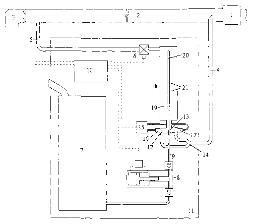
The following is an index of the reference numerals used in Figure 1:-
1. Fuel flow meter.
2. Fuel delivery pipe.
3. Fuel delivery nozzle.
4. Local flow inlet duct.
l0 5. Local flow outlet duct.
6. Isolating valve.
7. Dye tank.
8. Injection pump.
9. Dye line.
10. Controller.
11. Sealed cabinet.
12. Inspection chamber.
13. Inspection chamber dye outlet.
14. Local flow duct division.
15. Light sensor.
16. Light emitter.
17. Light receiver.
18. Blender.
19. Blender main chamber.
20. Blender manifold.
21. Manifold outlets.
Referring to Figure 1, there is shown part of the delivery system of a fuel
tanker truck,
including the fuel flow meter 1, a section of the fuel delivery pipe 2
downstream of the flow
meter 1 and the fuel delivery nozzle 3. Undyed fuel is stored in the truck
tank compartments
CA 02441222 2003-04-08
WO 01/27022 PCT/IE00/00120
-11-
and is pumped to the delivery nozzle 3 via the fuel flow meter 1 and delivery
pipe 2. The
delivery system also comprises a flexible hose and reel between the nozzle 3
and section of
delivery pipe 2 which is not shown in the figure. Some delivery systems, again
not shown in
the figure, comprise two nozzles and two flexible hoses and reels, one set
being dedicated to
dyed fuel and the other to undyed fuel.
Dye is pumped into the delivery system in a two stage process when dyed fuel
is required. In
the first stage, the dye is added to a flow of fuel in a duct, comprising a
parallel flow of the
delivered fuel, in precise direct ratio to the flow measured by the main truck
delivery meter.
In the second stage, the duct or parallel flow rejoins the main flow to give
the correctly
blended dyed product. The flow of fuel into which the dye is added is termed
the local flow of
fuel. In the preferred embodiment, the parallel flow is the local flow. In
alternative
applications, the parallel circuit is omitted and dye is added directly into
the main flow of
fluid.
~5
Local flow takes place in a parallel circuit duct comprising an inlet pipe 4
and outlet pipe 5.
Flow in the delivery pipe gives rise to a pressure drop between the inlet and
outlet points on
the delivery pipe 2 and promotes flow in the local flow duct 4,5 when an
isolating valve 6 on
the circuit is open. The isolating valve 6 is opened or closed when a delivery
is required as
dyed or undyed, respectively.
The first stage comprises a dye tank 7 for storing the dye and an injection
pump 9 which
injects discrete quantities of dye into the local flow. The injection pump 8
is an air -driven
piston and plunger type with inlet and outlet non-return valves. The system
uses dye in a
highly concentrated formulation. A blender 18 mixes the dye with the fuel in
the local flow.
The system is provided with an electronic controller, such as a PLC
(programmed logic
controller), computer or microprocessor 10, henceforth referred to as the
controller, which
monitors and controls the operation and security of the dye adding process.
The fuel flow
CA 02441222 2003-04-08
WO 01/27022 PCT/IE00/00120
-12-
meter 1 is provided with an electronic pulse output which delivers pulses to
the controller 10
in proportion to the flow of fuel passing through it.
The principal components of the apparatus are located in a secure sealed
cabinet 11 which can
only be accessed by authorised personnel.
An aspect of the invention is that when dye is added to the fluid it is
deliberately added in
discrete or varying amounts in order that changes in light transmitting
characteristics can be
detected in the resulting mixture of dye and fluid. A piston plunger type
injection pump
delivering discrete amounts of dye in a repeating cycle is conveniently used
to provide the
required changes. The process of dye addition can then be verified by checking
that the light
characteristics are appropriately altered when dye is added and that flow is
taking place by
checking that the light characteristics are restored to the status they had
prior to dye being
added. The method continuously checks its own ability to detect the dyed and
undyed
characteristics. The check related to fuel flow also checks against the
possibility of dye being
injected into a stationery mass of fuel while undyed fuel was being diverted
elsewhere.
The operation of the dye adding process is sensed by an apparatus comprising
an inspection
region of the fluid within an inspection chamber 12 positioned on the local
flow and an
2o inspection means comprising a light sensor. The apparatus allows a light
beam to be emitted
and received through a path in the fuel flowing through the inspection chamber
12.
A portion of the dye pulse from the injection pump 8 and dye line 9 is ducted
into the
inspection chamber 12 and enters the light path of the light beam, either
directly or mixed with
the flowing fuel. The dye is then carried out of the inspection chamber by the
local flow of
fuel, causing the strength of the mixture of dye and fuel in the inspection
chamber to revert to
fuel without dye.
In a preferred embodiment, a light beam is generated by an emitter 16 which is
external to the
chamber 12 and enters it through a small window at one end. The beam exits
through a
CA 02441222 2003-04-08
WO 01/27022 PCT/IE00/00120
-13-
second small window where it is received by an external receiver 17. The
emitter 16 and
receiver 17 are connected to a light sensor 15 by means of optic fibres.
In an alternative arrangement, the light beam is reflected by a target or by a
reflector within
the inspection chamber and exits back out through the same window through
which it entered
the inspection chamber. This arrangement doubles the length of the light path
for a given
length of inspection chamber and makes both optic fibre ends accessible from
the same end of
the apparatus. However, the received light beam may become too weak where a
target or
multiple faceted reflector is used. A stronger reflected beam can be achieved
by using a
simple reflecting surface, but alignment of the beam to the receiver may
become more
difficult.
The inspection chamber is arranged such that dye is introduced into the light
path when an
injection stroke occurs and is rapidly removed from the chamber following the
injection
stroke. This is achieved by arranging the inspection chamber to be such that
its volume is less
.. or significantly less than the volume which flows through the inspection
chamber over the
period of time between injection pump strokes and by arranging the geometry to
avoid
stagnant regions in the chamber where dye might remain trapped from one
injection stroke to
the next.
In a variation of the invention, the geometry is arranged to give some degree
of differential
flow in the inspection chamber, with some regions flowing faster than others.
The reason for
this is to allow a more gradual removal of dye from the inspection chamber and
thereby allow
a qualitative measure of the process to be carried out. This is discussed in
greater detail later
in the specification.
In the preferred embodiment, the apparatus is provided with a fuel inlet
division 14 where the
inflow of fuel is divided into two inflow channels which flow into opposite
ends of the
inspection chamber 12, are reunited in the chamber 12 and exit from one point.
The light path
3o enters at one inflow channel, substantially in the direction of flow, and
exits at the other inflow
CA 02441222 2003-04-08
WO 01/27022 PCT/IE00/00120
-14-
channel, substantially against the direction of flow. This arrangement
provides several
advantages.
Firstly, it keeps dye away from the lenses or windows through which the light
beam is emitted
and received, and thereby reduces the possibility of staining or contamination
or any other
undesirable effect which might arise from direct contact with the dye.
Secondly, it allows the dye outlet 13 to be positioned close to the exit from
the light path,
thereby allowing the dye to clear rapidly from the light path following the
injection stroke.
1o Thirdly, it prevents the possibility of dye being temporarily retained in
regions of slow or
stagnant fluid movement, such as at regions or crevices close to the lenses or
windows,
Fourthly, it allows a relatively long light path through the inflowing base
fluid without
compromising the need to rapidly clear dye from the light path, and thereby
allows the
possibility of improved inspection of the incoming fuel.
In the preferred embodiment, the light path is arranged to be substantially
horizontal. This has
the following advantages. Firstly, it reduces the risk of contamination of the
windows by
debris or settlement of suspended matter under the influence of gravity.
Secondly, it reduces
the risk of air or gas pockets arising or being trapped adjacent the windows.
Such pockets
2o could affect the light path or could promote contamination of the windows
by allowing drying
out, filming or other reaction to occur which would not take place if the
window remained
submerged.
A narrow beam of parallel light in the light path can be completely disrupted
by a single air or
gas bubble, due to reflection at the curved surface of the bubble. Various
precautions, which
are adopted in the preferred embodiment, shall now be described to prevent
bubbles affecting
the operation of the device.
A first precaution involves ensuring that the channels, through which the
light beam passes,
3o are arranged in a manner which ensures that bubbles are carried out by the
flow of fluid
CA 02441222 2003-04-08
WO 01/27022 PCT/IE00/00120
-15-
through the channels. The channels are arranged such that they are
substantially horizontal or
sloping upwards in the direction of flow. The cross section of the channels is
made
sufficiently small to ensure that the fluid velocity remains adequate to
prevent bubbles
becoming lodged.
A second precaution involved ensuring that the channels are arranged with
sufficient space
above the light beam to allow small bubbles to be carned above the light beam,
such bubbles
naturally tending to rise due to buoyancy.
A third precaution involves arranging the controller such that it does not
interpret a brief
intermittent interruption of the light beam as an indication that fuel is
dyed. Where the
interruption is caused by a passing bubble, it will pass through the light
beam in a time period
related to the flow of fuel. The controller is programmed to ignore brief
interruptions of
duration approximately corresponding to the passage of a small element of
fluid through the
light beam channel with an additional duration to allow for its average speed
being sometimes
less than that of the fluid flow. Where deemed appropriate, the controller may
allow for an
interruption of more than one bubble, where the duration of the interruption
or where the
statistical occurrence of such interruptions differs clearly from the expected
interruption
arising from the presence of dyed fuel.
The apparatus further comprises a means for emitting and receiving the light
beam. The
apparatus is operable to detect a change in the received light beam which has
passed through
the inspection chamber when the fuel is uncoloured and when it is coloured by
the dye.
The detected change may be a change in the intensity or energy of the light or
a change in the
colour or hue of the light. The dye alters the light passing through the dyed
fuel by absorption
and by reflection. These changes can be detected or measured with electronic
light sensors.
Light sensors which detect changes in light intensity tend to be simpler and
less expensive
than those which detect changes in colour. However, those which detect changes
in colour
3o have the relative advantage that they are less sensitive to contamination
of the lens or windows
CA 02441222 2003-04-08
WO 01/27022 PCT/IE00/00120
-16-
required with optical equipment, and are less sensitive to changes in the
colour or other
characteristics of the fuel.
Light sensors are available in various forms, including photodiode and
photoresitor types.
Light sensors are also available in packaged form where a target or threshold
value can be set
for the light characteristic and where an on or off output is signalled when
the target value is
reached. A photodiode light sensor of this type is used in the preferred
embodiment of the
invention. These types are commonly used for solid object detection in
industrial applications
and are accordingly inexpensive. Alternatively, the output can be of the
analogue type where
to the signal is proportional to the relative strength of the sensed
characteristic of the right. This
can have advantages when qualitative monitoring of the dye adding process is
required.
However, it has the relative disadvantage that many controllers are not
capable of processing
analogue signals without the addition of further equipment.
i5 When the apparatus is in operation, the signals from the light sensor are
monitored by the
controller 10. The controller checks that dye injection has taken place by
detecting a reduced
or off signal immediately following the injection stroke. The controller
checks that fuel is
flowing in the inspection chamber by detecting the re-establishment of the
signal following the
reduced or off signal arising from the injection stroke. The controller can be
programmed to
2o take appropriate action if dye injection or the flow of fuel is not
detected or is inadequate.
Detection of the injected dye pulse is relatively straightforward with the
method of the
invention because the pulse is highly concentrated and is quite opaque when
injected before
mixing with the undyed fuel. Detection of the absence of local flow is also
straightforward
25 because the opaque mixture will not clear between one injection stroke and
the next if local
flow is absent.
A local flow rate of inadequate magnitude can also be detected by the method
of the invention
by using the apparatus to measure the length of time taken for the opaque
mixture to clear to a
CA 02441222 2003-04-08
WO 01/27022 PCT/IE00/00120
-17-
known state and by comparing its length of time to an expected value which has
been
predetermined by means such as trial and error.
Care must also he taken to ensure that false readings are not caused by
discoloration or gradual
build up of contaminants on the windows or the light sensor lenses.
The apparatus of the invention can also be used to check the incoming fuel, in
particular to
check that it has not already been dyed. The detection of possible double
dyeing of fuel can
be important where it is necessary to prevent a particular type of fraud
related to recirculating
l0 the fuel through the dye adding apparatus. Accurate detection of the dyed
status of the
incoming fuel is more difficult than detection of the concentrated dye pulse
because the
mixture is not opaque and the differences to be measured are much less
pronounced. In the
preferred embodiment, the length of travel of the light beam through the fuel
is deliberately
elongated to increase the degree of absorption of the light by the dye. The
degree of
15 absorption of the light varies exponentially with the length of the light
path and the
concentration of the dye in the fuel. The length of the light path is defined
as its length in the
fuel or fuel and dye mixture. The light path is arranged relatively long in
relation to the length
of the exit path of fluid from the inspection region, its length being several
times the length of
the exit path. The controller is programmed to take appropriate action if a
reduced or off
2o signal is detected at times other than following the injection stroke.
Detection of double dying or colour in the incoming fuel can be facilitated in
several ways
One method is to use a light sensor which detects colour rather than light
intensity. An
alternative preferred method uses a light sensor which detects light intensity
but with an
25 emitter or light source of a colour which is preferentially absorbed by the
dye. This is
achieved by using a light source of a colour such that the dye is of a
substantially subtractive,
complementary colour, for example a green light source is ideally used with
red dye, a blue
light source with yellow dye and a red light source with blue dye. Where a
green light source
is used where the dyed fuel colour is red and the undyed fuel varies from
clear to light amber,
30 the green light source is more readily absorbed by a red than an amber
medium and is thus
CA 02441222 2003-04-08
WO 01/27022 PCT/IE00/00120
-18-
more sensitive to dye in the fuel than it is to the degree of amber of the
base fluid or to light
contamination or yellowing of the window. Light other than visible light can
also be used
with the method of the invention
As mentioned previously, the detection of a regularly changing characteristic
has the
additional advantage that the apparatus is continually checking itself. For
example, if
dedicated light sensors were used to detect the condition of fuel in a part of
the apparatus
where it was expected to be always dyed or always undyed, a steady false
signal could readily
occur which incorrectly indicated the fuel condition, either by deliberate
misuse of the system
to or by accidental malfunction, such as contamination of the light sensor
windows or lenses,
blockage of the light emitter, or failure or overnde of the light sensor
itself.
In addition to monitoring the discrete parameters mentioned above, the
apparatus can also be
used to qualitatively monitor the dye additive process by measuring the time
taken or the
i5 amount of fuel passing through the fuel flow meter while the light sensor
signal changes from
one state to another and then comparing the result to a known value or to a
running average
value. This approach can be used to obtain comparative or qualitative
information on the
colour of the incoming fuel, the approximate volume of the injection stroke or
the approximate
rate of flow of fuel through the inspection chamber.
For example, the controller may count the number of electronic pulses received
from the fuel
flow meter over the interval between the injection stroke and the light sensor
detecting the
light intensity reverting to a value preset on the sensor. This preset value
may be the chosen
threshold value at which the sensor is set to distinguish between dyed and
undyed incoming
fuel. The controller may keep a running average of these numbers and identify
any newly
recorded number which significantly differs from the running average. By
maintaining a
record of this information, electronic or otherwise, a qualitative audit trail
is created for the
incoming fuel which can be readily cross referenced to customer deliveries.
This could be
used, for example, to determine a history of partial recirculation of fuel
through the dye adding
CA 02441222 2003-04-08
WO 01/27022 PCT/IE00/00120
-19-
apparatus, where the partial recirculation resulted in a mixture which was
sufficiently weak in
colour not to have been detected by the normal threshold setting value on the
light sensor.
Light sensors are sometimes provided with a separate output which indicates
that the light
intensity lies within a set range of the threshold value over a given period
of time to give
warning of a potential unstable output. This output may also be used to
provide an alternative
qualitative monitoring of the dye adding process similar to that already
described. For
example, the controller may count the number of electronic pulses received
from the fuel flow
meter whilst the unstable output is active. The number will increase as the
average light
l0 intensity condition gets closer to the threshold value.
The use of a running average assists in eliminating the effect of gradually
changing conditions
which might otherwise cause misleading results, such as gradual build up of
contamination on
the windows, seasonal changes in operating conditions or wear in the
apparatus.
The use of qualitative checks has the additional advantage that it further
increases the
difficulty of unauthorised interference, because manual simulation of the
qualitative results
would be more difficult than manual simulation of simpler on and off signals.
Usually, detection of the threshold value will cause a response such as a shut
down of the
apparatus and it is important that the threshold value is set sufficient high
that the response is
not unnecessarily activated, for example by the coincidence of several
contributing factors
such as an extreme in a normal operating condition, use of unusually dark but
undyed fuel or
minor contamination of the windows or lenses.
The controller is programmed to detect when breaches of security occur and on
detection of
such breaches it is additionally programmed to activate appropriate responses
such as the
prevention of further adding of dye to the fuel by shutting down the
apparatus. The responses
may also comprise the creation of records of the breaches and warnings to the
operator or
CA 02441222 2003-04-08
WO 01/27022 PCT/IE00/00120
-20-
warnings communicated back to the fuel distributor's base. The appropriate
level of responses
will usually be determined by the authorities and the fuel distributor.
The invention presents many advantages over the prior art methods in addition
to those
already discussed.
The invention presents the additional advantage that it provides a direct
confirmation that the
fuel has been coloured. This contrasts with the prior art methods which
disclose no means of
providing such confirmation. However, one prior art method attempts to inhibit
substitution
of dye by a spurious uncoloured fluid by providing the dye tank with an anti
flush section and
an anti draining means.
The invention also presents the advantage that it provides a direct
confirmation that dye has
been delivered into the fuel. This again contrasts with the prior art method
which only
provides an indirect confirmation by checking that a liquid pulse has taken
place in the pump.
There remains the uncertainty that the pulse might be deliberately or
accidentally diverted
before reaching the flow of fuel.
The invention presents the further advantage that it checks the flow of dye
independently of
2o temperature induced viscosity effects, This contrasts with the prior art
which relies on
detection of the movement of a member in a close bore being lifted by the
pulse and falling
back under gravity. Changes in viscosity may affect whether the member is
lifted or whether
it returns under gravity.
The invention presents the additional advantage that it checks the flow of dye
with equal
reliability for pulses of large or small volume. This again contrasts with the
prior art which
relies on detection of the movement of a member in a close bore being lifted
by the pulse and
falling back under gravity. This method cannot be reliably used with very
small pulses. The
use of very small pulses is of considerable importance where it is desired to
use a highly
3o concentrated dye.
CA 02441222 2003-04-08
WO 01/27022 PCT/IE00/00120
-21 -
The invention also presents the advantage that it checks that local fuel flow
is taking place
when the flow rate is very low compared to the normal flow rate. The prior art
discloses no
method for detecting such low local fuel flow. The detection of the movement
of a member in
a close bore being lifted by the pulse and falling back under gravity, as
disclosed for dye flow,
would not work where flow was required to be measured at rates which are very
low relative
to the normal maximum flow rate. Such low rates are required, for example,
when foaming
takes place in a tank or when a fill is being completed and there is no ready
indication of fuel
level.
to
The invention presents the further advantage that the apparatus has no moving
parts, In
additional to general long term reliability, this also avoids the possibility
of misreadings
caused by movement such as truck engine vibrations.
15 The invention presents an additional advantage where safety reasons require
that electrical or
electronic components in contact with fuel or dye meet safety requirements,
such as explosion
proof requirements. Such requirements can restrict the types of components
that can be used
or can increase their cost. The optic fibre connections, used in the apparatus
of the invention,
permit the electrical and electronic components, including the light sensor,
to be positioned
20 remotely from the inspection chamber and all points of potential contact
with the fuel or dye.
The light emitting and light receiving ends of the optic fibres are not
electrical or electronic
devices.
The apparatus also includes a blender 18 which comprises an elongate blender
main chamber
25 19 which is connected in line with the parallel circuit 4,5 and a blender
manifold 20. Dye is
pumped into the blender manifold 20 by the injection pump 9 which delivers
discrete amounts
of dye in a preset proportion to the amount of fuel passing through the fuel
flow meter 1. The
blender manifold 20 spreads the injection pulse along the length of the main
chamber 19.
CA 02441222 2003-04-08
WO 01/27022 PCT/IE00/00120
-22-
The cross sectional area of the main chamber 19 is arranged such that the
average time for the
flow of fuel to pass through it is greater that the interval between
injections from the injection
pump 8. This ensures that all of the fuel is dyed as it passes through the
main chamber 19. In
the preferred embodiment, the cross sectional area is arranged such that two
or three injections
take place over the average time for the fuel to pass to ensure overlap of the
elongated
injections from the blender manifold 20 and thereby promote more even mixing
of the dye and
fuel.
Referring again to Figure 1, the inspection chamber outlet 13 and the manifold
outlets 21 are
to shown as holes in the dye line 9 and blender manifold 20. These holes are
made relatively
small to ensure reasonably even flow from them when injection takes place. The
resistance to
fluid flow through the holes should be relatively high compared to the
resistance to fluid flow
through the tube bores connecting the dye line to the holes. The openings in
the manifold tube
are arranged such that leakage into or out of them is prevented in the
intervals between
injections. Such leakage could be caused by the pressure gradient along the
blender chamber
caused by the flow of fuel. It could also be caused by differences in density
between the dye
and fuel.
Figure 2 shows a preferred embodiment of the invention, where the holes 100
are additionally
2o provided with check valves 101 to prevent leakage. The check valves 101
comprise short
lengths of elastic tube 102 fitted over the dye bearing tube or manifold 9,20
with one end of
the elastic tube 102 covering the hole 100. The elastic tube is held in
position by a clip 103
which is located away from the hole 100. Dye under pump pressure can readily
lift the elastic
tube and escape into the inspection chamber 12 or main chamber 19. However,
dye under low
pressure is retained. Reverse flow into the dye bearing tube 9 or manifold 20
is prevented by
the elastic tube 102 covering the holes 100.
Refernng again to Figure 1, the inspection chamber dye outlet 13 is shown in
diagrammatic
form located on a continuation of the dye line 9 connecting to the blender
manifold 20. In
practice, the dye outlet 13 may be located in alternative arrangements such as
at the distal end
CA 02441222 2003-04-08
WO 01/27022 PCT/IE00/00120
- 23 -
of the connected dye line 9 and blender manifold 20 or on a separate tee-ed
off branch line
extension of the dye line 9 with its distal end closed. These alternative
arrangements may be
found more convenient for positioning the outlet 13 in the inspection chamber
12 or for
checking or servicing the check valve.
Problems may arise where the equipment is first used or where it has been
unused for a period
of time, due to the manifold not being fully filled with dye, in that dye
might not enter the
inspection chamber when the pump commences operation. Various precautions,
which are
adopted in the preferred embodiment, shall now be described to assist in
preventing or
to overcoming such problems.
A first precaution involves minimising the volume of the manifold between the
pump and the
inspection chamber hole. This will reduce the number of pump strokes necessary
to deliver
dye to the inspection chamber hole in circumstances where the manifold is not
filled with dye.
15 In ideal circumstances, a single dye stroke will carry dye to the hole.
A second precaution involves arranging the inspection chamber hole to be
nearer to the pump
than the other manifold holes, or to arrange the path to it to have lower flow
resistance than
that of the paths to the other holes. This will again help to reduce the
number of pump strokes
2o necessary to deliver dye to the hole in circumstances where the manifold is
not filled with dye.
A third precaution, where gas, such as air, may be present in the manifold,
involves arranging
the geometry of the manifold to cause dye to preferentially drain into or be
retained in the
portion of the manifold between the pump and inspection chamber hole. This
will assist in
25 ensuring that dye present in the manifold will be preferentially expelled
through the inspection
chamber hole at the next pump stroke.
The following arrangements provide an example of the apparatus of the
invention where dye is
to be added to fuel flow delivery rates varying over a range of 5-350 litres
per minute and
3o where fuel to dye concentration is 35,000:1 and the dyed fuel is coloured
red.
CA 02441222 2003-04-08
WO 01/27022 PCT/IE00/00120
-24-
The injection pump delivers a pulse of 1.4 ml of dye. The inspection chamber
is 8 cm in
length between the light sensor windows. The channels in the inspection
chamber are
arranged with a circular cross section and horizontal axis. The cross section
is l3mm in
diameter and the centre of the light path is positioned 3 mm below the centre
of the cross
section of the channel. The blender main chamber is 40 cm in length and 24 cm2
in cross
sectional area. The manifold runs almost the full length of the main chamber
and comprises a
tube which is 5 mm in outer diameter and 2-3 mm in internal diameter . The
tube conveying
dye into the inspection chamber is of the same profile. There are three to
four equally spaced
to apart holes in the manifold and one in the inspection chamber. The holes
are 0.7 mm in
diameter. The elastic tubes covering the holes have a free internal diameter
slightly less than
the outer diameter of the manifold and have a wall thickness of 1.5 mm and a
length of 20
15 The light sensor is an electronic through beam photodiode type in packaged
form with a
settable target or threshold setting and an on or off type output. The emitter
and receiver ends
are connected to the sensor housing by optic fibres. The light source is an
LED producing
monochromatic visible green light. The emitter and receiver are provided with
focusing lenses
which are mounted adjacent glass windows in cavities sealed to prevent
internal condensation
20 or ingress of dust or contaminants. One side of each window makes contact
with the fuel
contents of the inspection chamber.
It is to be understood that the invention is not limited to the specific
details described above
which are given by way of example only, and that various modifications and
alterations are
25 possible without departing from the scope of the invention as defined in
the appended claims.