Note: Descriptions are shown in the official language in which they were submitted.
CA 02442454 2003-09-25
P-X464
SNAP FITTING ELECTRICAL C~NNECT~R
FIELD OF THE INVENTION
This invention relates to an electrical connector for
connecting an electrical conductor to an electrical
junction box, and more specifically to an electrical
connector that can be readily connected to an electrical
junction box with a snap fit.
BACKGROUND OF THE INVENTION
Connectors for attaching an electrical conductor to an
electrical box or junction box are well known in the art.
~ur_h electric or junction boxes, fuse boxes and the like
are uniformly used in virtually all residential and
commercial buildings. As a result, such electrical boxes
have been standardized. Howeverr even though such
electrical boxes have been generally standardized, it has
been noted that while such boxes may conform to the
standards adopted, there still exists some slight
variations and deviations that occur within the accepted
limited of the established standard, as for example the
punch out opening formed in such electrical boxes may vary
slightly in size by small amounts. Such minor size
1
CA 02442454 2003-09-25
P-2464
variations can cause a connector used in such instance to
be improperly or not properly grounded.
It has also been observed that many of 'the commonly
known connectors are limited for use with only a specific
type of electrical conductor, e.g. applicable for use only
with helically wound armor or B~ type cable or for use with
non-metallic sheathed cables, or co-axial cables and the
like. Such known connectors are evidenced in U.S. Patents
1,725,883; 1,830,250, and 2,823,932 for metallic armor or
BX cables; U.S. Patents 2,445,633; 4,711,472 and 5,132,493
for non-metallic conductors; and U.S. Patents 3,544,'705;
3,631,738 and 7,788,582 for co-axial type cables.
Other connectors are known, as for example, as
evidenced by U.S. Patents 5,171,164 and 5,266,050. While
the connectors disclosed in said later patents are provided
with a spring steel adaptor to effect the securing of the
connector to an electrical box, some difficulty and
excessive force may be required to effect the connection,
as the connector does not provide any relief space to
accommodate the deflection of the spring tangs or fingers
during insertion through to knock out opening of an
electrical box. It has been further observed that proper
grounding may not be achieved in the event a given
electrical box has a knock out opening which may be
2
CA 02442454 2003-09-25
P-2464
slightly oversized or the connector is slightly undersized,
but still within the parameters of the adopted standards
for electrical box and associated connectors.
Other connectors having a retaining clip for use with
connectors far an electrical box are evidenced by U.S.
Letters Patent 5,189,258 and 5,.42,994. These patents
relate to a novel retaining clip for use with connectars
having a thread engaging portion that permits the securing
of a threaded connector to an electrical box without
threading the connector to the electrical box.
Accordingly, the instant invention is directed to
further improvements relating to means for more effectively
securing or connecting an electrical connector to an
electrical box in a manner to insure a positive grounding
despite any slight deviations of size that may occur within
the adapted standards far such electrical boxes and
associated connectors.
StIM~~'ARY OF TFiE Ii~IVENTION
An object of this invention is to provide an
electrical connector having a novel retaining means for
effecting a snap fit connection with an associated
electrical box that requires a minimum of force and a
maximum of ease.
3
CA 02442454 2003-09-25
P-2464
Another object is to provide an electrical connector
having an improved retaining ring that will insure a more
positive grounding effect despite any slight variations
that may occur either in the construction of the electric
box and/or the connector body.
Another object is to provide an electrical connector
capable of use with metallic armored cables, non-metallic
sheathed cable and/or co-axial cables and the like.
Another object is to provide an electrical connector
that is relatively simple in construction, positive in
operation and economical to fabricate.
The foregoing objects and other features and
advantages are attained by an electrical. connector having a
connector body provided with an inlet end having an inlet
opening sized to receive armored. cable, BX type conductors,
non-metallic sheathed conductors or co--axial cables and the
like, and an outlet end defining the outlet opening. The
connector body is provided with a radial outwardly
extending flange intermediate the inlet and outlet ends
thereof, and which intermediate flange functions as a stop
to limit the insertion of the connector through the knock
out opening of an electrical box.
The outlet end of the connector is provided with a
pair of spaced apart shoulders which define therebetween an
4
CA 02442454 2003-09-25
P-2464
annular recess or space which circumscribes the outlet end.
A radial outwardly extending end flange circumscribes the
outermost shoulder. A snap fit retaining ring formed of
suitable spring steel is loosely mounted on the spaced
apart shoulders wherein the opposed peripheral edges of the
retaining ring are confined between the intermediate flange
and the end flange defining the outlet end or opening of
the connector. The retaining or snap fit ring is provided
with two series of a plurality circumferentially spaced
tangs blanked out of the plane of the retainer or snap fit
ring which are arranged in the assembled position to
securely lock the connector in place to an electrical box,
and at the same time insure a positive grounding connection
therebetween despite any slight deviation in the size of
the knock out opening or outlet end of the connector.
The inlet end of the connector body is provided with
an inlet opening for receiving the outer armored or non-
metallic covering of a conductor cable. The inlet end is
further provided with opposed side walls which are
interconnected by a top wall. An adjustable clamping
member in the farm of a C shaped member is supported on the
inlet end of the connector to firmly secure the cable to
the inlet end of the connector. An adjusting screw secures
CA 02442454 2003-09-25
P-2464
the clamping member to the inlet portion by which the
Clamping member can be adjusted as required.
Other features and advantages will become readily
apparent in view of the drawings and detail description.
I~T 'THE DRAWINGS
Fi.g. 1 is a perspective plan view of the blank from
which the retaining ring embodied in the invention is
formed, shown in an intermediate stage of forming same.
Fig. 2 is a partial end view taken along line 2-2 on
Fig. 1.
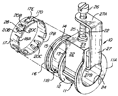
Fig. 3 is an exploded perspective view of an
electrical connector embodying the invention.
Fig. 4 is an exploded side view to illustrate the
manner in which the connector is adapted. to be secured to
an electrical box, and illustrating another similar
connector secured in place to another wall portion of an
e7_ectrical box.
Fig. 5 is a detail side view of the connector
embodying the invention connected to an electrical box.
Fig. 6 is a sectional side view taken along line 6-6
on Fig. 4.
6
CA 02442454 2003-09-25
P-2464
DETAIL DESCRIPTION
Referring to the drawings, there is illustration an
electrical connector 10 that embodies the instant
invention. As shown, the electrical connector 10 includes
a connector body 11 that has a cable or inlet end 11A and
an outlet end 11B. The connector body 11 may be formed as
a metal casting of any suitable metallic material such as
zinc, aluminum, and/or any suitable metallic alloy. A
radially outwardly extending intermediate flange 12
circumscribes the connector body 11 between the inlet end
11A and the outlet end 11B. The outlet end 11B is
generally circular and is provided with a pair of spaced
apart shoulders 13 and 14 circumscribing the outlet end 11B
that define therebetween a space or recess 15.
Circumscribing the innermost shoulder 14 is a radially
outwardly extending end flange 15.
In accordance with this invention, a specially
constructed retaining or snap fit ring 17 is loosely
supported on shoulders 13 and 14, as best viewed in Fig. 6.
The retainer or snap fit ring 17 is formed of a suitable
spring type steel. Referring to Figs. 1 and 2, the
retainer or snap fit retainer ring 17 is formed from a flat
blank 17A of spring steel having a width size sufficient to
extend to and ride on or be supported by shoulders 13 and
7
CA 02442454 2003-09-25
P-2464
14 in the assembled position, as best seen in Figs, 4 to 6.
The length of the blank 17A 1S SL7Ch that, when formed into
the retainer ring 17 as shown in Fig. 3, will define a
complete ring having an expandable circumference
sufficiently expandable to be fitted over the end flange 16
for positioning the same onto shoulders 13 and 14, as shown
in Fig. 6.
Referring to Figs. 1 and 2, the blank 17A of the
retaining ring 17 is formed with two series of tangs, e.g.
a series of A tangs and a series of B tangs. As shown, the
series A anal B tangs each include a plurality of similarly
constructed tangs arranged to be circumferentially and
alternately spaced about the circumference of the retainer
ring l7.in the assembled state, as shown in Fi.g. 3,
The tangs or spring fingers 18 or the series A tangs
are blanked out of the plane of blank 7_7A in a manner
whereby the free ends 18A of tangs 18 include a portion of
the longitudinal edge 17B of blank 17A that is adapted to
be supported on shoulders 13 in the assembled position, as
shown in Fig. C. The tangs 18 of the series A tangs are
bent outwardly of the plane of blank 17A in a cantilever
manner. The free ends 18A of the respective tangs 18 of
the series A tangs are then formed or arcuately shaped to
define a compound arch or curvilinear cross sectional
8
CA 02442454 2003-09-25
P-2464
shape, as best seen in Fig. 6. As will be hereinafter
described, the compounded curvilinear or rolled shape of
the free ends 18A of tangs 18 in both a transverse and
longitudinal direction will effect a positive grounding
connection with a metallic electric box 19.
The tangs 20 of ~..he series B tangs are blanked or die
cut out of the plane of the blank 17A intermediate of the
opposed longitudinal edges 17B and 17C. As best shown in
Fig. 1, the free ends 20A of tangs 20 are spaced inwardly
from the trailing edge 17B. Also, tangs 20 are bent
outwardly of the plane of blank 17A as noted in Fig. 2 and
Fig'. 6. Tangs 20 are formed with opposed outwardly bent
wing portions 20B. Tangs 20 are also provided with a
projecting tit or projection 20C. As best seen in Fig. 6,
the free ends of the wing portions 20B of tangs 20 engage
the inner surface 19A of the electrical box 19, as seen in
Fig. 6, while the projection or tit 20C engages the
periphery of the knock out hole 19C to a7_so insure positive
electrical grounding between the connector '10 and the
electrical box 19. The retainer ring blank 17A at one end
is provided with a notch 17D and a complementary tongue 17E
at the other end so that when formed into a ring, defines a
complete 360° ring 17. As shown in Figs. 3 and 5, the
tongue 17E is received in notch 17D in a manner to prohibit
9
CA 02442454 2003-09-25
P-2464
any lateral play between the tongue 17E and groove 17D. As
the ring 17 is formed of spring steel or other suitable
metallic spring like material, the formed ring 17 is
rendered sufficiently flexible to permit the retainer ring
17 to be assembled and supported onto the shoulders 13 and
14 of the outlet end 11B.
The outlet end 11B is provided with an end wall 21
having an elongated outlet opening 21A, the end wall 21
functioning as a stop for the cable covering or sheath, and
whereby the unsheathed conductors can be extended through
opening 21A.
The inlet portion 11A is generally of a shape for
receiving various types of cables or conductors, as herein
described. The inlet portion 11B is also provided with a
means for securing the sheathed cable within the inlet
portion 11A. In the illustrated embodiment, the securing
means include a pair of spaced apart end. wall_ extensions
22, 22 interconnected by a web or top wall 23 to define a
bridge extending to one side of the inlet opening 24. The
web or top wall 23 is provided with a tapped hole 25 for
receiving an adjusting screw 26. Operatively associated
with the adjusting screw 26 is a C shape clamp 27. As best
seen in Fig. 3, the clamp 27 includes spaced apart leg
portions 27A, 27B. The leg portion 27A is provided with an
CA 02442454 2003-09-25
P-2464
opening 28 for receiving the threaded shank of the
adjusting screw 26 and the lower leg portion 2?B being
connected to the other end of the adjusting screw 26. The
arrangement is such that when the adjusting screw 26 is
rotated in one direction or the other, the clamp 27 will be
moved into or out of the inlet end to effect the clamping
or unclamping of the sheathed conductor {not shown). As
best seen in Fig. 4, the lower leg portion 27B may be
arcuately shaped to provide for a more positive clamping
effect on the cable conductor.
In operation, with a connector 10 as described, and
referring to Figs. 4 to 6, it w~~..ll be noted that a workman
need only to insert the connector 10 through a knock out
hole 19B to effect a positive snap fit connection. On
inserting the outlet end 11B through the knockout opening
19B, the tangs 18 and 20 of the series A and B tangs wil:~
depress. In doing so, the recess or space 15 will function
as a relief to minimize the force necessary to effect the
insertion. This is because the tangs 18 and 20 can be
depressed into the relief space 15 and not against the
surface of the outlet end. As the intermediate flange 12
engages the wall of the junction box, the spring tangs 20
will spring outwardly whereby the free ends of the wing
portion 20B, 20B of the tangs 20 engage the inner surface
11
CA 02442454 2003-09-25
P-2464
19 of the electrical box while the projecting tit or
projection 20C engages the inner periphery of the knock out
hole 19B, as best seen in Fig. 6. Simultaneously, the
arcuate shaped free end 18A of tangs 18 of the series A
tangs will positively engage the edge of the knock out hole
19B, as best seen in Fig. 6. The arcuate shape of the free
end 18A of tangs 18 thus enable tangs 18 to make a positive
ground connection even if the knock out holes may vary
slightly in size from box to box or hole to hole.
From th.e foregoing, the described connector 10 can be
readily inserted with a snap fit with a minimum of
inserti0I1 force. At the same time, the tangs 18 and 20 of
the locking or retainer ring 17 are shaped to provz.de
positive grounding of the connector with the associated
electric box. The annular recess or space 15 provides a
relief which allows the tangs 18 and 20 to be depressed
into the underlying recess 15 to facilitate the insertion
of the connector.
With the construction described, it will. be further
noted that the connector 10 in the assembled position with
the electrical box 19 is firmly secured to the electrical
box as the electrical box wall is tightly squeezed between
the intermediate stop flange 12 and the retaining tangs 20,
as noted in Figs. 5 and 6, and thereby, virtually
12
CA 02442454 2003-09-25
P-2464
eliminates any play or movement between the connector 10
and its associated electrical box 19.
While the present invention has been described
with respect to a particular embodiment, it will be
understood that various modifications may be made without
departing from the spirit or scope of the invention.
13