Note: Descriptions are shown in the official language in which they were submitted.
CA 02442664 2003-09-26
WO 02/078493 PCT/US02/10203
-1-
MEMBRANE DEFLATION IN COMBINATION WITH RIGID SURFACES
Background
1. Field of the Invention
The present invention is related to inflatable devices, and, more
specifically, to
inflatable devices in combination with rigid surfaces, to a method for
deflating an inflatable
device, and to mechanisms for connecting a cover to an inflatable device.
2. Description of the Related Art
Inflatable devices are used in a variety of contexts where buoyancy or a
cushioned
support is needed, where space is limited or portability is desired. For
example, inflatable
mattresses, cushions and other body supports are used for applications such as
camping,
hospital bedding, and both occasional and everyday bedding in the home. Such
inflatable
devices have the additional advantage that the degree of inflation of the
support can be
adjusted to provide even support of an irregular object, such as a person.
Other examples of
inflatable devices include boats, rafts and other devices for use in the
water.
A variety of methods are known for providing a fluid, such as air, to inflate
an
inflatable device. Typically, a pump is used to supply fluid to an orifice in
the inflatable
device. In most instances, fluid is introduced into inflatable devices through
an inlet that
may be sealed to retain fluid within the inflatable device. The inlet may also
serve as an
outlet for deflating the inflatable device. A pump for use with an inflatable
device may
include a motor that drives an impeller, moving the air into, or out of, the
inflatable device.
Motorized pumps may be powered by electricity. Typically, such electricity is
provided by
a connection to standard house current or, where portability is desired, by
batteries.
One known inflatable device is adapted for use as a mattress and includes a
bladder
constructed to contain air in the shape of a mattress. The inflatable device
also includes a
pump connected to the bladder and adapted to inflate the bladder when
connected to
household electric current.
Summary
According to one embodiment of the present invention an inflatable device is
provided. The inflatable device includes a substantially fluid impermeable
bladder and an
outlet in the bladder. The inflatable device also includes a first
substantially rigid surface in
CA 02442664 2003-09-26
WO 02/078493 PCT/US02/10203
-2-
contact with a first surface of the fluid impermeable bladder and a second
substantially rigid
surface in contact with the first surface of the fluid impermeable bladder. In
this
embodiment, the first and second substantially rigid surfaces collectively are
in contact with
more than half of the first surface of the fluid impermeable barrier.
According to one embodiment of the present invention a method of deflating an
inflatable device is provided. The method includes positioning a first and a
second
substantially rigid surface in contact with a first surface of the inflatable
device such that the
first and second substantially rigid surfaces collectively are in contact with
more than half of
the first surface of the fluid impermeable barrier and applying pressure to at
least one of the
first and second substantially rigid surfaces to force air out of the bladder.
According to one embodiment of the present invention an inflatable device is
provided. The inflatable device includes a substantially fluid-impermeable
bladder and an
outlet disposed within the bladder. The inflatable device also includes a
covering layer
connected to a surface of the bladder that to provides access to the outlet, a
portion of the
t 5 covering layer covering the outlet including a tab, the tab being
removably connected to at
least one of a remaining portion of the covering layer and the bladder.
According to one embodiment of the present invention an inflatable device is
provided. The inflatable device includes a substantially fluid-impermeable
bladder and an
outlet disposed within the bladder. The inflatable device also includes a
covering layer
comprising an opening and an anchor positioned proximate to the outlet and
connected to
the bladder and the covering layer.
According to one embodiment of the present invention an inflatable device is
provided. The inflatable device includes a substantially fluid-impermeable
bladder and an
outlet disposed within the bladder. The inflatable device also includes an
anchor positioned
proximate to the outlet and connected to the bladder, lock connected to the
anchor, and a cap
hingedly connected to the lock.
According to one embodiment of the present invention an inflatable device is
provided. The inflatable device includes a substantially rigid work surface
sized for use as a
lap desk and a substantially fluid impermeable bladder connected to the
underside of the
work surface.
According to one embodiment of the present invention a book stand is provided.
The book stand includes first and second substantially rigid surfaces hingedly
connected to
one another and a substantially fluid impermeable bladder positioned between
the first and
CA 02442664 2003-09-26
WO 02/078493 PCT/US02/10203
-3-
second substantially rigid surfaces such that inflation and deflation of the
bladder adjusts an
angle between the first and second substantially rigid surfaces.
Brief Description Of Drawings
The foregoing and other advantages of the present invention will be more fully
appreciated with reference to the following drawings in which:
FIG. 1 is a side, elevational view of an inflatable device according to one
embodiment of the present invention;
FIG. 2 is a side, elevational view of the inflatable device of FIG. 1 in an
inflated
condition;
FIG. 3 is a perspective view of an inflatable device according to another
embodiment
of the present invention in use as a lap desk;
FIG. 4 is a perspective view of the inflatable device of FIG. 3 in a deflated
condition;
FIG. 5 is a side, elevational view of the inflatable device of FIG. 3;
FIG. 6 is a side, elevational view of the inflatable device of FIG. 3, in a
deflated
condition;
FIG. 7 is a cut-away, perspective view of an inflatable device according to
another
embodiment of the present invention;
FIG. 8 is a cut-away, perspective view of the inflatable device of FIG. 7;
FIG. 9 is a perspective view of one aspect of the present invention;
FIG. 10 is a perspective view of another aspect of the present invention;
FIG. 1 I is a perspective view of another aspect of the present invention;
FIG. 12 is a perspective view of another aspect of the present invention;
FIG. 13 is a perspective view of another aspect of the present invention;
FIG. 14 is a perspective view of another aspect of the present invention;
FIG. 15 is a perspective view of another aspect of the present invention;
FIG. 16 is a cross-sectional view of another aspect of the present invention;
FIG. 17 is a cross-sectional view of another aspect of the present invention;
FIG. 18 is a cross-sectional view of another aspect of the present invention;
FIG. 19 is a cut-away, perspective view of an inflatable device according to
another
embodiment of the present invention;
FIG. 20 is a perspective view of an inflatable device according to another
embodiment of the present invention;
CA 02442664 2003-09-26
WO 02/078493 PCT/US02/10203
-4-
FIG. 21 is a perspective view of the inflatable device of FIG. 20 in a
partially
deflated condition;
FIG. 22 is a side, elevational view of an inflatable device according to one
embodiment of the present invention in a deflated condition;
FIG. 23 is a side, elevational view of the inflatable device of FIG. 22 in a
partially
inflated condition; and
FIG. 24 is a side, elevational view of the inflatable device of FIG. 22 in a
partially
inflated condition.
Detailed Description
The present invention is directed to an inflatable device with rigid surfaces
and to a
method of deflating the inflatable device. It should be appreciated that
"inflatable," as used
herein, means inflation with air and any other fluids, including various gases
and liquids,
that may also be used to inflate the device of the present invention. In one
embodiment, the
inflatable device includes a substantially fluid impermeable bladder and an
outlet in the
bladder. The inflatable device also includes a first substantially rigid
surface in contact with
a first surface of the fluid impermeable bladder and a second substantially
rigid surface in
contact with the first surface of the fluid impermeable bladder. In this
embodiment, the first
and second substantially rigid surfaces collectively are in contact with more
than half of the
first surface of the fluid impermeable barner.
Refernng now to the figures and, in particular, FIGS. 1 and 2, an inflatable
device 10
according to one embodiment, may include a substantially fluid impermeable
bladder 20 and
an outlet 30 in bladder 20. Inflatable device 10 may also include a first
substantially rigid
surface 40 in contact with a first surface 44 of fluid impermeable bladder 20
and a second
substantially rigid surface 42 in contact with first surface 44 of fluid
impermeable bladder
20. In this embodiment, first and second substantially rigid surfaces 40, 42
collectively are
in contact with more than half of first surface 44 of fluid impermeable
barrier 20. In use of
this embodiment, pressure may be applied to first substantially rigid surface
40 at a single
point and substantially rigid surface 40 will distribute that pressure
generally evenly over a
large portion of the first surface of bladder 20. Accordingly, it is possible
to deflate bladder
20 by applying pressure to single points on substantially rigid surfaces 40,
42 to exhaust a
fluid from bladder 20 via outlet 30. Thus, one advantage of this embodiment is
that it
alleviates a situation in which pressure may be applied to one portion of a
bladder that
CA 02442664 2003-09-26
WO 02/078493 PCT/US02/10203
-5-
causes fluid to move to another portion of the bladder, and not to an outlet
of the bladder.
Furthermore, with two substantially rigid surfaces, bladder 20 may be deflated
by folding
substantially rigid surfaces 40, 42 towards one another, applying pressure to
bladder 20 and
deflating it via outlet 30.
An inflatable device having first and second substantially rigid surfaces 40,
42 may
be used in a wide variety of applications. For example, as illustrated in
FIGS. 1 and 2,
inflatable device 10 may be constructed as a bed or cot having an inflatable
mattress and
first and second substantially rigid surfaces 40, 42 in the form of a
supporting bed frame.
By way of an alternate example, as illustrated in FIGS. 3 - 6, this embodiment
may be used
as a lap desk where bladder 20 serves as a cushion for the desk and the desk's
work surface
serves as first and second substantially rigid surfaces 40, 42. It will also
be appreciated that
the present invention will find utility in other applications having one or
more substantially
rigid surfaces. For example, in one embodiment, the invention may be
constructed as a
sleep sofa, wherein bladder 20 serves as a mattress and the frame of the sleep
sofa forms at
least two substantially rigid surfaces which may be folded in upon one another
to deflate the
mattress and stow the bed. An example of an inflatable device 10 according to
the present
invention for use in a sofa bed 200 is illustrated in FIGS. 20 and 21. In
another
embodiment, inflatable device 10 may be constructed as a book stand, for
example as
illustrated in FIGS. 22-24. By a book stand, it is meant a device that
supports a work piece,
such as a book, magazine, paper tablet, laptop, or the like, at an inclined
angle, such as an
easel or other desktop. In such an embodiment, substantially rigid surfaces
40, 42 may
serve as a base for inflatable device 10 and a support surface for a work
piece, respectively.
Bladder 20 may serve as a mechanism for providing the desired angle between
the rigid
surfaces, with the angle and incline of one surface adjusted by the amount of
fluid in the
bladder. The substantially rigid surface used to support a work piece may
include structure,
such as a ridge or shelf, intended to prevent the work piece from slipping off
the support
surface.
Bladder 20 may be constructed in any manner and of any materials) capable of
retaining a desired fluid under a degree of pressure necessary for its
intended application.
For example, bladder 20 may be constructed of a substantially fluid
impermeable barrier and
may be shaped in accordance with its intended use. Where bladder 20 is
intended for use as
a mattress, bladder 20 may be constructed in the shape and thickness of a
conventional
mattress. As an alternate example, where bladder 20 is constructed to provide
support as a
CA 02442664 2003-09-26
WO 02/078493 PCT/US02/10203
-6-
lap desk as illustrated in FIGS. 3 - 6, bladder 20 may be constructed as a
half cylinder,
rectangular polygon or other shape that will adequately support a lap desk.
Bladder 20 may
also be designed to provide desired comfort and to add flexibility and
stability in positioning
the work surface and work pieces, such as providing the working surface and
materials on
the work surface at a desired work height. As another example, where
inflatable device 10
is constructed as a bookstand, bladder 20 may be constructed in a shape that
allows the
incline of the substantially rigid surface acting as a support for a work
piece to be adjusted.
Bladder 20 need not be constructed such that substantially rigid surfaces 40,
42 are parallel
to one another when it is fully inflated, as angles greater than 90 degrees
between the
substantially rigid surfaces (generally corresponding to the work piece being
held vertically)
will not typically be necessary in this embodiment. For example, in this
embodiment
bladder 20 could be generally cylindrical and arranged such that substantially
rigid surfaces
40, 42 are at right angles when bladder 20 is fully inflated. Bladder 20 may
also be sized
and arranged such that it prevents the angle between substantially rigid
surfaces 40, 42 from
exceeding a certain value, such as 90 degrees. For example, bladder 20 may be
constructed
such that it is fully inflated when the first and second substantially rigid
surfaces are at 90
degrees to one another and connected to first and second substantially rigid
surfaces 40, 42
such that the angle cannot be further increased.
Bladder 20 may include internal structure, such as ribs or partitions. For
example,
bladder 20 may be divided into two or more separate fluid containing
compartments.
Bladder 20 may also include internal structure to control the movement of
fluid within
bladder 20. For example, bladder 20 may include baffles or walls within
bladder 20 to
improve the flow of fluid when bladder 20 is inflated or deflated.
A wall of bladder 20 may be any thickness required to substantially contain a
fluid
under pressures at which bladder 20 will be used. A thickness of the wall of
bladder 20 may
depend upon material from which bladder 20 is constructed. For example, more
durable or
elastic materials may not require the wall of bladder 20 to be as thick as
less durable or
elastic materials. For example, for common materials, the wall of bladder 20
may be 4-32
mils (approximately 0.1-0.8mm) thick.
Bladder 20 may be constructed of any material or materials capable of
substantially
containing a fluid and forming a bladder 20 strong enough to withstand
pressure at which
bladder 20 is to be used. For example, bladder 20 may be constructed of a
polymeric
material such as a thermoplastic. Bladder 20 may be constructed from a
relatively
CA 02442664 2003-09-26
WO 02/078493 PCT/US02/10203
_7_
inexpensive, easy to work with and durable material. Some example materials
may include
polyvinyl chloride film and polyester. The manner of making bladder 20 may
depend on its
material of construction and configuration, as will be recognized by one of
ordinary skill in
the art.
Bladder 20 should include an outlet 30. Outlet 30 may be constructed in any
manner
and of any materials) that allow it to permit fluid to flow from inside
bladder 20 to outside
bladder 20 as desired. For example, outlet 30 may be a sealable opening, such
as a valve or
an orifice with a mating cap. Outlet 30 may also serve as an inlet for the
inflation of bladder
20. Examples of suitable structure for outlet 30 may be found in U.S. Patent
Nos. 6,237,621
to B1 and 5,367,726, which are hereby incorporated by reference in their
entirety. The
position and size of outlet 30 may be such that fluid within bladder 20 may be
expelled
rapidly enough to allow inflatable device 10 to be deflated in a reasonable
time. For
example, outlet 30 may be positioned where bladder 20 will not obstruct it as
inflatable
device 10 is folded up, and may be large enough to allow adequate air flow
with reasonable
folding effort. In one embodiment, outlet 30 may be at least 1 square inch,
and is preferably
at least about 1.5 square inches; in a particularly preferred embodiment the
area is at least
about 3.5 square inches. It should be appreciated that the desired surface
area of outlet 30
may be provided by a single opening, or several openings whose total area is
equal to the
desired area.
2o Substantially rigid surfaces 40, 42 may be constructed in any manner and of
any
materials) that allow substantially rigid surfaces 40, 42 to apply relatively
even pressure to
bladder 20 when substantially rigid surfaces 40, 42 have pressure applied to
them. For
example, substantially rigid surfaces 40, 42 may include a board or other
sheet of relatively
rigid material, a net or fence-like structure, or a flexible material, such as
cloth, held
sufficiently taut to apply relatively even pressure to bladder 20.
The nature of substantially rigid surfaces 40, 42 may vary with the intended
use of
inflatable device 10. For example, where inflatable device 10 is intended for
use as a bed or
cot, such as illustrated in FIGS. 1 and 2, substantially rigid surfaces 40, 42
may take the
form of a traditional mattress support. In some instances, such support may
include a
flexible material attached at its edges to a frame by springs, holding the
flexible material
relatively taut. In addition, second substantially rigid surface 42 may be
constructed in the
same or different manner from the first substantially rigid surface 40. As
will be clear to
CA 02442664 2003-09-26
WO 02/078493 PCT/US02/10203
_g_
those of skill in the art, substantially rigid surface 40, 42 may be
constructed of a wide
variety of materials, given a particular application.
Where inflatable device 10 includes more than one substantially rigid surface
40, 42,
substantially rigid surfaces 40, 42 may be connected to one another. For
example,
substantially rigid surfaces 40, 42 may be connected to one another such that
they may be
opposed to one another, thereby improving the efficiency of deflation of
bladder 20.
Connecting substantially rigid surfaces 40, 42 may also allow an angle between
them to be
maintained, such as for use as a book stand. For example, substantially rigid
surfaces 40, 42
may be connected via a hinge 50. Hinge 50 may be constructed in any manner
that connects
l0 substantially rigid surfaces 40, 42 and allows them to be moved toward one
another. For
example, hinge 50 may be a separately constructed mechanical hinge located
between and
attached to substantially rigid surfaces 40, 42 or may be a flexible material,
such as a portion
of bladder 20 between substantially rigid surfaces 40, 42, where bladder 20 is
connected to
substantially rigid surfaces 40, 42.
In some embodiments, bladder 20 may be connected to substantially rigid
surfaces)
40, 42. Otherwise, where first and second substantially rigid surfaces 40, 42
are used to
deflate bladder 20, bladder 20 may be forced out from between substantially
rigid surfaces
40, 42 where bladder 20 is not connected to substantially rigid surfaces 40,
42. Where it is
desired to connect bladder 20 to substantially rigid surfaces 40, 42, this
connection may take
any form where the connection is capable of maintaining bladder 20 in contact
with
substantially rigid surfaces 40, 42 during deflation. In some embodiments,
substantially
rigid surfaces 40, 42 may be integrally formed with bladder 20. In other
embodiments, the
connection may be detachable, allowing bladder 20 to be removed for cleaning,
repair,
replacement, and the like. For example, bladder 20 and substantially rigid
surfaces 40, 42
may be connected by hook and loop fasteners, snaps, zippers, buttons and
equivalents
thereto.
Bladder 20 may include additional materials to improve the utility and comfort
of
bladder 20. For example, bladder 20 may include outer layers or coatings for
durability,
support or comfort. In some embodiments, bladder 20 may be coated with a
material which
3o is more pleasant to the touch than the material from which bladder 20 is
constructed. Where
inflatable device 10 is for use in supporting a person, bladder 20 may also
include a layer to
provide additional comfort, particularly where the person is to contact
bladder 20.
Accordingly, for a variety of reasons bladder 20 may include one or more
covering layers
CA 02442664 2003-09-26
WO 02/078493 PCT/US02/10203
-9-
60, such as illustrated in FIGS. 7 and 8. For example, covering layer 60 may
be located on a
second surface of bladder 20, may improve the texture and feel of bladder 20
and, further,
may allow air and moisture to pass between a person and bladder 20, preventing
discomfort.
As another example, covering layer 60 may be a protective layer.
In one embodiment, covering layer 60 may cover outlet 30, preventing it from
interfering with the comfort of a person using inflatable device 10. Where
covering layer 60
covers outlet 30, outlet 30 may be made easily accessible. For example,
covering layer 60
may be constructed to be easily removed from bladder 20 or otherwise moved
aside from
outlet 30 (without removing the covering layer from the bladder or otherwise).
In one
to embodiment, covering layer 60 may be easily removed from bladder 20 in the
vicinity of
outlet 30. For example, referring to FIGS 7, 8 and 19, a portion of covering
layer 60 may be
removable from bladder 20 at an access point 110. Such portion of covering
layer 60 may
be constructed, for example, as a tab 70. Tab 70 may be constructed in any
shape that
allows it to selectively cover outlet 30 and not interfere with the comfort of
a person using
inflatable device 10. For example, tab 70 may include a securing device 111
for securing
tab 70 to outlet 30, covering layer 60 and/or bladder 20. For example, tab 70
may include a
snap, zipper, or hook and loop fastener (such as VELCRO~ hook and loop
fastener)
arrangement.
In another embodiment, covering layer 60 may not cover outlet 30. Whether or
not
2o covering layer 60 covers outlet 30, it is preferred that the entire
covering layer 30 also be
removable from bladder 20 so that it may be cleaned, repaired, replaced, and
the like. In
embodiments where covering layer 60 does not cover outlet 30, and is removable
from
bladder 20, it may be desirable to align an opening in covering layer 60 with
outlet 30 while
maintaining ease of removability of covering layer 60.
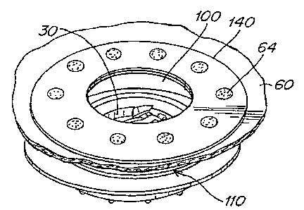
One embodiment of an inflatable device 10 comprising a removable covering
layer
60 is illustrated in FIGS. 9-18. In this embodiment, inflatable device 10 may
include
bladder 20, outlet 30, covering layer 60 having an opening 100, and an anchor
110
positioned proximate to outlet 30 and connected to bladder 20 and covering
layer 60. It
should be understood that the term "connected" does not imply a degree of
permanency.
3o For example, the connection between the covering layer and the anchor will
typically be
easily detachable, while the connection between the bladder and the anchor
will typically be
permanent.
CA 02442664 2003-09-26
WO 02/078493 PCT/US02/10203
-10-
Anchor 110 may have any structure that removably connects to covering layer 60
such that outlet 30 is accessible through opening 100 and that is sufficiently
firmly
connected to bladder 20 for a particular application. For example, as
illustrated in FIG. 11,
anchor 110 may include a lip 112 surrounding outlet 30. Lip 112 may be
contiguous, or
may be constructed of a plurality of smaller elements. Lip 112 may include
structure able to
mate with comfort layer 60. For example, lip 112 may include an overhang 114.
Anchor 110 may be constructed of any material that allows anchor 110 to be
removably connected to covering layer 60. Preferably, anchor 110 is
constructed of a
material that facilitates connection and disconnection of covering layer 110.
For example,
1 o anchor 110 may be constructed of a flexible, or even elastomeric, material
that is able to
deform to allow connection and disconnection of covering layer 60. Where
anchor 110
includes lip 112 and overhang 114, these may be flexed to allow opening 100 in
covering
layer 60 to fit over them. It should be appreciated that anchor 110 need not
be flexible in all
embodiments. For example, retainer 140 may allow sufficient flexing for
connection and
disconnection of retainer 140 and covering layer 60 to anchor 110, which may
be rigid.
Anchor 110 may be integrally formed with outlet 30, a valve structure 130, or
separately
constructed and connected. While this integrally formed arrangement is
convenient, it is not
required.
Opening 100 in covering layer 60 may be constructed in any manner that allows
access to outlet 30. Preferably, opening 100 is constructed to facilitate
removable
connection with anchor 110. For example, opening 100 may be sized and adapted
to mate
with anchor 110. In the illustrated embodiment, removable connection is
facilitated by a
retainer 140 positioned around opening 30. Retainer 140 may be constructed in
any shape
that allows it to removably connect with anchor 110. For example, where anchor
110
includes a circular lip, retainer 140 may include a ring.
Retainer 140 may be constructed of any material that allows it to removably
connect
with anchor 110. For example, retainer 140 may be constructed of a material,
such as
elastomeric material, that is able to be stretched over structure associated
with anchor 110.
In one embodiment, retainer 140 includes a polymeric material. Retainer 140
may include
3o multiple layers, such as multiple layers with covering layer 60 sandwiched
between them.
For example, retainer 140 may include two polymeric layers positioned on
either side of the
covering layer and connected together. Such a connection may be performed in
any manner
that provides sufficient durability. In one embodiment two polymeric layers
are radio
CA 02442664 2003-09-26
WO 02/078493 PCT/US02/10203
-11-
frequency (RF) sealed to one another to form retainer 140. Connection between
layers of
retainer 140 may be facilitated by modifying the structure of covering layer
60. For
example covering layer 60 may include a plurality of holes 62 (see FIG. 18) in
a portion of
covering layer 60 positioned between the two polymeric layers, such that the
polymeric
layers are in direct contact with one another at the holes. Locations where
the polymeric
layers are in direct contact with one another through the holes in the
covering layer are
labeled 64 in the figures.
In some embodiments, it may be desirable for retainer 140 to extend beyond the
edge
of the opening 100. This arrangement may allow two layers of retainer 140 to
be more
easily connected and may also result in an overall thinner structure to mate
with anchor 110.
For example, in a variety of embodiments covering layer 60 may be relatively
thick, such as
where it is quilted or constructed of heavy-duty materials. In such
embodiments, if covering
layer 60 is sandwiched between two layers to form retainer 140, the overall
structure may be
relatively thick and inhibit connection with certain anchors. For example,
where anchor 110
includes lip 112 and overhang 114, the distance beneath overhang 114, such as
between
overhang 114 and bladder 20, may be insufficient for retainer 140. This may be
remedied
by increasing this distance or by making retainer 140 thinner. For example, as
described
above, covering layer 60 and retainer 140 may be constructed such that
covering layer 60
only extends into the outer portion of retainer 140 and does not extend into
the portion of
retainer 140 that connects with anchor 110.
In some embodiments, it may be desired to secure the connection between
covering
layer 60 and anchor 110 with a lock 150. Lock 150 may be constructed in any
manner and
using any materials that allow it to facilitate maintaining the connection
between covering
layer 60 and anchor 110. In one embodiment, lock 150 may be positioned around
outlet 30
between overhang 114 and at least one of covering layer 60 and retainer 140.
In this
embodiment, it may be required to remove lock 150 before disconnecting
covering layer 60
from anchor 110. One suitable lock 150 may comprise a ring of elastomeric
material.
Inflatable device 10 may also include a cap 160 for outlet 30. Where
inflatable
device 10 includes cap 160, it may be desirable for cap 160 to be tethered to
inflatable
device 10 to inhibit loss of cap 160. In one embodiment, lock 150 may also
serve as a
tether, or a portion of a tether, for cap 160. In such an embodiment, the
tether may be an
extension of lock 150. The tether, remainder of lock 150 and cap 160 may be
formed as one
piece or irreversibly connected. However, according to one embodiment of the
present
CA 02442664 2003-09-26
WO 02/078493 PCT/US02/10203
-12-
invention, it is preferred that lock 150 and cap 160 be reversibly
connectable. For example,
cap 160 and lock 1 SO may include mating structures, such as a slot 121 and
mating "T"
shaped element 122 (see FIG. 13). In addition to allowing cap 160 to be
detached from
inflatable device 10 without removing lock 150, an arrangement of two mating
structures
may provide a joint or hinge about which the cap may move. This arrangement
eliminates
the problem of prior art cap tethers constructed of a single piece of material
that develop a
"memory" for a shape and attempt to return to that shape. Typically, this
means that the cap
in such prior art devices tends to close itself and may obstruct outlet 30.
It should be appreciated that anchor 110 and lock 150 including a tether for a
cap
l0 160 may find utility where there is no covering layer, or where covering
layer 60 is not in
use. In particular, connection of a cap to a lock, ring, or similar structure
positioned on an
anchor using mating structures may have utility in many applications.
Inflatable device 10 of the present invention may be inflated in any manner
and
using any device capable of moving fluid into bladder 20. For example,
inflatable device 10
may be manually inflated by blowing into it or it may be inflated with a pump
80. Pump 80
may be any fluid pump, such as a conventional electric fluid pump. Pump 80 may
force
fluid through a conduit into, or out of, bladder 80. In some embodiments, the
conduit may
be positioned around the motor of the pump, as an annulus. According to one
embodiment
where a pump is used, the pump, such as pump 80, may be connected to bladder
20. Where
2o pump 80 is connected to bladder 20, pump 80 may be configured so that it
does not interfere
with the use of inflatable device 10.
Having thus described certain embodiments of the present invention, various
alterations, modifications and improvements will be apparent to those of
ordinary skill in the
art. Such alterations, variations and improvements are intended to be within
the spirit and
scope of the present invention. Accordingly, the foregoing description is by
way of example
and is not intended to be limiting. The present invention is limited only as
defined in the
following claims and the equivalents thereto.