Note: Descriptions are shown in the official language in which they were submitted.
CA 02442973 2003-09-26
r
CONTROL SYSTEM FOR CENTRIFUGAL PUMPS
10
20 BACKGROUND OF THE INVENTLON
IOOOa~ Field of the Invention -- The present
invention relates generally to pumping systems, and
more particularl~r, to methods for determining
operating parameters and optimizing the performance of
centrifugal pumps, which are rotationally driven and
characterized by converting mechanical energy into
hydraulic energy through centrifugal activity.
100031 Centrifugal pumps are used for transporting
fluids at a desired flow and pressure from one
location to another, or in a recirculating system.
Examples of such applications include, but are not
limited to: oil; water or gas wells, irrigation
systems, heating and cooling systems, multiple pump
systems, wastewater treatment; municipal water
treatment and distribution systems.
MDJ1013131 1,
CA 02442973 2003-09-26
C0004] In order to protect a pump from damage or to
optimize the operation of a pump, it is necessary to
know and control various operating parameters of a
pump. Among these are pump speed, pump torque, pump
efficiency, fluid flow rate; minimum required suction
head pressure, suction pressure,, and discharge
pressure.
[0005] Sensors are frequently used to directly
measure pump operating parameters: In many
applications, the placement required for the sensor or
sensors is inconvenient or difficult to access and may
require that the sensors) be exposed to a harmful
environment. Also, sensors add to initial system cost
and maintenance cost as, well as decreasing the overall
reliability of the system.
[0006] Centrifugal pumping systems are inherently
nonlinear. This presents several difficulties in
utilizing traditional closed-loop control algorithms,
which respond only to error between the parameter
value desired and the parameter value measured. Also,
due to the nature of some sensors, the indication of
the measured parameter suffers from a time delay, due
to averaging or the like. Consequently, the non-
linearity of the system response and the time lag
induced by the measured values makes, tuning the
control loops very difficult without introducing
system instability. As such, it would be advantageous
to predict key pump parameters and utilize each im a
feed forward control path, thereby improving
controller response and stability and reducing sensed
parameter time delays.
[0007] As an example, in a methane gas well; it is
typically necessary to pump water off to release
trapped gas from an underground formation. This
MW1013131 2
CA 02442973 2003-09-26
process is referred to as dewatering, where wa er is a
byproduct of the gas production. The pump is operated
to control the fluid level within the well, thereby
maximizing the gas production while minimizing the
energy consumption and water byproduct.
[0008] As another example; in an oil well, it is
desirable to reduce the fluid level above the pump to
lower the pressure in the casing, thereby increasing
the flow of oil into the well and allowing increased
production. This level is selected to reduce the
leve r as much as possible while still providing
sufficient suction,pressure at the pump inlet: The
minimum required suction head pressure of a pump is a
function of its design'and opera ing point.
[0009] Typically, centrifugal pumps are used for
both oil and gas production. Generally, the fluid
level is sensed with a pressure sensor inserted near
the intake or suction side of the pump, typically 1000
to 5000 feet or more below the surface. These down-
hole sensors are expensive and suffer very high
failure rates, necessitating frequent removal of the
pump and connected piping to facilitate repairs.
[0010] As fluid is removed, the level within the
well drops until the inflow from the formation
surrounding the pump casing equals the amount of fluid
being pumped out. The pump flow rate may be reduced
to prevent the fluid level from dropping too far. At
a given speed and flow, there is a minimum suction
pressure which must be met or exceeded to prevent a
condition that could be damaging to the pump.
[0011] Accordingly, it is common practice to
monitor the fluid level within the well and control
the operation of the pump to prevent damage. This
requires the use of downhole sensors.
MW1013131
CA 02442973 2003-09-26
~...- S~.._
[0012] Downhole sensors are characterized by cost,
high maintenance and reliability problems. Likewise,
the need for surface flow sensors adds cost to the
pump system. The elimination of a single sensor
improves the installation cost, maintenance cost and
reliability of the system.
[0013] Also, centrifugal pumps are inefficient when
operating at slow speeds and/or flows, wasting
electrical power. Therefore, there is a need for a
method which would provide reduced flow without
sacrificing overall efficiency.
(0014] Accordingly, it is an objective of the
invention to provide a method for es imating the flow
and pressure of a centrifugal pump without the use of
down hole sensors. Another objective of the invention
is to provide a method for determining pump suction
pressure and/or fluid levels in the pumping system
using the flow and pressure of a centrifugal pump
combined with other pumping system parameters.
Another objective of the invention is to provide a
method for using closed loop control of suction
pressure or fluid level to protect the pump from
damage due to low or lost flow. Another objective of
the invention is to provide a method for improving the
dynamic performance of closed loop control of the
pumping system. Other objectives of the invention are
to provide methods for improving the operating flow
range of the pump, for using estimated and measured
system parameters for diagnostics and preventive
maintenance, for increasing pumping system. efficiency
over a broad range of flow rates, and for
automatically controlling the casing fluid.level by
adjusting the pump speed to maximize gas production
from coal bed methane wells:
MW1013131 4
CA 02442973 2003-09-26
t
[0015] The apparatus of the present invention must
also be of construction which is both durable and long
lasting, and it should also require little or no
maintenance by he user throughout its operating
lifetime. In order to enhance the market appeal of
the apparatus of the present invention, it should also
be of inexpensive construction to thereby afford it
the broadest possible market . Finally, it is also an
objective that all of the aforesaid advantages and
objectives be achieved without incurring any
substantial relative disadvantage.
SUMMARY OF THE INVENTION
[0016] The disadvantages and limitations of the
background art discussed above are overcome by the
present invention. With this invention, there is
provided a method of continuously determining
operational parameters of a down hole pump used in
oil, water or gas production. In one embodiment,
wherein the pump is a centrifugal pump, the pump is
rotationally driven by an AC electrical drive motor
having a rotor coupled,to the pump for rotating the
pump element. In deep wells, it is common practice to
use an AC electrical drive motor designed to operate
at voltages that are several times that of
conventional industrial motors. This allows the motors
to operate at lower currents, thereby reducing losses
in the cable leading from the surface to the motor.
In those cases, a step ug transformer can be used at
the surface to boost the typical drive output voltages
to those required by the motor.
[0017] The method comprises the steps of
continuously measuring above ground the electrical
voltages applied to the cabla leading to the drive
MW1013131 5
CA 02442973 2003-09-26
~L . 4 i
-..., '~s.~...~
motor to produce electrical voltage output signals;
cantinuously measuring above ground the electrical
currents applied to the drive motor through the cable
to produce electrical current output signals; using a
mathematical model of the cable and motor to derive
values of instantaneous electrical torque from the
electrical voltage output signals and the electrical
current output signals; using a mathematical model of
the cable and motor to derive values of instantaneous
motor velocity from the electrical voltage output
signals and the electrical current output signals; and
using mathematical pump and system models and the
instantaneous motor torque and velocity values to
calculate instantaneous values of operating parameters
of the centrifugal pump system. In systems using a
step up transformer, electrical voltages and currents
can be ' measured at the input to the step up
transformer and a mathematical model of the step up
transformer can be used to calculate the voltages and
currents being supplied to the cable leading to the
motor. In one embodiment, the method is used for
calculating pump flow rate, head pressure, minimum
required suction head pressure, suction pressure, and
discharge pressure. In another embodiment, used when
accurate calculation of pump flow rate is difficult or
impossible, the flow rate is measured above ground in
addition to determining the motor currents and motor
voltages, and the method is used to calculate head
pressure, minimum required suction head pressure,
suction pressure, and discharge pressure.
(0018] The invention provides a method of deriving
pump flow rate and head pressure from the drive motor
and pumping unit parameters without the need for
external instrumentation, and in particular, down hole
MW101313'1 6
CA 02442973 2003-09-26
s r. ,
sensors. The self-sensing control arrangement
provides nearly instantaneous readings of motor
velocity and torque which can be used for both
monitoring and, real-time, closed-loop control of the
centrifugal pump. In addition, system identification
routines are used to establish parameters used in
calculating performance parameters that are used in
real-time closed-loop control of the operation of the
centrifugal pump.
[00l9] In one embodiment, wherein the operating
parameters are pump head pressure and flow rate, the
method includes the steps of using the calculated
value of the flow rate at rated speed of the pump
under the current operating conditions and the'
instantaneous value of motor speed to obtain pump
efficiency and minimum required suction head pressure.
The present invention includes the use of mathematical
pump and system models to relate motor torque and
speed to pump head pressure, flow rate and system
operational parameters. In one embodiment, this is
achieved by deriving an estimate of pump head pressure
and flow rate from motor currents and voltage
measurements which are made above ground. The results
are used to control the pump to protect the pump from
damage, to estimate system parameters, diagnose
pumping system problems and to provide closed-loop
control of the pump in order to optimize the operation
of the pump. Protecting the pump includes detecting
blockage, cavitation, and stuck pump. Comparisons of
calculated flow estimates and surface flow
measurements can detect excess pump wear, flow
blockage, and tubing leaks.
[0020] The operation of a centrifugal pump is
controlled to enable the pump to operate periodically,
MW1013131
CA 02442973 2003-09-26
1~ 1
such that the pump can achieve a broad average flow
rangewhile maintaining high efficiency. This
obviates the need to replace a centrifugal pump with
another pump, such as a rod beam pump, when fluid
level or flow in the well decreases over time. In
accordance with another aspect of the invention, a
check valve is used to prevent back flow during
intervals in which the pump is turned off.
[0021] In accordance with a further aspect of the
invention, an optimizing technique is used in the
production of methane gas wherein it is necessary to
pump water off an underground formation to release the
gas. The optimizing technique allows the fluid level
in the well to be maintained near an optimum level in
the well and to maintain the fluid at the optimum
level over time by controlling pump speed to raise or
lower the fluid level as needed to maintain the
maximum gas production.
[0022] This is done by measuring and/or calculating
fluid flow, gas flow, casing gas pressure, and fluid
discharge pressure at the surface. Selected fluid
levels are used to .define a sweet zone. This can be
done manually or using a search algorithm. The search
algorithm causes the fluid level to be moved up and
down, searching for optimum performance. The search
algorithm can be automatically repeated at preset
intervals to adjust the fluid level to changing well
conditions.
[0023] Uses of the'self-sensing pump control system
also include, but are not limited to HVAC systems,
mufti-pump control, irrigation systems, wastewater
systems, and municipal water systems.
MW1013131 $
CA 02442973 2003-09-26
~'.._ s
DESCRIPTLON OF THE DRAWINGS
[0024] These and other advantages of the present
invention are best understood with reference' to the
drawings, in which:
[0025] FIG. l is a simplified representation of a
well including a centrifugal pump, the operation of
which is controlled by a pump control system in
accordance with the present invention;
[0026] FIG. 2 is a block diagram of the centrifugal
pump control system of FIG. 1;
[0027] FIG. 3 is a functional block diagram of a
pump Control system for the centrifugal pump of FIG. 1
when using estimated flow;
[0028] FIG. 4 is a functional block diagram of a
pump control system for the centrifugal pump of FIG. 1
when using measured flow;
[0029] FLG. 5 is a block diagram of .an algorithm
for a pump model of the centrifugal pump control
system of FIG. 3;
[0030]' FIG. 6 is a block diagram of an algorithm
for a pump model of the centrifugal pump control
system of FIG. 4;
[0031] FIG: 7 is a block diagram of an algorithm
for a system model of the centrifugal pump control
system of FIGS. 3 and 4;
[0032} FIG. 8 is a block diagram of an algorithm
for a fluid level feedforward controller of the
centrifugal pump control ystem of FIGS. 3 and 4;
[0033] FIG. 9 is a block diagram of an algorithm
for a fluid level feedback controller of the
centrifugal pump control system of FIGS. 3 and 4;
MW1013131
CA 02442973 2003-09-26
[0034] FIG. 10 is a simplified block diagram of an
algorithm for a vector controller of the centrifugal
pump control,systern of FIGS. 3 and 4;
[Q035] FIGS. I1 through 13 are a set of pump
specification curves for a centrifugal pump,
illustrating pump power, pump head, pump efficiency
and pump suction pressure required wherein each is a
function of pump flow rate at rated speed;
[0036 FIG. 14 is a diagram of a typical
installation of a centrifugal pump; illustrating the
relationship between the pumping system parameters;
[0037] FIG. 15 is a block diagram of the controller
of the pump control system of FIGS. 3 and 4; and
[0038] FIG. 16 i's a set of two curves comparing the
efficiency of a pumping system using duty cycle
control to the efficiency of a pumping system using
continuous rotary speed.
[00391 Variables used throughout the drawing have
the following forms A variable with a single
subscript indicates that the reference is to an actual
element of the system as in Tm for the torque of the
motor or a value that is known in the system and is
stable as in Xp for the depth of the pump. A variable
with a second subscript of 'm', as in Vmm for measured
motor: voltage; indicates that the variable is measured
on a real-time basis. Similarly; a second subscript
of 'e' indicates an estimated or calculated value like
Tme for estimated motor torque; a second subscript of
'c' indicates a command like Vmc for motor voltage
command; and a second subscript of 'f' indicates a
feedforward command like Umf for motor speed
feedforward command: Variables in bold type, as in Vs
for stator voltage; are vector values having both
magnitude and direction.
MW1013131 1 0
CA 02442973 2003-09-26
r s
.v.,.J
DETAILED DESCRIPTION OF THE PREFERRED EMBODIMENT
[0040] Referring to FIG. 1, the present invention
is described with reference to an oil well 30 wherein
oil is to be pumped from an underground farmation 22.
The well includes an outer casing 39 and an inner tube
38 that extend from ground level to as much as 1000
feet or more below ground level. The casing 39 has
perforations 26 to allow the fluid in the underground
formation to enter the well bore. It is to be
understood that water and gas can be combined with oil
and the pump can be used for other liquids. The
control apparatus can also be used for pumping water
only. The bottom of the tube generally terminates
below the underground formations.
[0041] A centrifugal pump of the type known as an
electric submersible pump (ESP) 32 is mounted at the
lower end of the tube 38 and includes one or more
centrifugal pump members 34 mounted inside a pump
housing. The pump members are coupled to and driven
by a drive motor 36 which is mounted at the lower end
of the pump housing. The tube 38 has a liquid outlet
41 and the casing 39 has a gas outlet 42 at the upper
end above ground level 31. An optional check valve 28
may be located on the discharge side of the pump 32 to
reduce back flow of fluid when the pump is off. These
elements are shown schematically in FIG. l:
[0042] The operation of the pump 32 is controlled
by a pump control system and method including a
parameter estimator in accordance with the present
invention. For purposes of illustration, the pump
control system 20 is described with reference to an
applicatioro. in a pump system that includes a
conventional electric submersible pump. The electric
MW10131~31 11
CA 02442973 2003-09-26
...
Y
submersible pump includes an electric drive system 37
connected to motor 36 by motor cables 35. A
transformer (not shown) is sometimes used at the
output of the drive to increase voltage supplied to
the motor. The motor rotate the pump elements that
are disposed near the bottom 33 of the well. The
drive 37 receives commands from controller 50 to
control its speed. The controller SO is located above
ground and contains all the sensors and sensor
interface circuitry and cabling necessary to monitor
the performance of the pump system.
[0043] The motor 36 can be a three-phase AC
induction motor designed to be operated from line
voltages in the range of 230 VAC to several thousand
VAC and developing 5 to 500 horsepower or higher,
depending upon the Capacity and depth of the pump.
Pump Control System
[0044] Referring to FIG. 2, there is shown a
simplified representation of the pump control system
20 for the pump 32: The pump control system 20
controls the operation of the pump 32. In one
embodiment, the casing fluid level is estimated using
pump flow rat-a and head pressure estimates which, in
turn, can be derived from values of motor speed and
torque estimates. , The pump flow rate and head
pressure estimates are combined with system model
parameters to produce a casing fluid level estimate.
In one preferred embodiment, a pump model and system
model are used to'produce estimated values of pump
flow rate and casing fluid level for use by a pump
controller in producing drive control signals for the
pump 32.
MW1013131 1 2
a s \ ~ 02442973 2003-09-26 t
[0045] Alternatively, the measured discharge flow
rate of the pump 32 can be obtained using measurements
from the surface flow sensor 59 and combined with the
estimates produced by the pump and system models to
produce the casing fluid level estimate. This is
particularly useful when the configuration of the pump
makes it difficult to accurately calculate pump flow
rate from the mechanical inputs to the pump.
[0046] While in a primary function the estimated
parameters are used for control,, the parameters also
can be used for other purposes. For example, the
estimated parameters can be compared with those
measured by sensors or transducers for providing
diagnostics alarms., The estimated parameters may also
be displayed to setup, maintenance or operating
personnel as an aid to adjusting or troubleshooting
the system.
[0047] In one 'embodiment, values of flow and
pressure parameters are derived using measured or
calculated values of instantaneous motor currents and
voltages, together with pump and system parameters,
without requiring down hole sensors,- fluid lever
meters, flow sensors, etc. The flow and pressure
parameters can be used to control the operation of the
pump 32 to optimize the operation of the system. In
addition, pump performance specifications and system
identification routines are used to establish
parameters used in calculating performance parameters r
that are used in real time closed-loop control of the
operation of the pump.
[0048] The pump control system 20 includes
transducers; such as above ground current and voltage
sensors, to sense dynamic variables associated with
motor load and velocity: The pump control. system
MW1013131 13
CA 02442973 2003-09-26
x
,-
further includes a Controller 50, a block diagram of
which is shown in FIG. 2. Above ground current
sensors 5l of interface devices 140 are coupled to a
sufficient number of the motor cables 35; two in the
case of a three phase AC motor. Above ground voltage
sensors 52 are connected across the cables leading to
the motor winding inputs: The current and voltage
signals produced by the sensors 5l and 52 are supplied
to a processing unit 54 of the controller 50 through
suitable input/output devices 53. The controller 50
further includes a storage unit 55 including storage
devices which store: programs and data files used in
calculating operating parameters and producing control
signals for controlling the operation of the pump
system. This self-sensing control arrangement
provides nearly instantaneous estimates of motor
velocity and torque, which' can be used for both
monitoring and real-time, closed-loop control of the
pump. For example, in one embodiment, instantaneous
estimates of motor velocity and torque used for real-
time, closed-loop control are provided at the rate of
about 1000 times per second.
[0049] Motor currents and voltages are sensed or
calculated to determine the instantaneous speed and
torque produced by the electric -motor operating the
pump. As the centrifugal pump 32 is rotated, the
motor 36 is loaded. By monitoring the motor currents
and voltages above ground, the calculated torque and
speed produced by the motor 36, which may be below
ground, are used to calculate estimates of fluid flow
and head pressure produced by the pump 32.
[0050] More specifically; interface devices 140
include the devices for interfacing the controller 50
with the outside world. None of these devices are
MW1013131 1 4
CA 02442973 2003-09-26
'w_...~'
located below ground. Sensors in blocks 5l and 52 can
include hardware circuits which convert and calibrate
the current and voltage signals into current and flux
signals. After scaling and translation, the outputs
of the voltage and current sensors can be digitized by
analog to digital converters in block 53. The
processing unit 54 combines the scaled signals with
cable and motor equivalent circuit parameters stored
in the storage unit 55 to produce a precise
calculation of motor torque and. motor velocity. Block
59 contains an optional surface flow meter which can
be used to measure the pump flow rate . Block 59 may
also contain signal conditioning circuits to filter
and scale the output of the flow sensor before the
signal is digitized by analog to digital converters in
block 53.
Pump Control
[0051.] Referring to FIG. 3, which is a functional
block; diagram of the pump control system 20 for a pump
32 where the pump flow rate to pump power relationship
allows pump flow rate to be calculated, the pump 32 is
driven by a drive 37 and motor 36 to transfer fluid
within a system 150. The operation of the motor 36 is
controlled by the dri~re 37 and controller 50 which
includes a pump model 60; system model 8O, fluid level
feedforward controller 90, fluid level feedback
controller 100, motor vector controller 130 and
interface devices 140.
[0052] More specifically; block 140, which is
located above ground, can include hardware circuits
which convert and calibrate the motor current signals
Im (consisting of individual phase current
.measurements Tum and Ivm in the case of a three phase
MW1013131 1 5
CA 02442973 2003-09-26
~L".. '~,,Ni'
motor) and voltage signals Vm (consisting of
individual phase voltage measurements Vum, Vvm, and
Vwm in the case of a three phase motor) into motor
current and flux signals: After scaling and
translation, the outputs of the voltage and current
sensors can be digitized by analog to digital
converters into measured voltage signals Vmm and
measured current signals Imm: The motor vector
controller 130 combines the scaled signals with cable
and motor equivalent circuit parameters to produce a
precise calculation of motor electrical torque Tme and
velocity Ume. Autorivatic identification routines can be
used to establish the cable and motor equivalent
circuit parameters.
[0053] The pump model 60 calculates the values of
parameters, such as pump flow rate Qpe, pump head
pressure Hpe, pump head pressure at rated speed Hre,
minimum required suction head pressure Hse; pump
efficiency Epe; and pump safe power limit Ple relating
to operation of the pump 32 from inputs corresponding
'to motor torque Tme and motor speed Ume without the
need for external flow or pressure sensors. This
embodiment is possible for pumps where the
relationship of pump flow rate to pump power at rated
speed, as shown in FIG. 13, is such that each value of
power has only one unique value of pump flow rate
associated with it throughout the range of pump flows
to be used. Further, the system model 80 derives
estimated values of the pump suction pressure Pse,
flow head loss Hfe; pump discharge pressure Pde and
the casing fluid level Xce from inputs corresponding
to discharge flow rate value Qpe and the head pressure
value Hpe of the pump. The fluid level feedforward
controller 90 uses the pump head pressure at rated
MW1013131 . 1 6
CA 02442973 2003-09-26
speed value Hre, flow head loss value Hfe and
commanded fluid level Xcc to calculate a motor speed
feedforward command Umf. The fluid level feedback
controller l00 compares the commanded fluid level Xcc
with static and dynamic conditions of the fluid level
value Xce to calculate a motor velocity feedback
command Ufc. Motor velocity feedback command Ufc and
feedforward command Umf are added in summing block 79
to yield the motor velocity command Umc.
[0054] Motor vector controller 130 uses the motor
speed command Umc to generate motor current commands
Imc and voltage commands Vme. Interface devices in
block 140, which can be digi al to analog converters,
convert the current commands Ime and voltage commands
Vmc into signals which can be understood by the drive
37. These signals are shown as Ic for motor current
commands and Vc for motor winding voltage commands.
In installations with long cables and/or step up
transformers, the signals Ic and Vc would be adjusted
to compensate for the voltage and current changes in
these components.
[0055] Referring to FIG. 4, which is a functional
block diagram of the pump control system 20 for a pump
32 where. the pump flow rate is measured above ground,
the pump 32 is driven by a drive 37 and motor 36 to
transfer fluid within a system 150. The operation of
the motor 36 is controlled by the drive 37 and
controller 50' which includes a pump model 260, system
model 80; fluid level feedforward controller 90; fluid
level feedback controller 100, motor vector controller
130 and interface devices 140.
[0056] More specifically; block 140, which is
located above ground, can include hardware circuits
which convert and calibrate the motor current signals
MW1013131 1 7
CA 02442973 2003-09-26
t a . n . . , . , n
'~; : l~ ~ ,
Y
Im (consisting of individual phase current
measurements Ium and Tvm in the case of a three phase
motor) and voltage signals Vm (consisting of
individual-phase voltage measurements Vum, Vvm, and
Vwm in the case of a three phase motor) into motor
current and flux signals. After scaling and
translation, the outputs of the voltage and current
sensors can be digitized by analog to digital
converters into measured voltage signals Vmm and
measured current s-ignals Lmm. The motor vector
controller 130 combines the scaled signals with cable
and motor equivalent circuit parameters to produce a
precise calculation of motor electrical torque Tme and
velocity Ume. Automa is identification routines can be
used to establish the cable and motor equivalent
circuit parameters.
[0057]. In this embodiment, block 140 also may
contain hardware circuits which convert above ground
flow rate into an electrical signal that can be
digitized by analog to digital converters into the
measured flow signal Qpm for use by the pump model 260
and the system model 80.
[00581 The pump model 260 calculates the values of
parameters pump head pressure Hpe, pump head pressure
at rated speed Hre, minimum required suction head
pressure Hse, pump efficiency Epe, and pump safe power
limit Ple relating to operation of: the pump 32 from
inputs corresponding. to flow Qpm as measured by a flow
sensor and motor speed Ume wi-thout the need for other
external sensors. This embodiment is used for pumps
where the relationship of pump flow rate to pump power
at rated speed is such that there is not a unique pump
flow rate for each value of pump power. Further, the
system model 80 derives estimated values of the pump
Mwloiaiai 1 8
CA 02442973 2003-09-26
'~~
r
suction pressure Pse, flow head loss Hfe, pump
discharge pressure Pde and the casing fluid level Xce
from inputs corresponding to discharge flow rate value
Qpm and the head pressure value Hpe of the pump . The
fluid level feedforward controller 90 uses the motor
speed value Ume; flow head loss value Hfe and
commanded fluid level Xcc to calculate a motor speed
feedforward command Umf. The fluid level feedback
controller 100 compares the commanded fluid level Xcc
with static and dynamic conditions of the fluid level
value Xce to calculate a motor velocity feedback
command Ufc. Motor velocity feedback command Ufc and
feedforward command'Umf are added in summing block 79
to yield the motor velocity command Umc.
[0059] Motor vector controller 130 uses the motor
speed command Umc to generate motor current commands
Imc and voltage commands Vmc. Interface devices in
block 140, which can be digital to analog converters,
convert the current commands Imc and voltage commands
Vmc into signals which can be understood by the drive
37. 'These signals are shown as Ic for motor current
commands and Vc for motor winding voltage commands.
In installations with long cables and/or step up
transformers, the signals Ic and Vc would be adjusted
to compensate for the voltage and current changes in
these components.
[0060] The controller 50 provides prescribed
operating conditions for the pump and/or system. To
this end, either pump model 60 or pump model 260 also
can calculate the efficiency Epe of the pump for use
by the controller 50 in adjusting operating parameters
of the pump 32 to determine the fluid level Xc needed
to maximize production of gas or produced fluid and/or
MW1013131 1 9
CA 02442973 2003-09-26
y1
Y
the fluid level: Xc needed~to maximize production with
a minimum power consumption.
[0061] The controller 50 {FIG. 3 and FIG. 4) uses
the parameter estimates to operate the pump so as to
minimize energy consumption; optimize gas flow, and
maintain the fluid level to accomplish the objectives.
Other inputs supplied to the controller 54, include the
commanded casing fluid level Xcc and values
representing casing pressure Pc and tubing pressure Pt
(FIG. 8). Values representing casing pressure Pc and
tubing pressure Pt may each be preset to approximate
values as part of the system setup or, as is
preferable in situatioris where these values are likely
to vary during operation of the system, the controller
50 can use values measured by sensors mounted above
ground and connected to the controller 50 through
appropriate signal conditioning and interface
circuitry.
[0062] The controller 50 (FIG. 3 and FIG. 4)
optimizes use of electrical power as the flow delivery
requirements change and can determine fluid level
without using down Yiole sensors and, in one preferred
e~odiment, without using surface flow sensors. As
will be shown, the control opera ions provided by the
controller 50 include the use of the pump model 60
(FIG. 3) or pump model 260 (FIG. 4) and system model
80 (FIG. 3 or FIG. 4) to relate mechanical pump input
to output flow rato and head pressure. In one
embodiment (FIG. 3),,.this is achieved by deriving an
estimate of pump flow rate from above ground
measurements~of motor current and voltage. In another
embodiment (FIG. 4), the pump flow rate is measured
using.a surface flow sensor. From the flow value thus
obtained, the pump head pressure, efficiency and other
MW1013131 2 ~
CA 02442973 2003-09-26
. i
pump operating parameters are determined using pump
curve data. The re ults are used to control the pump
32 to protect it from damage and to provide closed-
loop control of the pump 32 in order to optimize the
operation of the pumping system. Protecting the pump
32 includes detecting blockage, cavitation, and stuck
pump.
[0063] Moreover; the operation of the pump 32 can
be controlled to enable it to operate periodically,
such that the pump can operate efficiently at a
decreased average pump flow rate. This obviates the
need to replace the electric submersible pump with
another pump, such as a rod beam pump, when fluid
level'or inflow within the well decreases over time.
[0064] Further, in accordance with the invention,
the pump can be cycled between its most efficient
operating speed and zero speed at a variable duty
cycle to regulate average pump flow rate. Referring
to FIG. 1, in case where electric submersible pumps
are being operated at a low duty cycle, such as on for
twenty-five percent of the time and off for seventy-
five percent of the time, a check valve 28 may be used
down hole to prevent back flow of previously pumped
fluid ' during the pomion of each cycle that the pump
is off. The check valve 28 can be.designed to allow a
small amount of leakage. This allows the fluid to
slowly drain out of the tube 38 to allow maintenance
operations.
Pump Model
[065) Reference is now made to FIG. 5, which is a
block diagram of an algorithm for the pump model 60 of
the pump 32 as used in the embodiment shown in FIG. 3
where it is possible to calculate an estimate of pump
MW1013131 2 1
CA 02442973 2003-09-26
~ ~.
flow xate. The pump model 60 is used to calculate
estimates of parameters including head pressure Hpe,
fluid'fiow'Qpe, minimum_required suction head pressure
Hse, pump mechanical input power limit Ple,~ and pump
efficiency Epe. In one preferred embodiment , the
calculations are carried out by the processing unit 5.4
(FIG. 2) under the control of software routines stored
in the storage devices 55 (FIG. 2). Briefly; values
o~ motor torque Tme and motor speed Ume are used to
calculate the mechanical power input to the pump Ppe
which is used with the motor speed value Ume to
calculate what the 'flow Qre; would be at xated pump
speed Ur. This value of Qre is used with formulas
derived from published pump data and pump affinity
laws to solve for th.e pump head at rated speed Hre,
pump efficiency Epe, and minimum required suction head
pressure required Hse. Using the value of motor speed
Ume, the values of pump head at rated speed Hre and
pump flow rate at rated speed Qre are scaled using
pump affinity laws to estimated values of pump head
Hpe and pump flow rate Qpe, re pectively.
[0066] With refererice to the algorithm illustrated
in FIG. 5, the value for pump mechanical input power
Ppe is obtained by. multiplying the value for motor
torque Tme by the value of motor speed Ume in block
61. In block 62, the mechanical input power applied
to the pump; Ppe is multiplied by a scaling factor
calculated as the cube of the ratio of the rated speed
of the pump Ur to the current speed Ume to yield a
value representing the power Pre which the pump would
require at rated pump speedUr. This scaling factor is
derived from affinity laws for centrifugal pumps.
[0067] Block 63 derives a value of the pump flow
rate Qre at the rated' speed with the current
MW1013131 2 2
CA 02442973 2003-09-26
s P i
~~/
conditions. This value of pump flow rate Qre at rated
speed is calculated as a function of power Pre at
rated speedUr. Pump manufacturers often provide pump
curves such as the one shown in FIG. 13, which relates
pump mechanical input power Pp to flow Qre at rated
speed. Alternatively; such a curve can be generated
from values of pump head as afunction of flow at
rated speed, pump efficiency as a function of flow at .
rated speed, and the fluid density. The function of
block 63 (FIG. 5) is derived from the data contained
in the graph: One of two methods is used to derive
the function of block 63 from the data in this graph.
The ffirst method is to select data points and use
curve fitting techniques, which are known; to generate
an equation describing power as a function of flow.
Solving the equation so flow'is given as a function of
power will provide one method of performing the
calculation in block 63. One simple method is to fit
the data to a second order equation. In the case of a
second order equation, the solution for flow is in the
form of a quadratic equation which yields two
solutions of flow for each value of power. In this
case, block 63 must contain a means of selecting flow
value Qre from the'two solutions. This is usually
easy as one of the values will be much less likely
than the other; if not impossible as in a negative
flow solution. The second method is to select several
points on the graph to produce a look-up table of flow
versus power. With such a look-up table, it is
relatively easy to use linear interpolation to
determine values of Qre between data points.
[0068; In block 64; the value for flow at rated
speed, Qre, is scaled by the ratio of the current
speed;Ume to the rated speed Ur to yield the pump flow
MW1013131 2 3
CA 02442973 2003-09-26
'~~.......i ,~~
rate value Qpe. This scabng factor is derived from
affinity laws for centrifugal pumps.
[0069] Block 65 calculates a value of head pressure
at rated speed Hre as a function of flow at rated
speed Qre. Pump manufacturers provide pump curves
such as the one shown in FIG. 11, which relates pump
head pressure to flow at raged speed. The function of
blcick 65 is uses the ,data contained in the graph. One
of two methods is used to derive the function of block
65 from the data in this graph. The first method is
to select data points and use curve fitting
techniques, which are; known, to generate an equation
describing pump head pressure as a function of flow.
The second method is to select several points on the
graph to produce a look-up table of pump head
pressure versus flow. With such a look-up table, it
is relatively easy to use linear interpolation to
determine values of Hre between data points. In block
66, the value for purrip head- pressure at raged speed;
Hre, is scaled by the square of ratio of the current
speed Ume to the rated speed'Ur to yield the pump head
pressure value Hpe. This scaling factor is derived
from affinity laws for centrifugal pumps.
[0070] The efficiency of the pump is calculated in
block 67 to yield the value Epe. Pump efficiency is
the ratio of fluid power output divided by mechanical
powex input. Pump manufacturers provide pump curves
such as the one shown in FIG. 12, which relates pump
efficiency to pump flow rate at rated speed. The
function o~ block 67 is derived from the data
contained in the graph. One of two methods is used to
derive the function of block 67 from the data in this
graph. The first method is to select data points and
use curve fitting techniques, which are known; to
MW1013131 2 4
CA 02442973 2003-09-26
~:
generate an equation describing pump efficiency- as a
function of flow. The second method is to select
several points on the graph to produce a look-up table
of pump efficiency versus flow. With such a look-up
table, it is- relatively easy to use linear
interpolation to determine values of Epe between data
points.
[0071 An estimate of the suction head pressure
required at the input of the pump, Hse, is calculated
in block 68. Pump manufacturers provide pump curves
such as the one shown in FIG. 11, which relates the
pump's minimum required suction head pressure Hs to
pump flow rate at rated speed. The function of block
68 is derived from'the data contained in the graph.
One of two methods is used to derive the function of
block 68 from the data in, this graph. The first
method is to select data points and use curve fitting
techniques, which are known, to generate an equation
describing pump suction pressure required as a
function of flow. The second method is to select
several points on the graph to produce a look-up table
of pump suction pressure required versus pump flow
rate. With such a- look-up table, it is relatively
easy to use linear interpolation to determine values
of Sre between data points.
[0072] A mechanical input power limit for the pump
is calculated in block 69.~: The end of curve power
level Pe as shown in FIG. 13 is scaled by the cube of
the ratio of the current speed Ume to the rated speed
Ur to provide the mechanical input power limit
estimate Ple. This scaling factor is derived from
affinity laws for centrifugal pumps. The mechanical
input power limit value can be used to limit the
MW1013137. 2 5
CA 02442973 2003-09-26
;~
torque and/or the speed of the pump, and thereby limit
power, to levels which will not damage the pump.
[0073]' Reference is now made to FIG. 6, which is a
block diagram of an algorithm for the pump model 260
of the pump 32 as used in the embodiment shown in FIG.
4 where it is notpossible to calculate an estimate of
pump flow rate. The pump model 260 is used to
Calculate estimates of parameters including head
pressure Hpe, minimum required suction head pressure
IO Hse, pump mechanical input power limit Plea and pump
efficiency Epe. In one preferred embodiment, the
calculations are carxied out by the processing unit 54
FIG. 2) undey the control of software routines stored
in the storage devices 55 (FIG. 2). Briefly, values
of measured fluid flow Qpm and motor speed Ume are
used to calculate: what the flow Qre would be at rated
pump speed Ur. This value of flow Qre is used with
formulas derived from published pump data and pump
offinity law to solve for the pump head at rated
speed Hre; pump efficiency Epe, and minimum required
suction head pressure required Hse. Using the value
of motor speed Ume,.the values of pump head at rated
speed Hre and pump flow rate at rated speed Qre are
scaled using pump of ~inity laws o estimated values of
pump head Hpe and pump flow rate Qpe respectively.
C0074] With reference to the algorithm illustrated
in FLG. 6, in block : 264; the value for measured pump
flow rate Qpm is scaled by the ratio of the rated
speed of the pump Ur to the speed of the pump Ume to
derive an estimate of the flow of the pump at rated
speed Qre. This scaling factor is derived from
affinity haws for centrifugal pumps.
C0075] Block 265 calculates a value of head
pressure at rated speed Hre as a function of flow Qre
MW1013131 2 6
CA 02442973 2003-09-26
at rated speed Ur. Pump manufacturers provide pump
curves such as the one shown in FIG. 11, which relates
pump head pressure to flow at rated speed. The
function of block 265 is derived from the data
contained in the graph. One of two methods is used to
derive the function of block 265 from the data in this
graph. The first method is to select data points and
use curve fitting techniques, which are known, to
generate an equation describing pump head pressure as
a function of flow. The second method is to select
several points on the graph to produce a look-up table
of pump head pressure versus flow. With such a look-
up table, it is relatively easy to use linear
interpolation to determine values of Hre between data
points. Tn block 266, the value for ;pump head
pressure at rated speed, Hre, is scaled by the square
of the ratio of the current speed Ume to the rated
speed Ur to yield the pump head pressure value Hpe.
This scaling factor is derived from affinity laws for
centrifugal pumps.
[0076] The efficiency of the pump is calculated in
block 267 to yield the value Epe: Pump efficiency is
the ratio of fluid power output divided by mechanical
power input. Pump manufacturers provide pump curves
such as the one shown in FIG. 12, which relates pump
efficiency to pump flow rate at rated speed. The
function of block 267 is derived from the data
contained in the graph. One of two methods is used to
derive the function of block 267 from the data in this
graph . The first method is to select data points and
use curve fitting techniques, which are known, to
generate an equationdescribing pump efficiency as a
function of flow. The second method is to select
several points on the graph to produce a look-up table
t~moz3nsi 27
CA 02442973 2003-09-26
;~ ~ . ,',,._..~
of pump efficiency versus flow. With such a look-up
table, it is relatively easy to use linear
interpolation to determine values of Epe between data
points.
(0077] An estimate of the suction head pressure
required at the inpu of the pump, Hse, is calculated
in block 268. Pump manufacturers provide pump curves
such as the one shown in FIG. 11, which relates the
pump's minimum required suction head pressure Hs to
pump flow rate at rated speed: The function of block
268 is derived from the dat a contained in the graph.
One of two methods is used to derive the function of
block 68 from the data in this graph. The first
method is to select data points and use curve fitting
techniques, which are known, to generate an equation
describing pump suction pressure required as a
function of flow: The second method is to select
several points on the graph to produce a look-up table
of pump suction pressure required versus pump flow
rate. With such a look-up table, it is relatively
easy to use linear interpolation to determine values
of Sre between data points.
[0078] A mechanical input power limit for the pump
is calculated in block 269. The end of curve power
level Pe as shown in FIG: l3 is scaled by the cube of
the ratio of the current speed Ume to the rated speed
Ur to provide the mechanical input power limit
estimate Ple. This scaling factor is derived from
affinity laws for centrifugal pumps: The mechanical
input power limit' value Ple can be used to limit the
torque and/or the speed of the pump, and thereby limit
power, to levels which will not damage the pump.
System Model
MW1013131 2 $
CA 02442973 2003-09-26
[0079] Reference is now made to FIG. 7, which is a
block diagram of an algorithm for the system model 80
of the fluid system 150. The system model 80 is used
to calculate estimates of system parameters including
pump suction pressure Pse, pump discharge pressure
Pde, head flow los Hfe and casing fluid level Xce.
In one preferred embodiment, the calculations are
carried out by the processing unit 54 (FIG. 2) under
the control of software routines stored in the storage
devices 55. FIG. 14 diagrammatically presents the
actual reservoir system parameters used in FIG. 5 for
the pump 32. Ps i the pump suction pressure, Pd is
the pump discharge pressure, Hp is the pump head
pressure, Hf is .the flow head loss and Qp is the pump
flow .rate . Lp i the length of the pump, Lt (not
shown) is the length of the tubing from the pump
outlet to the tubing outlet, Xp is the pump depth and
Xc is the fluid level within the casing 39 (FIG. 1) .
Pc is the pressure within the casing and Pt is the
pressure within the tubing 38. Parameter Dt is the
tubing fluid specific weight, parameter Dc is the
casing fluid specific weight, and parameter Dp (not
shown) is the specific weight of the fluid within the
pump.
[0080] Briefly; with reference to FIG. 7, a value
representing pump flow rate Qp (such as measured
surface flow rate Qpm or estimated pump flow rate
Qpe), pump head pressure estimate Hpe, and values of
tubing pressure Pt and casing pressure Pc are combined
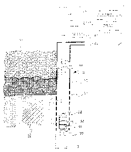
with reservoir parameters of pump depth Xp and pump
length Lp to determine pump suction pressure Pse and
casing fluid level Xce.
[0081] More specifically, the processing unit 54
responds to the value representing pump flow rate Qp.
MW1013131 2 9
CA 02442973 2003-09-26
c
This value representing pump flow rate Qp can be
either the value of Qpe produced by the pump model 60,
as- shown in FLG. 3, or the value of Qpm as shown in
FIG. 4 from a surface flow sensor 59 (FIG. 2) . This
pump flow rate value is used to calculate a tubing
flow head loss estimate Hfe in block 81. The head
loss equation for Hfe presented in block 81 can be
derived empirically and fit to an appropriate equation
or obtained from well known relationships for
incompressible flow: One such relationship for flow
head loss estimate Hfe is obtained from the Darcy-
Weisbach equation
(1) Hfe = f L (L/a) (~12/2G) ~
where f is the friction factor; L is the length of the
tubing, d is the inner diameter of the tubing, V is
the average fluid velocity (Q/A, where Q is the fluid
flow and A is the area of the tubing), and G is the
gravitational constant. For laminar flow conditions
(Re < 2300), the friction factor f is equal to 64/Re,
where Re is ,he Reynolds number. For turbulent flow
conditions, the friction factor can be obtained using
the Moody equation and a modified Colebrook equation,
which will be known to one of ordinary skill in the
art. For non=circular pipes, the hydraulic radius
(diameter) equivalent may be used in place of the
diameter in equation (1). Furthermore, in situ
calibration may be employed to extract values for the
friction factor f in equation (1) by system
identification algorithms. Commercial programs that
account for detailed hydraulic losses within the
tubing are also available for calculation of fluid
flow loss factors.
MW1013131 3 0
CA 02442973 2003-09-26
v
[0082] It should be noted that although fluid
velocity V may change throughout the tubing length,
the value for fluid velocity can be assumed to be
constant over a given range.
[0083] The suction pressure Pse is calculated by
adding the head loss Hfe calculated in block 81 with
the pump depth Xp and subtracting the pump head
pressure Hpe in summing block 82. The output of
summing block 82 is sealed by the tubing fluid
specific weight Dt in block 83 and added to the value
representing tubing pressure Pt in summing block 84 to
yield the suction pressure Pse.
[0084] The pump discharge pressure Pde is
calculated by scaling the length of the pump Lp by the
casing fluid specific weight Dc in block 87. The pump
head pressure Hpe i then scaled by the pump fluid
specific weight Dp in block 88 to yield the
differential pressure across the pump, Ppe. Pump
pressure Ppe is then added to the pump suction
pressure Pse and the negative of the output of sealing
block 87, in summing block 89 to calculate the pump
discharge pressure Pde.
[0085] The casing fluid level Xce is calculated by
subtracting casing pressure Pc from the suction
pressure Pse, calculated in summing block 84, in
summing block 85. The result of summing block 85 is
scaled by the reciprocal of the casing fluid specific
weight Dc in block 86 to yield the casing fluid level
XCe.
[0086] The casing fluid specific weight Dc, pump
fluid specific weight Dp, and tubing fluid specific
weight Dt may differ die to different amounts and
properties of dissolved gases in the fluid. At
reduced pressures, dissolved gases may bubble out of
MW1013131 3 1
CA 02442973 2003-09-26
s
t
' ...-
the fluid and affect the fluid density. Numerous
methods are available for calculation of average fluid
density as a function of fluid and gas properties
which are known in the art.
Fluid Level Feedforward Controller
C0087] Referring to FIG. 8, there is shown a
process diagram' of the fluid level feedforward
controller 90. The fluid level feedforward controller
90 uses flow head loss Hfe; pump head pressure Hre at
rated speed and other parameters to produce a motor
speed feedforward command Umf to be summed with the
motor speed feedback command Ufc in summing block 79
(FTG. 3 and FIG. 4) to produce the motor speed command
Umc for the motor vector controller 130. This speed
signal is based on predicting the pump speed required
to maintain desired pressures, flows and levels in the
pumping system. Use of this controller reduces the
amount of fluid level error in the fluid leve l
feedback controller 100 (FLG. 9), allowing
conservative controller tuning and faster closed loop
system response.
C0088] More specifically, in scaling block 91, the
value of casing pressure Pc is scaled by the inverse
of the casing fluid specific weight Dc to express the
result in equivalent column height (head) of casing
fluid. Similarly, in scaling block 92, the value of
tubing pressure Pt is scaled by the inverse of the
tubing fluid specific weight D to express the result
in equivalent column height (head) of tubing 'fluid.
In summing block 93, the negative of the output of
block 91 is added to the output of block 92, the pipe
head flow loss Hfe; the depth of the pump Xp; and the
negative of the commanded casing fluid level Xcc to
MW1013131 3 2
CA 02442973 2003-09-26
'~,,~,: , . ~~,
obtain pump head pressure command Hpc. The flow head
loss Hfe is the reduction in pressure due to fluid
friction as calculated in block 81 (FIG. 7). The
commanded pump head Hpc is the pressure that the pump
must produce as a result of the inputs to summing
block 93. The values of casing pressure Pc and tubing
pressure Pt can be measured in real time using above
ground sensors in systems where they are variable or
fixed for systems where they are relatively constant.
The values of pump depth Xp and commanded casing fluid
level command Xcc are known.
(0089] More specifically, in block 94, the pump
speed required to produce the pressure required by the
head pressure command Hpc is calculated by multiplying
the rated speed Ur by the square root of the ratio of
the head pressure command Hpc to the head pressure at
rated speed Hre t o yield the motor speed feedforward
command Umf. The value of head pressure at rated
speed Hre is calculated by block 65 of FIG. 5 or block
265 of FLG. 6 depending on the specific embodiment.
Fluid Level Feedback Controller
(0090] Reference is now made to FIG. 9, which is a
block diagram of a fluid level feedback controller 100
2,5 for the motor vector controller 130. The fluid level
feedback controller 100 includes a PID (proportional,
integral, derivative) function that responds to errors
between casing fluid level command Xcc and casing
fluid level Xce to adjust the speed command for the
pump 3~. Operation of the fluid level feedforward
controller 90 provides a command based on the
projected operation of the system: This assures that
the errors to which the fluid level feedback
MW1013131 3 3
CA 02442973 2003-09-26
~.,~; t~
controller 100 must respond will only be the result of
disturbances to the system.
[0091] The inputs to the fluid level feedback
controller 100 include casing fluid level command Xcc
and a casing fluid level value Xce. The fluid level
command Xcc is a known value and is subtracted from
the casing fluid level value Xce in block 101 to
produce the error signal Xer for the fluid level
feedback controller 100.
C0092] The algorithm of the fluid level feedback
controller 100 uses Z-transformations to obtain values
for the discrete PID controller. The term Z-1 (blocks
102 and 109) means tha the value from the previous
iteration is used during the current iteration.
[0093] More specifically, in summing block 101, an
error signal Xer is produced by subtracting Xcc from
Xce. The speed command derivative error term Udc is
calculated by subtracting, in summing block 103, the
current Xer value obtained in block 101 from the
previous Xer term obtained from block 102 and
multiplying by the'derivative gain Kd in block 104.
The speed command proportional error term Upc is
calculated by multiplying the proportional gain Kp in
block 105 by the current Xer value obtained in block
101. The speed command integral error term Uic is
calculated by multiplying the integral gain Ki in
block 106 by the current Xer value obtained in block
101 and summing this value in block 107 with the
previous value of Uic obtained from block 109. The
output of summing block 107 is passed through an
output limiter, block 108, to produce the current
integral error term Uic. The three error terms, Udc,
Upc and Uic, are combined in summing block 110 to
produce the speed command Ufc to be summed with the
MW1013131
~ 02442973 2003-09-26
l..wi
motor speed feedforward command Umf in summing block
79 (FIG. 3 and FIG: 4) for the motor vector controller
130.
Vector Controller
[0094 Reference is now made to FIG. 10, which is a
simplified block diagram of the motor vector
controller 130. The motor vector controller 130
contains functions for calculating the velocity error
and the torque necessary to~correct it, convert torque
commands to motor voltage commands and current
commands and calculate motor torque and speed
estimates from measured values of motor voltages and
motor currents.
[0095 In one embodiment, the stator flux is
calculated from motor voltages and currents and the
electromagnetic torque is directly estimated from the
stator flux and stator current. More specifically; in
block 131, three-phase motor voltage measurements Vmm
and current measurements Imm are converted to dq
(direct/quadrature) frame signals using three to two
phase conversion for ease of computation in a manner
known in the art. Signals in the dq frame can be
represented as individual signals or as vectors for
convenience: The' motor vector feedback model 132
responds to motor stator voltage vector Vs and motor
stator current vector Is to calculate a measure of
electrical torque Tme produced by the motor. In one
embodiment, the operations carried out by motor vector
feedback model 132 for calculating the electrical
torque estimate are as follows. The stator flux vector
Fs is obtained from the motor stator voltage Vs and
motor stator current Is vectors according to equation.
(2)
MW1013131 3 5
CA 02442973 2003-09-26
(2) Fs _ (Vs-Is.Rs)/s
(2A) Fds = (Vds-Ld .Rs) /s
(2B) Fqs _ (Vqs-+Lqs.Rs)/s
where Rs is the stator resistance and s (in the
denominator) is the Laplace operator for
differentiation. Equations (2A) and (2B) show typical
examples of the relationship between the vector
l0 notation for flux Fs, voltage Vs, and current Is and
actual d axis and q axis signals.
[0096] In one embodiment; the electrical torque Tme
is estimated directly from the stator flux vector Fs
obtained from equation (2) and the measured stator
current vector Is according to equation (3) or its
equivalent (3A)
(3) Tme = Ku:(3/2).P.Fsxls
(3A) Tme = Ku. (3/2) .P. (Fds.Lqs-Fqs.Zds)
where P is the number of motor pole pairs and Ku is a
unit scale factor to get from MKS units to desired
units.
[0097] In one embodiment, rotor velocity Ume is
obtained from estimates of electrical frequency Ue and
slip frequency Us. The motor vector feedback model
132 also performs this calculation using the stator
voltage Vs and stator current Is vectors. In one
embodiment, the operations carried out by the motor
vector feedback model 132 for calculating the motor
velocity Ume are as follows: A rotor-flux vector Fr
is obtained from the measured stator voltage Vs and
stator current Is vectors along with motor stator
resistance Rs, stator inductance Ls, magnetizing
MW1013131 3 6
CA 02442973 2003-09-26
inductance Lm, leakage inductance SigmaLs, and rotor
inductance Lr according to equations (4) and (5);
separate d axis and q axis rotor flux calculations are
shown in equations (5A) and (5B) respectively:
(4) SigmaLs _ Ls-Lm~2/Lr
then;
(5) Fr = (Lr/Lm).[Fs-Is.SigmaLs]
(5A) Fdr = (Lr/Lm).(Fds-SigmaLs.Ids)
(5B) Fqr = (Lr/Lm) . (Fqs-SigmaLs.Iqs)
[0098] The slip frequency Us can be derived from
the rotor flux vector Fr; the stator current vector
Is, magnetizing inductance Lm, rotor inductance Lr,
and rotor resistance Rr according to equation (6):
(6) Us = Rr.(Lm/Lr).jFdr.Iqs-Fqr.Ids]
Fdr"2+Fqr~2
[0099] The instantaneous excitation or electrical
frequency Ue can be derived from stator flux
according to equation (7):
(7) Ue = Fds.sFqs-Fqs.sFds
Fds"2+Fqs~2
[0100] The rotor velocity or motor velocity Ume can
be derived from the number of motor pole pairs P the
slip frequency Us and the electrical frequency Ue
according to equation (8):
(8) Ume = (Ue-Us) (60) /P
Mwio13z3i 3 7
CA 02442973 2003-09-26
. ~' \
[0101] Tn cases where long cable lengths or step up
transformers are used, the impedances of the
additional components Can be added to the model of
motor impedances in a method that is known.
[0102] The velocity controller 133 uses a PI
controller (proportional, integral), PID controller
(proportional, integral, derivative) or the like to
compare the motor. speed Ume with the motor speed
command Umc and produce a speed error torque command
Tuc calculated to eliminate the speed error.' The
speed error torque command Tuc is then converted to
motor current commands Imc and voltage commands Vmc in
flux vector controller 134 using a method which is
known.
[0103] Refe~ririg to FIG. 15, in one preferred
embodiment, the pump control system provided by the
present invention is software based and is capable of
being executed in a controller 50 ,shown in block
diagram form in FIG: 13. In one embodiment, the
controller 50 includes current sen ors 5l, voltage
sensors 52, input devices 171, such as analog to
digital converters, output devices 172, and a
processing unit 54 having associated random access
memory (RAM) and read-only memory (ROM). In one
embodiment, the s orage devices 55 include a database
175 and software programs and files which are used in
carrying out simulations of circui s and/or systems in
accordance with the invention. The programs and files
of the controller 50 include an operating system 176,
the parameter estimation engines 177 that includes the
algorithms for the pump model 60 (FIG. 5) or pump
model 260 (FIG. 6:) arid the pump system model 80 (FIG.
7), pump controller engines 178 that include the
algorithms for fluid level feedforward Controller 90
MW1013131 3 8
CA 02442973 2003-09-26
(FIG. 8) and the fluid level feedback controller 100
(FIG. 9), and vector controller engines 179 for the
motor vector controller 130 for converting motor
current and voltage measurements to torque and speed
estimates and converting speed and torque feedforward
commands to motor current and voltage commands; for
example. The programs and files of the computer
system can also include or'provide storage for data.
The processirig unit 54 is connected through suitable
input/output interfaces and internal peripheral
interfaces (not shown) ~to the input devices, the
output devices, the storage devices, etc., as is
known.
Optimized Gas Production
[0104] The production of methane gas from coal
seams can be optimized using the estimated parameters
obtained by the pump controller 50 (FIG. 3 or FIG. 4)
in accordance with the invention. For methane gas
production, it is desirable to maintain the 'casing
fluid level .at an optimum level . A range for casing
fluid level command Xcc is selected to define an
optimal casing fluid level for extracting methane gas.
This range is commonly referred to as a sweet zone.
[01U5] In one embodiment of the present invention,
the selection of the sweet zone is determined by the
controller 50 {FIG. 3 or FIG. 4) that searches to find
the optimum casing fluid level command Xcc. Since the
sweet zone can change as conditions in the well change
over time, it can be advantageous to program the
controller 50 to:perform these :searches at periodic
intervals or when specific conditions, such as a
decrease in efficiency; are detected. In determining
the sweet zone, the centrifugal pump intake pressure
MW1013131 3 f
CA 02442973 2003-09-26
Ps or casing fluid level Xc is controlled The
centrifugal pump 32 is controlled by the fluid level
feedforward controller 90 and the fluid level feedback
controller 100 to cause the casing fluid level Xc to
be adjusted until maximum'gas production is obtained.
The casing fluid level command Xcc is set to a
predetermined start value. The methane gas flow
through outlet 42 at the surface is measured. The
casing fluid level command is then reputedly
incremented to progressively lower values. The
methane gas production is measured at each'new level
to determine the value of. casing fluid level Xc at
which maximum gas production is obtained. The point
of optimum performance is called the sweet spot. The
1'5 sweet zone is the range of casing fluid level above
and below the sweet. spot within which the gas
production decrease is acceptable.However, the
selection of the sweet zone can be done manually by
taking readings.
Improved Pump Energy Efficien ~ and Operating Range
[0106 One method to optimize the pump control when
operated at low flow and/or efficiency, is to operate
using a duty cycle mode to produce the required
average flow rate while still operating the
centrifugal pump at its most efficient and optimal
flow rate point Qo: In this duty cycle mode, the
volume of fluid to be removed from the casing can be
determined using the fluid inflow rate Qi when the
casing fluid level Xc is near the desired level. A
fluid level tolerance band is defined around the
desired fluid level, within which the fluid level is
allowed to vary: The wlume vb of the fluid level
tolerance band is calculated from the projected area
Mwnoiaiai 4 0
CA 02442973 2003-09-26
between the tubing; casing and pump body and the
prescribed length of the tolerance band. This volume
is used with the fluid inflow rate Qi to determine the
pump off time period Toff. When the centrifugal pump
is on, the value ;for casing fluid level Xc is
calculated and the fluid letrel in the casing is
reduced to the lower level of the fluid level
tolerance band, when the pump is again turned off.
The fluid inflow rate Qi is calculated by dividing the
fluid level tolerance band volume Vb by the on time
period Ton used to: empty the band, then subtracting
the result from the optimal pump flow rate Qo used'to
empty the band. The on-off duty cycle varies
automatically to adjust for changing well inflow
characteristics. This variable duty cycle continues
with the centrifugal pump operating at its maximum
efficiency over a range of average pump flow rates
-irarying from almost zero to the f low associated with
full time operation at he most efficient speed. Use
of the duty c~rcla ; mode also increases the range of
controllable pump average flow by using the ratio of
on time, Ton, multiplied by optimal flow rate, Qo,
divided by total cycle time (Ton -i- Toff) rather than
the centrifugal pump speed to adjust. average flow.
Thus also avoids the problem of erratic flow
associated with operating the pump at very low speeds.
This duty cycle method can produce significant energy
savings at reduced average flow rates as shown in FIG.
16. As can be seen in FIG. 16, the efficiency of the
example pump using continuous operation decreases
rapidly below about 7.5 gallons per minute (GPM),
while the efficiency of the same pump operated using
the duty cycle method .remains at near optimum
efficiency over the full range of average flow.
Mw1o1313i 4 1
CA 02442973 2003-09-26
.... ' W ..-../
Coio~] Pump system efficiency is determined by the
ratio of the fluid power output to the mechanical or
electrical power input. When operated to maximize
efficiency, the controller turns the centrifugal pump
off when the centrifugal pump starts operating in an
inefficient range: Ln addition, the centrifugal pump
is turned off if a pump off condition casing .level at
the pump intake is' detected by a loss of measured
flow.
[U108] For systems with widely varying flow
demands, multiple centrifugal pumps, each driven by a
separate motor, may be connected in parallel and
staged (added or shed) to supply the required capacity
and to maximize overall efficiency. The decision for
staging multiple centrifugal pumps is generally based
on the maximum operating efficiency or capacity of the
Centrifugal pump or combination of centrifugal pumps.
As such, when a system of centrifugal pumps is
operating beyond its maximum efficiency point or
capacity and'another centrifugal pump is available, a
centrifugal pump is added when the efficiency of the
new combination of centrifugal pumps exceeds the
current operating efficiency. Conversely, when
multiple centrifugal pumps are operating in parallel
and the flow is below the combined maximum efficiency
point, a centrifuges-l pump is shed when the resulting
combination of centrifugal pumps have a better
efficiency. These cross-over points can be calculated
directly from the efficiency data for each centrifugal
3o pump in the system , whether the additional centrifugal
pumps are variable speed or fixed speed:
MW7.013131 t~2
CA 02442973 2003-09-26
.. 'y,
Pump and Pump System Protection
001097 One method of projecting the cent rifugal
pump and system components is to use sensors to
measure the perforrriance of the system above ground and
compare this measurement to a calculated performance
value. If the two values differ by a threshold amount ,
a fault sequence is initiated which may include such
steps as. activating an audio or visual alarm for the
operator, activating an alarm signal to a separate
supervisory controller or turning off the centrifugal
pump . In one embodiment , a sensor i s used to measure
the flow in the tubing at the surface Qpm and compare
it with the calculated value Qpe. If the actual flow
Qpm is too low relative to the calculated flow Qpe,
this could be an indication of a fault such as a
tubing leak, where not all of the flow through the
centrifugal pump is getting to the measurement point.
C0110~ Another method of protecting the pump is to
prevent excessive mechanical power input. In one
embodiment, the mechanical power input to the pump.is
calculated by multiplying the speed Ume by the torque
Tme. The result is compared to the mechanical input
power limit P1e calculated by the pump model (FIG. 5
or FIG. 6). I~ the Limit Ple is exceeded, the torque
and speed are reduced to protect the pump.
0017.1] Although exemplary embodiments of the
present invention have been shown and described with
reference to particular embodiments and applications
thereof; it will be: apparent to those having ordinary
skill in the art that a number of changes,
modifications, or alterations to the invention as
described herein may be made, none of which depart
from the spirit or,scope of the present invention.
rnaioiaisi 43
CA 02442973 2003-09-26
l
All such changes, modifications, and alterations
should therefore be seen as being within the scope of
the present invention.
MN11013131 ~ 4