Language selection

Search

Patent 2443822 Summary

Third-party information liability

Some of the information on this Web page has been provided by external sources. The Government of Canada is not responsible for the accuracy, reliability or currency of the information supplied by external sources. Users wishing to rely upon this information should consult directly with the source of the information. Content provided by external sources is not subject to official languages, privacy and accessibility requirements.

Claims and Abstract availability

Any discrepancies in the text and image of the Claims and Abstract are due to differing posting times. Text of the Claims and Abstract are posted:

  • At the time the application is open to public inspection;
  • At the time of issue of the patent (grant).
(12) Patent: (11) CA 2443822
(54) English Title: SPLIT GRIP CONTROL LEVER FOR HEAVY MACHINERY
(54) French Title: LEVIER DE COMMANDE A POIGNEE DIVISEE POUR MACHINERIE LOURDE
Status: Term Expired - Post Grant Beyond Limit
Bibliographic Data
(51) International Patent Classification (IPC):
  • G05G 9/047 (2006.01)
  • E02F 9/20 (2006.01)
  • G05G 1/06 (2006.01)
  • G05G 1/10 (2006.01)
(72) Inventors :
  • BLACK, PHILLIP JOHN (United States of America)
(73) Owners :
  • JLG INDUSTRIES, INC.
(71) Applicants :
  • JLG INDUSTRIES, INC. (United States of America)
(74) Agent: SMART & BIGGAR LP
(74) Associate agent:
(45) Issued: 2006-09-05
(86) PCT Filing Date: 2002-02-05
(87) Open to Public Inspection: 2002-11-07
Examination requested: 2003-11-24
Availability of licence: N/A
Dedicated to the Public: N/A
(25) Language of filing: English

Patent Cooperation Treaty (PCT): Yes
(86) PCT Filing Number: PCT/US2002/003205
(87) International Publication Number: WO 2002088865
(85) National Entry: 2003-10-09

(30) Application Priority Data:
Application No. Country/Territory Date
09/842,028 (United States of America) 2001-04-26

Abstracts

English Abstract


A split grip control lever (10) is suitable for operating heavy machinery and
includes a fixed base portion (12) that provides secure operator support
during operation of the machine. A movable upper portion (16) is pivotable
relative to the fixed base portion by the user's thumb and index finger to
control operation of machine components. The movable upper portion and the
fixed base portion preferably define a substantially continuous profile.
Additionally, a control device (24) is placed inside the fixed base portion of
the grip, allowing for a shorter control shaft that pivots at or near the
center of the unit. This arrangement facilitates control of the equipment.


French Abstract

L'invention concerne un levier de commande à poignée divisée (10) destiné à la mise en oeuvre d'une machinerie lourde et comprenant une partie de base fixe (12) offrant un support ferme à l'opérateur pendant le fonctionnement d'une machine. Une partie supérieure mobile (16) peut pivoter par rapport à la partie de base fixe sous l'action du pouce et de l'index de l'utilisateur en vue de commander le fonctionnement des composants de la machine. De préférence, la partie supérieure mobile et la partie de base fixe présentent un profil sensiblement continu. Par ailleurs, un dispositif de commande (24) est placé à l'intérieur de la partie de base fixe de la poignée, ce qui permet d'utiliser un arbre de commande plus court qui pivote au niveau ou au voisinage du centre de l'unité. Cet agencement facilite la commande de l'équipement.

Claims

Note: Claims are shown in the official language in which they were submitted.

5
WHAT IS CLAIMED IS:
1. A split grip control lever comprising:
a fixed base portion (12);
a movable upper portion (16), characterized in that the movable upper portion
is separately
pivotable relative to the fixed base portion, and that the movable upper
portion and the fixed
base portion define a substantially continuous profile; and
a control device (24) positioned within the fixed base portion (12), wherein
the movable
upper portion (16) comprises a control shaft (26) coupled with the control
device.
2. A split grip control lever according to claim 1, wherein the control device
(24)
is disposed at a substantially central position relative to the lever profile
such that a pivot point
of the control shaft (26) is centrally disposed relative to the lever profile.
3. A split grip control lever according to claim 1, wherein the fixed base
portion
(12) is fixedly securable to a surface (14), and wherein the control device
(24) is disposed at a
position spaced from the surface at a substantially central position relative
to the lever profile.
4. A split gip control lever according to claim 1, wherein the control device
(24)
is an electromechanical control device.
5. A split grip control lever according to claim 1, wherein the control device
(24)
is an optical control device.
6. A split grip control lever according to claim 1, wherein the substantially
continuous profile is shaped to fit an operator's hand.
7. A split grip control lever according to claim 6, wherein the substantially
continuous profile is shaped to fit one of an operator's right hand or left
hand.
8. A split grip control lever according to claim 1, wherein the movable upper
portion (16) is disposed relative to the fixed base portion (12) and sized for
manipulation by an

6
operator's thumb and index finger, and wherein the fixed base portion is
disposed relative to
the movable upper portion and sized to support the operator's hand.
9. A control lever for machinery comprising:
a fixed based portion (12) fixedly securable to a surface (14) of the
machinery;
a control portion (16, 24, 26) including a movable upper portion disposed
adjacent the
fixed base portion and movable relative to the fixed base portion,
characterized in that the
movable upper portion is separately pivotable relative to the fixed base
portion and that the
control portion is contiguous with the fixed base portion to define a
substantially continuous
profile; and
a control device (24) positioned within the fixed base portion (12), wherein
the control
portion comprises a control shaft (26) coupled with the control device.
10. A control lever according to claim 9, wherein the control device (24) is
disposed
at a substantially central position relative to the lever profile such that a
pivot point of the
control shaft (26) is centrally disposed relative to the lover profile.
11. A control lever according to claim 9, wherein the control device (24) is
disposed
at a position spaced from the surface (14) at a substantially central position
relative to the lever
profile.
12. A machine comprising:
a machine frame (14) supporting at least one movable element; and
a control lever (10) secured to the machine frame, the control lever
comprising:
a fixed base portion (12) fixedly secured to the machine frame,
a movable upper portion (16), characterized in that the movable upper portion
is
separately pivotable relative to the fixed base portion for controlling
movement of the at least
one movable element, and that the movable upper portion and the fixed base
portion define a
substantially continuous profile, and
a control device (24) positioned within the fixed base portion (12), and
wherein the
movable upper portion (16) comprises a control shaft (26) coupled with the
control device.

7
13. A machine according to claim 12, wherein the control device (24) is
disposed at
a substantially central position relative to the lever profile such that a
pivot point of the control
shaft (26) is centrally disposed relative to the lever profile.
14. A machine according to claim 12, wherein the control device (24) is
disposed at
a position spaced from the machine frame (14) at a substantially central
position relative to the
lever profile.

Description

Note: Descriptions are shown in the official language in which they were submitted.


CA 02443822 2003-10-09
WO 02/088865 PCT/US02/03205
SPLIT GRIP CONTROL LEVER FOR HEAVY MACHINERY
BACKGROUND AND SUMMARY OF THE INVENTION
The present invention relates to a control lever for heavy machinery and, more
particularly, to a control lever including a fixed grip portion to help
support an operator while
driving or maneuvering the machinery, while reducing the potential for
inadvertent motion of
the control during operation.
Many types of equipment place an operator in a position where the operator
moves with
an arm or other device attached to the machine. The operator may be standing
or sitting while
maneuvering the equipment. As such, from this position, the operator must
attempt to
counteract the inertia forces associated with motion and operation of the
machinery.
Because of these forces, it is desirable for manufacturers to provide a fixed
grip for the
operator that also contains the controls necessary to move or position parts
of the equipment.
Such a design would help address issues associated with operator comfort,
safety and support
while operating the equipment.
Current joy stick and control designs do not address the sudden inertia shifts
which may
or may not occur as a result of the operator's decision to activate or cease
activation of a
moving function of the machine to which the operator is part of the movement.
In addition,
current designs force the operator to grasp a control lever that pivots at or
near the base of the
hand. These designs do not offer adequate fixed support for the operator and
may cause
sudden inadvertent movement of the equipment.
With the split grip control lever according to the present invention,
inadvertent motion
caused by inertia shifts in the operator's environment can be substantially
eliminated. The grip
includes a movable control portion that is operated by the thumb and index
finger and a fixed
portion that serves to support the operator's hand. This construction enables
the operator to let
go of the top movable portion of the control lever while maintaining a firm
grasp of the fixed
base portion of the grip.
In an exemplary embodiment of the invention, a split grip control lever
includes a fixed
base portion and a movable upper portion that is separately pivotable relative
to the fixed base
portion. The movable upper portion and the fixed base portion define a
substantially
continuous profile. A control device is positioned within the fixed base
portion, and the
movable upper portion includes a control shaft coupled with the control
device. Preferably, the

CA 02443822 2003-10-09
04'fl'4'~OS Ut'''J~2L1~20S
2
control device is disposed at a substantiaDy ccntTal position relative to the
k~ ~ such
that a pivot point of the control shaft is centrally disposed relative to the
lever profile: in other
words, the control device is disposed at a position spacod from a surface to
which the fixed
base portion is fixedly secured at a substantially central position relative
to the levy profile.
The control device may be an elsxtromechanical conaol device or an
opticahcontrol device.
The substantially continuous profile is preferably shaped to fit a user's
hand. In his
context, the profile may be configured for a user's night hand or a user's
left hand. As noted
above, the movable upper portion is disposed relative to the fixed base
portion and sued for
manipulation by a user's thumb and index finger, while the fixed base portion
is disposed
relative to the movable upper portion and sized to support the user's hand
In another exemplary embodiment of the invention, a convol lever for machinery
includes a fixed base partion fixedly securable to a surface of the machinery,
and a~control
portion disposed adjacent the fixed base portion and movable relative to the
fixed base portion.
The control portion is separated from the fixed base portion via a split line
and is contiguous
with the fixed base portion to define a substantially continuous profile.
In yet another exemplary embodiment of the invention, a machine including a
machine
frame supporting at least one movable element is provided with the control
lever of the present
invention.
BRIEF DESCRIPTION OF THE DRAWINGS
These and other aspects and advantages of the present invention will be
described in
detail with reference to the accompanying drawings, in which:
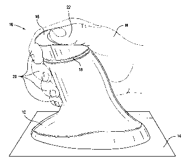
FIGURE 1 is a perspecrive view of the split grip control lever;
FIGURE 2 is an internal schematic illustration of the split grip control lever
shown in
FIGURE 1: and
FIGURE 3 is a sectional view through the control lever control shaft.
DETAILED DESCRIPTION OF PREFERRED EMBODIMENTS
A~ shown in F1GURE 1. the split grip control lever 10 of the present invention
includes
a fixed base portion 12 that is fixedl~l securable to a surface 14 such as a
machine frame,
control panel or the like, and a movable upper portion 1b defining a control
portion of the lever
that is movable relative to the fixed base portion 12. The movable upper
portion l6 and the
fixed base portion 12 are essentially contiguous but separated by a split line
78. With this
AMENDED SHEET

CA 02443822 2003-10-09
04 t~-2003 U'S02032(~
3
construction, the movable upper portion 16 and the fined base portion 12
togetherdafine a
substantially continuous ale as shown in FIGURE 1.
The continuous profile is preferably shaped to fit a user's hand Hand includes
finger
grip portions 20 and a thumb grip portion 22. The grip shown in FIGURE 1 is
configured for
3 right hand operation, although an advantageous embodiment of the invention
enables the
pmfile to be configured for kft hand operation or custom configured for a
particular user's
hand size or the like. 3'he ~p is preferably formed of a suitable engineered
plastic, although
other suitably formable materials may be used. As shown, the movable upper
portion i~6 is
disposed relative to the fixed base portion 12 and sized for manipulation by
an operator's
l0 thumb and index finger, while the fixed base portion 12 is disposed
relative to the movable
upper portion 16 and sized to .support the operator's hand.
FIGURE 2 is a schematic illustration of the operating components within the
split grip
control lever, and FIGURE 3 is a sectional view through the lever. Any
suitable multi-position
pivoting control switch, such as an electromechanical or optical control
switch, can be
i~ implemented into the split grip control lever, and a detai3ed description
of the control
components is omitted. That is, any known system that generates a control
signal based on
movement of a control lever to effect machine operation could be used.
In the present invention, however, a control device 24 is preferably
positioned within
the fixed base portion 12 as shown in FIGURE 2, and the movable upper portion
16 includes a
20 control shaft 26 coupled with the control device 24 at a substantially
central position relative to
the lever profile such that a pivot point 28 of the control shaft 26 is
centrally disposed relative
to the lever profile. That is, with the fixed base portion 12 secured to a
machine frame, surface
or the like 14, the control device 24 is disposed at a position spaced from
the surface i4 at a
substantially central position relative to the lever profile. Such positioning
allows for a short
25 control shaft 26 which pivots at or near the center of the unit. By this
arrangement, finite
control of the equipment is readily effected, which contrasts many existing
control lever
designs that require longer movements of the control lever to maintain
proportional movement
of the equipment. The control device 24 also includes a boot 30 that protects
the control
device components and a sealed bulkhead 32 that helps secure the control
device 24 and seal
30 the boot 30.
The lever may additionally be provided with a capacitance proximity sensor 34,
such as
the QProx QT sensor available from Quantum Research Group in the t.'~nited
Kingdom, which
detects the presence of a human hand and only activates the lever upon such a
detection. The
AMENDED'SHEET

CA 02443822 2005-12-16
4
sensor 34 thus serves to prevent inadvertent activation of machine
components. A control lever incorporating a capacitance sensor is described
in commonly-owned U. S. Patent No. 6,501,198. Alternatively, the lever may
be provided with a conventional mechanical safety trigger lock or the like.
With the construction of the present split grip control lever, the
ergonomic shape of the lever as it relates to various hand sizes, right and
left
hand specific orientation, etc., contributes to the effectiveness of the
design.
The arrangement invites the operator's hand to a relaxed position and allows
for full movement of the controls with minimal stress or fatigue to the hand.
As
a consequence, the overall feel of the control is optimized while enabling an
operator to avoid inadvertent movement and actuation of machine
components by grasping the fixed base portion.

Representative Drawing
A single figure which represents the drawing illustrating the invention.
Administrative Status

2024-08-01:As part of the Next Generation Patents (NGP) transition, the Canadian Patents Database (CPD) now contains a more detailed Event History, which replicates the Event Log of our new back-office solution.

Please note that "Inactive:" events refers to events no longer in use in our new back-office solution.

For a clearer understanding of the status of the application/patent presented on this page, the site Disclaimer , as well as the definitions for Patent , Event History , Maintenance Fee  and Payment History  should be consulted.

Event History

Description Date
Inactive: Expired (new Act pat) 2022-02-07
Common Representative Appointed 2019-10-30
Grant by Issuance 2006-09-05
Inactive: Cover page published 2006-09-04
Inactive: Final fee received 2006-06-19
Pre-grant 2006-06-19
Notice of Allowance is Issued 2006-04-03
Letter Sent 2006-04-03
Notice of Allowance is Issued 2006-04-03
Inactive: IPC from MCD 2006-03-12
Inactive: Approved for allowance (AFA) 2006-01-30
Amendment Received - Voluntary Amendment 2005-12-16
Inactive: S.30(2) Rules - Examiner requisition 2005-09-19
Letter Sent 2004-01-07
Amendment Received - Voluntary Amendment 2004-01-06
Inactive: Cover page published 2003-12-16
Inactive: Notice - National entry - No RFE 2003-12-12
Letter Sent 2003-12-12
Request for Examination Received 2003-11-24
Request for Examination Requirements Determined Compliant 2003-11-24
All Requirements for Examination Determined Compliant 2003-11-24
Application Received - PCT 2003-10-31
National Entry Requirements Determined Compliant 2003-10-09
Application Published (Open to Public Inspection) 2002-11-07

Abandonment History

There is no abandonment history.

Maintenance Fee

The last payment was received on 2006-02-01

Note : If the full payment has not been received on or before the date indicated, a further fee may be required which may be one of the following

  • the reinstatement fee;
  • the late payment fee; or
  • additional fee to reverse deemed expiry.

Please refer to the CIPO Patent Fees web page to see all current fee amounts.

Owners on Record

Note: Records showing the ownership history in alphabetical order.

Current Owners on Record
JLG INDUSTRIES, INC.
Past Owners on Record
PHILLIP JOHN BLACK
Past Owners that do not appear in the "Owners on Record" listing will appear in other documentation within the application.
Documents

To view selected files, please enter reCAPTCHA code :


To view images, click a link in the Document Description column. To download the documents, select one or more checkboxes in the first column and then click the "Download Selected in PDF format (Zip Archive)" or the "Download Selected as Single PDF" button.

List of published and non-published patent-specific documents on the CPD .

If you have any difficulty accessing content, you can call the Client Service Centre at 1-866-997-1936 or send them an e-mail at CIPO Client Service Centre.


Document
Description 
Date
(yyyy-mm-dd) 
Number of pages   Size of Image (KB) 
Description 2003-10-09 4 216
Claims 2003-10-09 3 109
Abstract 2003-10-09 1 56
Drawings 2003-10-09 2 42
Representative drawing 2003-10-09 1 15
Cover Page 2003-12-16 2 43
Drawings 2005-12-16 2 39
Description 2005-12-16 4 215
Representative drawing 2006-08-08 1 10
Cover Page 2006-08-08 1 42
Acknowledgement of Request for Examination 2004-01-07 1 188
Notice of National Entry 2003-12-12 1 203
Courtesy - Certificate of registration (related document(s)) 2003-12-12 1 125
Commissioner's Notice - Application Found Allowable 2006-04-03 1 162
PCT 2003-10-09 14 575
Correspondence 2006-06-19 1 36