Language selection

Search

Patent 2444753 Summary

Third-party information liability

Some of the information on this Web page has been provided by external sources. The Government of Canada is not responsible for the accuracy, reliability or currency of the information supplied by external sources. Users wishing to rely upon this information should consult directly with the source of the information. Content provided by external sources is not subject to official languages, privacy and accessibility requirements.

Claims and Abstract availability

Any discrepancies in the text and image of the Claims and Abstract are due to differing posting times. Text of the Claims and Abstract are posted:

  • At the time the application is open to public inspection;
  • At the time of issue of the patent (grant).
(12) Patent Application: (11) CA 2444753
(54) English Title: PRE-FABRICATED LAMINATED WOOD ELEMENT
(54) French Title: ELEMENT DE BOIS STRATIFIE PREFABRIQUE
Status: Deemed Abandoned and Beyond the Period of Reinstatement - Pending Response to Notice of Disregarded Communication
Bibliographic Data
Abstracts

English Abstract


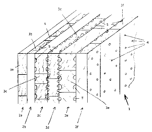
The invention relates to a pre-fabricated laminated wood element comprising at
least three layers (2a, 2b, 2c, 2d, 2e, 2f) of adjacent plank or stanchion-
type wooden elements (3a, 3b, 3c, 3d, 3e, 3f) that are connected to one
another. Said connection is achieved by dowels (4), which penetrate the layers
(2a, 2b, 2c, 2d, 2e, 2f) of wooden elements (3a, 3b, 3c, 3d, 3e, 3f), whereby
the wooden elements (3a, 3b, 3c, 3d, 3e, 3f) of at least two neighbouring
layers (2a, 2b, 2c, 2d, 2e, 2f) run in a different direction. The wooden
elements (3a, 3b, 3c, 3d, 3e, 3f) on the interior surfaces of the laminated
wood element are at least partially profiled, which permits improved thermal
insulation.


French Abstract

L'invention concerne un élément de bois stratifié préfabriqué comprenant au moins trois couches liées entre elles (2a, 2b, 2c, 2d, 2e, 2f) d'éléments en bois du type poteau ou planche directement adjacents (3a, 3b, 3c, 3d, 3e, 3f), dont la jonction s'effectue au moyen de chevilles (4) qui traversent les couches (2a, 2b, 2c, 2d, 2e, 2f) d'éléments en bois (3a, 3b, 3c, 3d, 3e, 3f), les éléments en bois (3a, 3b, 3c, 3d, 3e, 3f) d'au moins deux couches voisines (2a, 2b, 2c, 2d, 2e, 2f) s'étendant dans des directions différentes. Une isolation thermique améliorée est obtenue grâce au fait que les éléments en bois (3a, 3b, 3c, 3d, 3e, 3f) sont au moins partiellement profilés sur les surfaces se trouvant à l'intérieur de l'élément en bois stratifié.

Claims

Note: Claims are shown in the official language in which they were submitted.

-6-
CLAIMS
1. A prefabricated laminated wood element comprising at least three
mutually connected layers (2a, 2b, 2c, 2d, 2e, 2f) of plank- or stanchion-
type wood elements (3a, 3b, 3c, 3d, 3e, 3f) which are arranged directly
adjacent to each other, with the wood elements (3a, 3b, 3c, 3d, 3e, 3f) of
at least two adjacent layers (2a, 2b, 2c, 2d, 2e, 2f) having different
directions, with the wood elements (3a, 3b, 3c, 3d, 3e, 3f) having a
profiling at least partially on the surfaces situated in the interior of the
laminated wood element, characterized in that the connection of the wood
elements (3a, 3b, 3c, 3d, 3e, 3f) occurs by dowels (4) which penetrate the
layers (2a, 2b, 2c, 2d, 2e, 2f) of wood elements (3a, 3b, 3c, 3d, 3e, 3f).
2. A laminated wood element according to claim 1, characterized in that the
profiling is configured as an arrangement of adjacently situated grooves (5)
extending in the longitudinal direction.
3. A laminated wood element according to one of the claims 1 or 2,
characterized in that at least two adjacent layers (2a, 2b, 2c, 2d, 2e, 2f) of
wood elements (3a, 3b, 3c, 3d, 3e, 3f) are provide whose contacting
surfaces comprise grooves which are arranged at an angle with respect to
each other.
4. A laminated wood element according to one of the claims 2 or 3,
characterized in that webs (7) are provided between the grooves (5)
whose width (b) is smaller than that of the grooves (5), with the width (b)
of the webs (7) preferably being between 20% and 80% of the width (c)
of the grooves (5).
5. A laminated wood element according to one of the claims 2 to 4,
characterized in that the edge region of the laminated wood element is
free from grooves (5).
6. A laminated wood element according to one of the claims 1 to 4,
characterized in that at least two adjacent layers (2a, 2b, 2c, 2d, 2e, 2f) of
wood elements (3a, 3b, 3c, 3d, 3e, 3f) are provided whose longitudinal

-7-
axes are arranged at an angle with respect to each other and whose
contacting surfaces are both profiled.
7. A laminated wood element according to one of the claims 1 to 5,
characterized in that at least one layer comprises a groove-like recess,
with the recess being preferably formed by cutting or excavating adjacent
wood elements.
8. A laminated wood element according to one of the claims 1 to 6,
characterized in that the dowels (4) are arranged in a raster-like manner.
9. A laminated wood element according to one of the claims 1 to 7,
characterized in that the connection between the dowels (4) and the wood
elements (3a, 3b, 3c, 3d, 3e, 3f) occurs substantially by frictional
connection due to increase in volume by humidity exchange between the
wood elements (3a, 3b, 3c, 3d, 3e, 3f) of the layers (2a, 2b, 2c, 2d, 2e, 2f)
and the dowels (4).
10. A laminated wood element according to one of the claims 1 to 8,
characterized in that the laminated wood element (1) is made of one
single material and only consists of wood.
11. A laminated wood element according to one of the claims 1 to 9,
characterized in that the laminated wood element (1) comprises at least
two layers (2a, 2b, 2c, 2d, 2e, 2f) which are mutually perpendicular and at
least one layer (2d) which is arranged relative to the same at an acute
angle.

Description

Note: Descriptions are shown in the official language in which they were submitted.


CA 02444753 2003-10-20
10841
A pre-fabricated laminated wood element
The invention relates to a prefabricated laminated wood element according to
the
preamble of claim 1.
It is known to compose wood elements of several layers of boards. Individual
boards may be provided with a profiling in order to reduce the weight, create
hollow spaces for installing items or improve heat insulation. Such composite
materials are usually fastened by gluing, which on the one hand leads to a
deterioration in the heat insulation properties when the glue seeps into the
grooves of the profiling or even fills the same, and on the other hand such
composite materials pose problems in recycling.
From WO 00/03850 A of the applicant a prefabricated laminated wood element is
known which consists of several layers of wood which are mutually connected by
way of dowels. The advantage of such a laminated wood element is that walls
can be thus produced which are made of biologically produced material without
any chemical bonding agents, nails or the like. These walls are characterized
by
favorable static properties and favorable heat insulation. Furthermore, such
laminated wood elements have a very high resistance to fires and an
outstanding
screening against high-frequency electric fields.
Furthermore, from DE 297 21 848 U a wooden wall is known which is composed
of several layers of boards which are connected with each other by means of
nailing. In order to reduce the production costs the boards are provided in
the
interior so as to be rough from sawing.
It is the object of the present invention to provide a wall element which is
completely made up of biological material and that allows a further
improvement
in heat insulation.
This object is achieved in accordance with the invention by the arrangement
according to claim 1.
It has been seen that an additional improvement in the heat insulation
properties
can be achieved by the arrangement in accordance with the invention without
any impairment to the strength. Air chambers are created in the interior of
the

CA 02444753 2003-10-20
_2_
laminated wood element which increase the thermal resistance, i.e. they
decrease the thermal conductivity. An additional advantage in the
configuration
in accordance with the invention is that as a result of the dowels it is
possible to
produce relatively high pressing forces between the individual layers and to
hold
the same permanently, so that the strength of the laminated wood element is
not impaired by the lower bearing surfaces between the individual boards which
is caused by the profiling.
The profiling can be provided with a sufficiently small dimensioning only by
using
dowels instead of other joining means, so that no convection flows can form in
the interior which could be disadvantageous for the insulation value of the
laminated wood element. This is possible because one need not fear that a
gluing
medium will seal the grooves.
The additional processing of the individual wood elements by planing can lead
to
the additional advantage that the maximum positive tolerance in the thickness
region can be delimited very precisely. When using wood elements which have
not been finished after the sawing it may occur that several wood elements
with
positive tolerance deviation lie above one another at individual places of the
wall
element, thus leading to a locally impermissible overall thickness.
The thermal conductivity of a laminated wood element can be improved from ~, _
0.15 W/mK to 0.11 W/mK for a typical laminated wood element of conventional
design to ~, = 0.09 W/mK to 0.08 W/mK for the laminated wood element in
accordance with the invention. This improvement is not only relevant for
saving
energy, but also improves the fire protection properties. A fire resistance
class of
F150 to F180 can be achieved already with the known laminated wood elements.
The arrangement in accordance with the invention allows achieving a very low
heat transmission in addition to these outstanding values, which is very
important for obstructing the spreading of fires.
An especially favorable embodiment of the invention is given that the
profiling is
configured as an arrangement of adjacently situated grooves extending in the
longitudinal direction. The grooves are produced for example by planing the
individual wood elements with respectively profiled planing blades. As an
alternative, the profiling can also be produced by transversal cutting, which
is

CA 02444753 2003-10-20
_3_
generally more laborious. In certain applications it is advantageous when the
face surfaces of the laminated wood element are provided with closed
arrangement. This is achieved when the edge zone of the laminated wood
element is free from grooves, i.e. the grooves do not continue up to the edge,
but trail out before the edge.
An especially favorable heat insulation can be achieved in such a way that at
least two adjacent layers of wood are provided whose adjacent surfaces
comprise
grooves which are arranged at an angle with respect to each other. In this way
a
raster-like system of hollow spaces is created, with the individual wood
elements
resting only on the cross-over points of the webs between the grooves. It is
especially advantageous in this connection when webs are provided between the
grooves whose width is smaller than that of the grooves, with the width of the
webs preferably being between 20% and 80% of the width of the grooves. The
contact surfaces between the wood elements are thus minimized.
Cable ducts or conduits can be taken into account advantageously already
during
the configuration of the wall element when at least one layer comprises a
groove-like recess, with the recess preferably being formed by cutting or
excavating adjacent wood elements. In this way the installation work can be
simplified after completing a building,
An especially advantageous joint can be achieved in such a way that the
bonding
between dowels and wood elements occurs by frictional connection due to an
increase in the volume by exchange of humidity between the wood elements of
the layers and the dowels.
Within the terms of construction biology and ability to recycle the materials
it is
especially desirable when the laminated wood element is composed of one
material and only consists of wood. Disturbing influences of other materials
can
thus be excluded.
Especially advantageous static properties can be achieved when the laminated
wood element comprises at least two layers which are perpendicular with
respect
to each other and at least one layer which is arranged thereto in a position
arranged at an acute angle. In such a laminated wood element the layers which
are perpendicular in the installed state will absorb the majority of the
static loads

CA 02444753 2003-10-20
-4-
acting upon the wall element. The horizontal wood elements are used mainly for
joining the perpendicular wood elements and at least one layer arranged in an
inclined way is used for avoiding a possible deformation in the form of a
parallelogram within the plane of the wall.
The invention is now explained in closer detail by reference to embodiments
shown in the enclosed drawings, wherein:
Fig. 1 shows a part of a wall element in accordance with the
invention, and
Figs. 2 and 3 show partial sectional views through wood elements which
make up such a wall element.
The laminated wood element 1 of Fig. 1 consists of six layers 2a, 2b, 2c, 2d,
2e
and 2f of wood elements 3a, 3b, 3c, 3d, 3e and 3f. The layers 2a, 2c and 2e
are
arranged in the used state in such a way that the longitudinal axes of the
wood
elements 3a, 3c and 3e are horizontal, whereas the layers 2b and 2f are
arranged perpendicularly. The individual layers 2a, 2b, 2d, 2e and 2f are held
together by dowels 4, as is described in WO 00/03850 A. The wood elements 3b,
3c, 3d, 3e and 3f are profiled by the grooves 5 which extend in the horizontal
direction, with the wood elements 3a and 3f being provided with a smooth
arrangement on the outwardly facing surface.
Recesses 6 are provided between the individual wood elements 3b of layer 2b
which are used for receiving cables or leads.
Two possible embodiments are shown in Figs. 2 and 3 which are designated here
generally with reference numeral 3. The grooves 5 in the embodiment of Fig. 2
are provided with a substantially trapezoid arrangement and have a depth t of
3
mm and a width c of 3 mm. The width b of webs 7 between the grooves 5 is 2
mm. The depth t can vary between 0.5 and 8 mm and more depending on the
application. The widths b and c can be up to 40 mm and in special cases up to
100 mm.
The embodiment of Fig. 3 corresponds substantially to that of Fig. 2. The
grooves
are arranged in the form of waves however.

CA 02444753 2003-10-20
-5-
The present invention allows substantially increasing the thermal resistance
of a
wall element while maintaining virtually the same strength.

Representative Drawing
A single figure which represents the drawing illustrating the invention.
Administrative Status

2024-08-01:As part of the Next Generation Patents (NGP) transition, the Canadian Patents Database (CPD) now contains a more detailed Event History, which replicates the Event Log of our new back-office solution.

Please note that "Inactive:" events refers to events no longer in use in our new back-office solution.

For a clearer understanding of the status of the application/patent presented on this page, the site Disclaimer , as well as the definitions for Patent , Event History , Maintenance Fee  and Payment History  should be consulted.

Event History

Description Date
Time Limit for Reversal Expired 2006-04-25
Application Not Reinstated by Deadline 2006-04-25
Deemed Abandoned - Failure to Respond to Maintenance Fee Notice 2005-04-25
Inactive: Cover page published 2003-12-29
Inactive: Notice - National entry - No RFE 2003-12-23
Inactive: Inventor deleted 2003-12-23
Application Received - PCT 2003-11-12
National Entry Requirements Determined Compliant 2003-10-20
Application Published (Open to Public Inspection) 2002-11-07

Abandonment History

Abandonment Date Reason Reinstatement Date
2005-04-25

Maintenance Fee

The last payment was received on 2003-10-20

Note : If the full payment has not been received on or before the date indicated, a further fee may be required which may be one of the following

  • the reinstatement fee;
  • the late payment fee; or
  • additional fee to reverse deemed expiry.

Patent fees are adjusted on the 1st of January every year. The amounts above are the current amounts if received by December 31 of the current year.
Please refer to the CIPO Patent Fees web page to see all current fee amounts.

Fee History

Fee Type Anniversary Year Due Date Paid Date
Basic national fee - small 2003-10-20
MF (application, 2nd anniv.) - small 02 2004-04-26 2003-10-20
Owners on Record

Note: Records showing the ownership history in alphabetical order.

Current Owners on Record
ERWIN THOMA
Past Owners on Record
None
Past Owners that do not appear in the "Owners on Record" listing will appear in other documentation within the application.
Documents

To view selected files, please enter reCAPTCHA code :


To view images, click a link in the Document Description column (Temporarily unavailable). To download the documents, select one or more checkboxes in the first column and then click the "Download Selected in PDF format (Zip Archive)" or the "Download Selected as Single PDF" button.

List of published and non-published patent-specific documents on the CPD .

If you have any difficulty accessing content, you can call the Client Service Centre at 1-866-997-1936 or send them an e-mail at CIPO Client Service Centre.

({010=All Documents, 020=As Filed, 030=As Open to Public Inspection, 040=At Issuance, 050=Examination, 060=Incoming Correspondence, 070=Miscellaneous, 080=Outgoing Correspondence, 090=Payment})


Document
Description 
Date
(yyyy-mm-dd) 
Number of pages   Size of Image (KB) 
Description 2003-10-19 5 199
Abstract 2003-10-19 1 58
Drawings 2003-10-19 1 31
Claims 2003-10-19 2 71
Representative drawing 2003-10-19 1 17
Notice of National Entry 2003-12-22 1 203
Courtesy - Abandonment Letter (Maintenance Fee) 2005-06-19 1 175
PCT 2003-10-19 2 70