Language selection

Search

Patent 2444831 Summary

Third-party information liability

Some of the information on this Web page has been provided by external sources. The Government of Canada is not responsible for the accuracy, reliability or currency of the information supplied by external sources. Users wishing to rely upon this information should consult directly with the source of the information. Content provided by external sources is not subject to official languages, privacy and accessibility requirements.

Claims and Abstract availability

Any discrepancies in the text and image of the Claims and Abstract are due to differing posting times. Text of the Claims and Abstract are posted:

  • At the time the application is open to public inspection;
  • At the time of issue of the patent (grant).
(12) Patent Application: (11) CA 2444831
(54) English Title: THERMOPHOTOVOLTAIC DEVICE WITH SELECTIVE EMITTER
(54) French Title: DISPOSITIF THERMOPHOTOVOLTAIQUE AVEC EMETTEUR SELECTIF
Status: Deemed Abandoned and Beyond the Period of Reinstatement - Pending Response to Notice of Disregarded Communication
Bibliographic Data
(51) International Patent Classification (IPC):
  • H02S 10/30 (2014.01)
(72) Inventors :
  • KOVACIK, GARY (Canada)
  • ASTLE, CHRIS (Canada)
(73) Owners :
  • ALBERTA RESEARCH COUNCIL INC.
(71) Applicants :
  • ALBERTA RESEARCH COUNCIL INC. (Canada)
(74) Agent: DOUGLAS B. THOMPSONTHOMPSON, DOUGLAS B.
(74) Associate agent:
(45) Issued:
(22) Filed Date: 2003-10-10
(41) Open to Public Inspection: 2005-04-10
Availability of licence: N/A
Dedicated to the Public: N/A
(25) Language of filing: English

Patent Cooperation Treaty (PCT): No

(30) Application Priority Data: None

Abstracts

English Abstract


A thermophotovoltaic device having a selective emitter
includes thermophotovoltaic cells adapted to receive energy
from an energy source. A dual wall barrier which defines a
space is disposed between the thermophotovoltaic cells and
the energy source. Atmosphere is vacated from the space to
create a vacuum or the space is filled with inert gas to
provide a non-oxidizing environment. A selective emitter is
disposed in the space within the non-oxidizing environment.


Claims

Note: Claims are shown in the official language in which they were submitted.

5
THE EMBODIMENTS OF THE INVENTION IN WHICH AN EXCLUSIVE
PROPERTY OR PRIVILEGE IS CLAIMED ARE DEFINED AS FOLLOWS:
1. A thermophotovoltaic device having a selective emitter,
comprising:
thermophotovoltaic cells adapted to receive energy from
an energy source;
a dual wall barrier which defines a space disposed
between the thermophotovoltaic cells and the energy source,
the space is provided with a non-oxidizing environment; and
a selective emitter disposed in the space within the
non-oxidizing environment or inert gas environment.
2. The thermophotovoltaic device as defined in Claim 1,
wherein the dual walls are of heat resistant glass.
3. The thermophotovoltaic device as defined in Claim 2,
wherein the heat resistant glass is quartz.
4. The thermophotovoltaic device as defined in Claim 2,
wherein the dual walls are arranged as concentric tubes.
5. The thermophotovoltaic device as defined in Claim 1,
wherein the selective emitter may include, but is not
limited to; tungsten, doped magnesia, or rare earth oxides.
Other materials that selectively emit energy in the
wavelengths preferred by thermophotovoltaic cells also
qualify as selective emitter materials.
6. The thermophotovoltaic device as defined in Claim 1,
wherein atmosphere is vacated from the space to create a
vacuum which serves as the non-oxidizing environment.

6
7. The thermophotovoltaic device as defined in Claim 1,
wherein the space is filled with an inert gas to provide
the non-oxidizing environment.

7
8. A thermophotovoltaic device having a selective emitter,
comprising:
an enclosure of heat resistant quartz glass made from
concentric tubes;
thermophotovoltaic cells position outside of the
enclosure;
an energy source positioned within the enclosure;
the concentric tubes providing a dual wall barrier which
defines a space disposed between the thermophotovoltaic cells
and the energy source, atmosphere being vacated from the
space to create a vacuum which serves as a non-oxidizing
environment; and
a selective emitter disposed in the space within the
non-oxidizing environment.
9. The thermophotovoltaic device as defined in Claim 8,
wherein the selective emitter is selected from one of
tungsten, doped magnesia, or rare earth oxides.

8
10. A thermophotovoltaic device having a selective emitter,
comprising:
an enclosure of heat resistant quartz glass made from
concentric tubes;
thermophotovoltaic cells position outside of the
enclosure;
an energy source positioned within the enclosure;
the concentric tubes providing a dual wall barrier which
defines a space disposed between the thermophotovoltaic cells
and the energy source, the space being filled with an inert
gas to provide the non-oxidizing environment; and
a selective emitter disposed in the space within the
non-oxidizing environment.
11. The thermophotovoltaic device as defined in Claim 10,
wherein the selective emitter is selected from one of
tungsten, doped magnesia, or rare earth oxides.

Description

Note: Descriptions are shown in the official language in which they were submitted.


CA 02444831 2003-10-10
1
TITLE OF THE INVENTION:
Thermophotovoltaic Device With Selective Emitter
FIELD OF THE INVENTION
The present invention relates to a i~hermophotovoltaic
device, which has incorporated within it a selective emitter.
BACKGROUND OF THE INVENTION
It is known in the art to incorporai~e selective emitters
into thermophotovoltaic devices. Suitable selective emitters
are known in the art and include such materials as tungsten,
doped magnesia and various rare earth oxides. Oxidation
problems occur with some selective emitter materials. To
prevent this, they must be placed in a non-oxidizing
environment. Present configurations form a non-oxidizing
environment by sealing the burner to some intermediary
material and either back-filling the enclosed space with an
inert gas, or evacuating the space. However, problems with
maintaining the seal frequently occur; due to the high
temperatures present in a thermophotovoltaic device, and the
difference in coefficient of thermal expansion values of the
materials enclosing the protective environment. In order to
reduce the differential thermal expansion., a cooling system
is usually provided to control the local temperatures
sufficiently to maintain the seal integrity. An example of a
thermophotovoltaic device having a selective emitter is
United States Patent 6,538,193 (Fraas 2003). The Fraas
reference discloses a thermophotovoltaic device utilizing
anti-reflection coated tungsten foil. The Fraas reference
indicates that, alternatively, the tungsten could be
deposited as a film and then coated by the anti-reflection
coating. Water-cooling is used by Fraas as a means of
controlling the temperature in the seal area to maintain a
positive seal during operation.

CA 02444831 2003-10-10
2
SUN~!'ARY OF THE INVENTION
What is required is a different approach to a
thermophotovoltaic device with a selective emitter.
According to the present invention there is provided a
thermophotovoltaic device having a selective emitter, which
includes thermophotovoltaic cells adapted to receive energy
from an energy source. A dual wall barrier, which defines a
space, is disposed between the thermophotovoltaic cells and
the energy source. Atmosphere is vacated from the space to
create a vacuum, or alternately, the space can be filled with
an inert gas to provide a non-oxidizing environment. A
selective emitter is disposed in the space within the vacuum
or inert environment.
With the thermophotovoltaic device, as described above,
the selective emitter is positioned in the vacuum or inert
environment. The selective emitter is protected from
oxidization by the vacuum or inert gas environment. This
novel approach eliminates the need to provide a seal to
protect the selective emitter and, consequently, eliminates
all the measures previously necessary to preserve seal
integrity.
BRIEF DESCRIPTION OF THE DRAWINGS
These and other features of the invention will become
more apparent from the following description in which
reference is made to the appended drawings, the drawings are
for the purpose of illustration only and are not intended to
in any way limit the scope of the invention to the particular
embodiment or embodiments shown, wherein:
FIGURE 1 is a labelied as PRIOR ART :is a side elevation

CA 02444831 2003-10-10
3
view, in section, of a thermophotovoltaic: device.
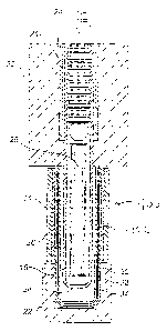
FIGURE 2 is a side elevation view, in section, of a
thermophotovoltaic device constructed in accordance with the
teachings of the present invention.
DETAILED DESCRIPTION OF THE PREFERRED EMESODIMENT
Referring to Figure 1, there is illustrated a PRIOR ART
thermophotovoltaic. The illustration is taken from Canadian
Patent Application 2,399,673 and also appears in
corresponding Patent Cooperation Treaty P.pplication
PCT/CA03/01295.
Referring to FIGS I, There is illustrated a
burner housing 22 in which is positioned a burner 24. Burner
24 has an internal SIC tube 26 and an SIC emitter which
overlies SIC tube 26.
The key teaching of the °673 reference is the use of a
filter 16. As illustrated, filter 16 is made of concentric
quartz glass tubing and has dual walls 30 and 32 with a low
conductivity space 34 positioned between walls 30 and 32.
Low conductivity can be created in space 34 by various means,
preferably, by placing the space under vacuum. Low
conductivity space 34 is adapted to break the convection heat
transfer path from SIC emitter 28 to thermophotovoltaic cells
14. In order to further increase the efficiency of the
device, a dielectric filter 36 is provided. Dielectric
filter 36 is adapted to filter mid-wavelength energy and
overlies filter 16 between SIC emitter 28 and
thermophotovoltaic cells 14.
The preferred embodiment, a thermophotovoltaic device

CA 02444831 2003-10-10
4
with a selective emitter generally ident~_fied by reference
numeral 100, will hereinafter now be described with reference
to gIG~ 2.
For the purpose of illustrating the concept a structure
which is virtually identical to that illustrated in Fire 1
is shown. For the sake of clarity, the same reference
numerals will be used to identify identical components.
There is fundamental difference, which distinguishes the
present invention from the illustrated P~;IOR ART. Atmosphere
is vacated from space 34 to create a vacuum or space is
filled with an inert gas to provide a non.-oxidizing
environment. A selective emitter, indicated by reference
numeral 102 is disposed in space 34 within the non-oxidizing
environment. This significantly alters the mode of operation
and efficiency of thermophotoelectric device 100. There are a
variety of suitable selective emitter materials which can be
used, such as: tungsten, doped magnesia, or rare earth
oxides.
In this patent document, the word '°comprising" is used
in its non-limiting sense to mean that items following the
word are included, but items not specifically mentioned are
not excluded. A reference to an element by the indefinite
article "a°° does not exclude the possibility that more than
one of the element is present, unless the context clearly
requires that there be one and only one of the elements.
It will be apparent to one skilled in the art that
modifications may be made to the illustrated embodiment
witrout departing from the spirit and scope of the invention
as hereinafter defined in the Claims.

Representative Drawing
A single figure which represents the drawing illustrating the invention.
Administrative Status

2024-08-01:As part of the Next Generation Patents (NGP) transition, the Canadian Patents Database (CPD) now contains a more detailed Event History, which replicates the Event Log of our new back-office solution.

Please note that "Inactive:" events refers to events no longer in use in our new back-office solution.

For a clearer understanding of the status of the application/patent presented on this page, the site Disclaimer , as well as the definitions for Patent , Event History , Maintenance Fee  and Payment History  should be consulted.

Event History

Description Date
Inactive: IPC deactivated 2014-05-17
Inactive: First IPC from PCS 2014-02-01
Inactive: IPC from PCS 2014-02-01
Inactive: IPC expired 2014-01-01
Time Limit for Reversal Expired 2007-10-10
Application Not Reinstated by Deadline 2007-10-10
Deemed Abandoned - Failure to Respond to Maintenance Fee Notice 2006-10-10
Inactive: Cover page published 2005-04-10
Application Published (Open to Public Inspection) 2005-04-10
Letter Sent 2004-05-28
Inactive: Single transfer 2004-04-30
Inactive: First IPC assigned 2003-11-27
Inactive: Courtesy letter - Evidence 2003-11-18
Inactive: Filing certificate - No RFE (English) 2003-11-13
Application Received - Regular National 2003-11-12

Abandonment History

Abandonment Date Reason Reinstatement Date
2006-10-10

Maintenance Fee

The last payment was received on 2005-08-16

Note : If the full payment has not been received on or before the date indicated, a further fee may be required which may be one of the following

  • the reinstatement fee;
  • the late payment fee; or
  • additional fee to reverse deemed expiry.

Patent fees are adjusted on the 1st of January every year. The amounts above are the current amounts if received by December 31 of the current year.
Please refer to the CIPO Patent Fees web page to see all current fee amounts.

Fee History

Fee Type Anniversary Year Due Date Paid Date
Application fee - standard 2003-10-10
Registration of a document 2004-04-30
MF (application, 2nd anniv.) - standard 02 2005-10-10 2005-08-16
Owners on Record

Note: Records showing the ownership history in alphabetical order.

Current Owners on Record
ALBERTA RESEARCH COUNCIL INC.
Past Owners on Record
CHRIS ASTLE
GARY KOVACIK
Past Owners that do not appear in the "Owners on Record" listing will appear in other documentation within the application.
Documents

To view selected files, please enter reCAPTCHA code :


To view images, click a link in the Document Description column. To download the documents, select one or more checkboxes in the first column and then click the "Download Selected in PDF format (Zip Archive)" or the "Download Selected as Single PDF" button.

List of published and non-published patent-specific documents on the CPD .

If you have any difficulty accessing content, you can call the Client Service Centre at 1-866-997-1936 or send them an e-mail at CIPO Client Service Centre.


Document
Description 
Date
(yyyy-mm-dd) 
Number of pages   Size of Image (KB) 
Description 2003-10-09 4 182
Claims 2003-10-09 4 89
Abstract 2003-10-09 1 16
Drawings 2003-10-09 2 75
Representative drawing 2004-05-12 1 15
Filing Certificate (English) 2003-11-12 1 159
Courtesy - Certificate of registration (related document(s)) 2004-05-27 1 106
Reminder of maintenance fee due 2005-06-12 1 109
Courtesy - Abandonment Letter (Maintenance Fee) 2006-12-04 1 175
Correspondence 2003-11-12 1 27
Fees 2005-08-15 1 25