Note: Descriptions are shown in the official language in which they were submitted.
CA 02444985 2009-11-13
1
SPIN-ON FILTER ELEMENT AI`TD FILTER HEAD
The present invention relates to liquid filtration systems, and in particular
to spin-
on types of filter elements and filter heads therefor.
Vehicles powered by liquid petroleum fuels, such as diesel fuel or gasoline,
have
fuel systems that typically include fuel filters. The fuel filter operates to
minimize the risk
that contaminates, such as dirt particles or water, will reach other
components of the
system where the contaminates may cause damage.
There are many types of fuel filters known in the prior art. Some provide only
particulate filtration. Others provide filtration and water separation. A
popular
configuration for fuel filters for larger vehicles includes a stationary head
which is
connected in the fuel line of the vehicle fuel system. A replaceable element
attaches to
the head, usually in "spin-on" fashion. The element may be replaced
periodically to
prevent the element from being clogged by contaminates.
One problem with such spin-on elements is that when a filter element is
removed
from the filter head, any fuel remaining in the head can drain out of the head
onto the
operator, the surrounding engine, and/or the ground. This is undesirable from
a clean-up
and environmental standpoint. Air can also enter the head and pass downstream
to the
remainder of the fuel system. This can cause rough operation of the engine
during startup,
as well as damage downstream components.
Another problem is that filter elements with different efficiencies,
applications,
and/or qualities can sometimes fit on the same filter head. It is important to
replace a
spent element with the same or a similar type of element to ensure proper
filtration of the
fuel. It is also important to run the engine with an element installed.
Failing to install an
element can also allow damage to occur to downstream components.
Certain elements have been designed whereby the element can only fit a certain
filter head, and where the filter will not operate without such a filter
element installed.
Patent Specification US-A-5,643,446 to Clausen, for example, shows and
describes a
valve in the filter head which is actuated by an elongated projection on the
filter element.
CA 02444985 2003-10-21
WO 02/089949 PCT/US02/12205
2
The projection extends upwardly from one of the end caps on the element, and
pushes the
valve element upwardly (inwardly) into the filter head when the element is
attached to the
head. The valve generally remains closed if an incorrect element (without such
a
projection) is installed, or if no element is present. The valve also prevents
fuel from
draining out of the filter head when the element is replaced, and prevents air
entering the
filter head.
While the Clausen filter has been useful in many lower-pressure applications,
the
valve in the filter head may open in higher pressure applications. This is
because the fuel
pressure can urge the spring-biased valve inwardly into the head when the
pressure
increases above the cracking force of the spring. Strong springs and robust
valve
elements have therefore been used to keep the valve in a closed position.
However, it can
be more difficult to assemble the filter element on the filter head with such
stronger
springs. The strong springs and robust valve elements also add cost and
complexity to
the filter head--as well as to the filter element, as the projection on the
filter element must
be strengthened. Even with all these precautions, the undesirable opening of
the valve
may still occur in some high pressure situations.
It is therefore believed that there is still a need for a simple, compact,
easy-to-
assemble, spin-on filter element and filter head, where the filter element can
only be used
with a specific filter head, and where the filter will not operate without
such a filter
element installed. It is also believed there is a demand for a filter where
the filter head
prevents fuel draining out of the head, and air entering the head, when the
filter element
is removed.
According to one aspect of the present invention there is provided a filter
element
including a cylindrical housing and a ring of filtration media disposed within
the housing
and circumscribing a central axis. The ring of filtration media includes first
and second
ends, and first and second end caps at the first and second ends of the filter
media ring.
The first end cap includes a first annular threaded portion with threads of a
first pitch, and
CA 02444985 2003-10-21
WO 02/089949 PCT/US02/12205
3
a second annular threaded portion, supported within the housing and co-axially
aligned
with the first annular threaded portion, with threads of a second pitch,
different from the
first pitch.
The present invention provides a novel and unique spin-on type of filter
element
and filter head therefor. Fuel is prevented from draining out of the filter
head and air is
prevented from entering the head, when an element is removed. The filter head
can also
only be used with a specific filter element, and the filter will not operate
without such a
filter element installed.
According to the present invention, the filter head has inlet and outlet
ports. An
annular inlet chamber is provided in the base of the head, and is fluidly
connected to the
inlet port. A threaded nipple is centrally located and projects axially away
from the
base. The nipple includes an internal flow passage fluidly connected to the
outlet port.
A valve assembly including elongated, spring-biased valve member is located in
the flow
passage of the nipple. The valve member is normally biased upwardly into a
closed
position--preventing flow through the passage. A portion of the valve member
projects
outwardly from the nipple. The outwardly-projecting portion includes a series
of threads.
The filter element of the present invention includes a cylindrical housing
enclosing a ring-shaped filter media. The housing preferably includes an open
first end,
and a second end. The second end can be closed, or can be open and include
means to
allow attachment of a collection bowl. End caps are provided at each end of
the filter
media, with an annular portion of each end cap fixed (e.g., adhesively bonded)
to the
respective end of the media. A tap plate encloses the filter element in the
housing, and is
secured to the open end of the housing. The tap plate includes a central
threaded opening,
and a series of peripheral openings spaced radially outward from the central
opening. The
central tap plate opening cooperates with the threaded nipple on the filter
head to allow
the filter element to be screwed on (spun-on) to the filter head. The
peripheral openings
are located for receiving fuel from the inlet chamber of the filter head when
the element is
CA 02444985 2003-10-21
WO 02/089949 PCT/US02/12205
4
attached to the filter head.
The filter element supports a threaded sleeve internally of the element, co-
axially
aligned with the central opening in the tap plate. The threaded sleeve
cooperates with the
threaded valve member of the filter head when the filter element is screwed
onto the head
to cause the valve member to move to an open position. The thread pitch
(angle) on the
valve member/sleeve combination is preferably greater than the thread pitch of
the
nipple/tap plate combination, which causes the valve member to be pulled or
drawn
axially outward from the nipple as the filter element is threaded onto the
filter head,
allowing flow through the nipple. The threaded sleeve can be supported on a
radial end
wall at the internal end of an annular wall extending axially inward into the
media from
the upper end cap, or by other means that rigidly supports the sleeve
centrally in the filter
element. Fluid can pass through the openings in the radial end wall the radial
supports to
the central passage in the nipple and then to the outlet in the filter head
when the filter
element is installed. The threaded sleeve, radial end wall and annular
internal wall are
preferably formed integrally (and more preferably, unitarily) with the annular
portion of
the end cap.
As described above, the screwing of the filter element onto the filter head
causes
the valve member to move to an open position. This enables fuel to flow out of
the filter
element to the outlet of the filter head. Disengagement of the filter element
allows the
valve member to move to a closed position. This prevents air entering the head
and
passing downstream to the remainder of the fuel system when the element is
removed.
This also prevents fuel draining out of the head during an element change.
The threaded sleeve on the filter element is sized and configured so that only
a
sleeve having a certain length, diameter, and thread pitch will properly
engage the threads
on the valve member to draw the valve member to an open position. The sleeve
may have
different configurations with various elements, each of which corresponds to a
particular
filter head. Further, the valve assembly is constructed such that if an
improper element is
CA 02444985 2003-10-21
WO 02/089949 PCT/US02/12205
installed, fuel normally forces the valve member into a closed position, which
prevents
the valve element from opening during high pressure situations. As a result,
only a proper
filter element will operate in conjunction with the filter head, and the
filter head will not
operate without a proper filter element installed.
The invention is diagrammatically illustrated by way of example in the
accompanying drawings in which:
Figure 1 is an elevated perspective view of a filter constructed according to
the
principles of the present invention;
Figure 2 is a cross-sectional side view of the filter taken substantially
along the
plane described by the lines 2-2 of Figure 1;
Figure 3 is a cross-sectional side view of the filter taken substantially
along the
plane described by the lines 3-3 of Figure 1;
Figure 4 is an enlarged, cross-sectional side view similar to Figure 2, but
with the
filter element removed;
Figure 5 is an enlarged, cross-sectional side view similar to Figure 3, but
with the
filter element removed;
Figure 6 is a perspective view of the valve assembly for the filter head;
Figure 7 is a cross-sectional end view of the filter head taken substantially
along
the plane described by the lines 7-7 of Figure 4; and
Figure 8 is an end view of the filter element.
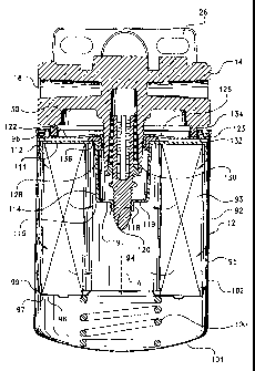
Referring to the drawings and initially to Figures 1-3, there is shown a
filter
assembly 9 including a filter head, indicated generally at 10, and a spin-on
filter element,
indicated generally 12, constructed according to the principles of the present
invention.
The filter element 12 is illustrated as being attached to the filter head, and
is adapted to
be spun onto (and spun off of) the filter head 10, as will be described herein
in more
detail.
CA 02444985 2003-10-21
WO 02/089949 PCT/US02/12205
6
The filter head 10 includes a base 14 with an inlet passage (or port) 16 and
an
outlet passage (or port) 18. The body is shown having multiple inlet and
outlet passages
to enable the head to be easily connected into a fuel system from either side.
Plugs (not
shown) are typically inserted into the unused passages, although certain
applications may
use more than one inlet and/or outlet passage(s). The filter head further
includes a
mounting plate 26 to facilitate mounting the filter head on a vehicle.
Inlet 16 is connected to a fuel line (not shown) which in turn is connected to
a fuel
tank of a vehicle in a conventional manner. Inlet 16 is also in fluid
communication with
an inlet chamber 30 in the filter head. Chamber 30 has an annular
configuration and
opens to the bottom of the filter head. While not shown, appropriate check
valves and/or
a priming pump can be included in the filter head, if so desired. Reference
may be had to
U.S. Patent Nos. 5,362,392 and 5,207,898, for a description of such check
valves.
Referring now to Figures 4 and 5 a cylindrical nipple, indicated generally at
76, is
provided centrally on the filter head base 14, and extends outwardly
(downwardly)
therefrom. Preferably nipple 76 is formed unitary with the base, and includes
a central
cylindrical passage 77 that is fluidly connected at its upper end to the
outlet passage 18.
Threads 78 are provided on the outer surface of the nipple.
A valve assembly, indicated generally at 79, is provided centrally within the
nipple. Valve assembly 79 includes an elongated valve member 80, an annular
seal or
gasket 81, and a compression spring 82. As also shown in Figure 6, valve
member 80
includes a circular body 83 with a series of elongated fingers 84 projecting
axially upward
from one (upper) surface of body 83, and a cylindrical engaging portion 85
extending
axially downward from an opposite (lower) surface of body 83. The engaging
portion 85
includes threads 86 on its outer surface, and a distal end which preferably
terminates in a
conical tip 87. As will be discussed below, the threads 78 on the nipple 76
have a thread
pitch (angle) that is preferably different than the thread pitch (angle) of
the threads 86 on
the valve member 80.
CA 02444985 2007-02-13
7
Spring 82 biases the valve member inwardly (upwardly) into the nipple.
Spring 82 extends between radially outward projecting tabs 88 at the upper end
of
fingers 84 and the upper (inner) surface of annular gasket 81. Gasket 81 is
press-fit or
otherwise secured within the distal end of the nipple, and has a central
opening
slightly larger than the extending fingers of the valve member such that the
valve
member is centered within the nipple, but allowed to move axially therein. The
body
83 of the valve member is wider than the annular seal gasket, and the spring
82 biases
the body of the valve member against the lower surface of the seal/gasket to
provide a
fluid-tight seal therewith. Fingers 84 are preferably equally-spaced around
body 83
such that the spring applies even pressure against the valve member. While
four such
fingers are shown, it should be appreciated that the number of fingers could
vary,
depending upon the particular application.
Seal 81 includes notches or channels as at 88 that receive and guide the
fingers
84 so that the valve member can move easily axially inwardly and outwardly
from the
nipple. The periphery of the body 83 and seal 81 preferably have complementary
tapered or chamfered surfaces to facilitate locating and sealing the valve
member in
the nipple. The spring assembly is thereby initially pre-assembled, and pushed
up into
the nipple. The friction fit of the seal and the notches pi-event the valve
member from
rotating with respect to the nipple, but allow the valve member to move easily
axially
inward and outward from the nipple. The valve member is biased outwardly from
the
nipple by spring 82.
As shown in Figures 2 and 3, filter element 12 includes a cylindrical canister
or housing 92 enclosing a ring of filter media 93. Media ring 93 is preferably
a
conventional type of media appropriate for the particular application. The
media ring
93 circumscribes a central cylindrical chamber 94, and a peripheral annular
chamber
95 is defined between the media ring 93 and canister 92. A first end cap 96 is
provided at one (upper) end of the media, while a second end cap 97 is
provided at the
second (lower) end of the media.
Second end cap 97 entirely closes the lower end of the media to prevent fluid
CA 02444985 2007-02-13
8
flow therethrough, and includes a flat annular body portion 98 fixed (e.g.
adhesively
bonded) to the end of the media, and a short annular skirt 99 surrounding a
portion of
the exterior surface of the media ring.
Second end cap 97 is supported on a compression spring 100, which itself is
supported against the lower end 101 of the canister. Spring 100 prevents the
element
from moving and vibrating within the canister. The canister also includes a
side wall
102, which is preferably formed integral with (and more preferably unitary
with) the
lower end 101, such as by roll seaming or spin-forming, although the lower end
101
could also be a separate component and attached to side wall 102 such as by
welding
or brazing. The lower end of the element could also be entirely open to allow
attachment of a collection bowl, as should be well-known to those skilled in
the art.
Discussion of such a filter element and collection bowl combination can be
found in
U.S. Patent Nos. 5,207,898 and 4,740,299.
The first end cap 96 also includes a flat annular portion 111 fixed (e.g.,
adhesively bonded) to the upper end of the media, and a short annular skirt
112
extending downwardly and surrounding a portion of the media. An imperforate
annular side wall 114 inwardly bounds and extends axially inwards from the
annular
portion 111, preferably in radially spaced-apart relation to the media ring
93. A flat
annular end wall 115 is connected to the axially inner end of the side wall
114, and
projects radially thereacross. A central annular sleeve 118 inwardly bounds
the end
wall 115 and extends axially further inward from the end wall, co-axial with
the
central axis "A" of the element. One or more openings 119 (Figure 2) are
formed in
end wall 115, between side wall 114 and sleeve 118. The number and dimension
of
the openings 119 can be determined depending upon the particular application.
The annular end wall is only one such way to support sleeve 118 centrally in
the housing. The sleeve 118 can be supported using alternative means, and can
be
supported from alternative locations within the element. For example, the
sleeve
could be supported by radially extending spokes extending inwardly from wall
114,
or could be connected directly to second end cap 97, instead of first end cap
96. Other
CA 02444985 2007-02-13
9
appropriate attachment means and locations should be appreciated by those of
ordinary skill in the art, as long as the attachment means rigidly supports
the sleeve
centrally within the element. In any case, sleeve 118 includes internal
threads 120. The thread pitch (angle)
of the threads 120 on sleeve 118 prefei-ably matches the thread pitch (angle)
of the
threads 86 on valve member 80, such that the sleeve can be easily screwed onto
and
off of the valve member. The conical tip 87 on the valve member 80 facilitates
inserting and locating the valve member properly with respect to the sleeve
118.
Preferably the first and second end caps 96, 97 are each formed unitarily, in
one piece, with the threaded sleeve 118, radial end wall 115 and annular side
wall 114
being formed integrally (and more preferably unitarily) with the annular
portion 111
of the first end cap 96. It is possible that the end caps, and particularly
the annular
portion 111 and annular wall 114 of the first end cap 96, can be formed in
separate
pieces and fixed together in an appropriate manner (such as by brazing,
welding, etc.).
A tap plate 122 closes the upper end 123 of the housing. As also shown in
Figure 8, tap plate 122 is preferably a conventional tap plate and includes a
central
circular opening 124 coaxial with the central axis "A" of the housing, and
also co-
axial with sleeve 118. A series of peripheral openings 126 are provided in the
tap
plate, radially outwardly spaced ti-oni the central opening, and located for
receiving
tlow from annular inlet chamber 30 in the filter head. The number of
peripheral
openings 126 can vary, depending upon the flow requirements. The tap plate
includes
a turned-in annular flange 128 bounding the central opening 124 and projecting
a
short distance axially inward. Inwardly-directed threads 130 are formed on the
in-
turned flange 128 of the tap plate. Threads 130 preferably have the same
thread pitch
(angle) as the threads 78 on nipple 76, such that the tap plate can be easily
screwed
onto and off of the nipple. An annular crimp plate 132 secures the tap plate
122 to the
housing. Crimp plate 132 is crimped around the open end 123 of the housing 92,
in a
conventional manner.
Crimp plate 132 includes an outwardly-facing annular groove which receives
CA 02444985 2007-02-13
an annular resilient gasket 134. Gasket 134 seals against the body 14 of the
filter head
when the filter element is assembled with the filter head to prevent fuel
leakage
between the filter head and filter element.
A resilient annular gasket 136 (Figure 2) is also located between the in-
turned
flange 128 of the tap plate and nipple 76. Gasket 136 seals against the
exterior suu=face
of the nipple 76 when the filter element is screwed onto the filter head, and
fluidly
separates the dirty fuel from the clean fuel passing through the filter
element. A thin
membrane (not shown) can be provided across gasket 136 or across sleeve 188 to
prevent contaminants from entering the clean side of the filter element before
the
filter element is attached to the filter head. The point 87 of valve member 80
punctures the membrane when the filter elenlent is installed on the filter
head.
As shown in Figures 4 and 5, the valve niember 80 is noi-mally biased into a
position preventing fuel flow through nipple 76. The circular body 83 of the
valve
member is normally sealed against the annular seal 81. When the element is
screwed
on to the filter head, as shown on Figure 2 and 3, the threads on the valve
member 80
engage the threads on the sleeve 118, and pull the valve member outwardly from
the
nipple. Because the threads on the valve nlember/sleeve combination have a
different
pitch angle than the threads on the nipple/tap plate combination, which pitch
angle is
preferably greater for the valve member/sleeve combination than for the nipple
tap
plate combination, the valve member is pulled axially outward from the nipple
to a
greater extent than the amount that the filter element is screwed onto the
nipple of the
filter head. This results in the valve element being pulled away from the
annular seal,
and thereby opening a flow path between the element and seal.
ln one embodiment, the thi-ead portion of the valve member/sleeve
combination had five (5) threads per inch (TPI), while the threaded portion of
the
nipple/tap plate combination had twelve (12) TPI. This was found to pull the
valve
member .250" (n1m) when the filter element was fully screwed on to the filter
head.
Of course, the number and pitch/angle of the threads can vary depending on the
particular application, and the desired opening of the valve member. In any
case, as
CA 02444985 2007-02-13
il
the valve member is drawn outwardly from the nipple, body 83 of the valve
member
moves away from its seat with the annular seal 81, to thereby allow fuel to
flow from
the central chamber 94 of the filter element, between the body 83 and the seal
81,
between fingers 84, and through the passage 77 to the outlet passage 18.
The threaded sleeve 118 on the filter element is sized and configured so that
only a sleeve having a certain length, diameter, and thread pitch will
properly engage
the threads on the valve member 80 to draw the valve member to an open
position.
The sleeve may have different configurations within various elements, each of
which
corresponds to a particular filter head. Fuel is prevented from flowing
through the
filter head, even during high-pressure conditions, when a filter element is
not
attached, as the tuel pressure normally forces the valve member into a closed
position.
As a result, only a proper filter element will operate in conjunction with the
filter
head, and the filter head will not operate without a filter element attached.
It should be appreciated that while the valve member described above moves
to an open position when it is pulled axially out of the nipple, it is
possible, although
less preferred, that the valve member could be configured to open when it is
pushed
axially into the nipple. The valve member would then be biased outwardly by a
spring
into sealing relation with a portion of the nipple. In this case, the pitch
angle of the
valve member/sleeve combination would be chosen so as to be less than the
pitch
angle of the nipple/tap plate combination, so that the valve member would be
opened
as the filter element was installed on the filter head. Since high fuel
pressure could
open the valve, unless a strong spring were used, this is a less-desirable
(although still
possible) configuration.
It is also noted that the filter element could have a threaded attachment
means
other than the central threaded opening in the tap ring by which to secure the
filter
element to the filter head. For example, the open end of the housing for the
filter
element could include a ring-shaped member around its outer periphery, and the
base
14 of the filter head could have a corresponding ring-shaped member, which
would
allow the tilter element to be screwed on to the filtei- head. Such coopei-
ating ring-
CA 02444985 2007-02-13
12
shaped members are shown, for example, in Jensen, U.S. Patent No. 6,328,883
entitled "Fuel Filter Assembly With Priming Pump". In this case, the thread
pitch of
the valve member/sleeve would be different (preferably greater than) than the
thread
pitch of the ring-shaped members of the filter element and filter head so that
the valve
member is again opened during attachment of the element to the head. It is
also
possible that the cylindrical wall 114 could be secured directly to the tap
plate (or
whatever component encloses the open end of the housing), rather than to the
annular
body portion of the upper end cap. An appropriate seal would then be provided
between the annular body portion and the cylindrical wall to prevent fluid by-
pass of
the element.
The fuel flows through the filter element and through the end cap structure of
the filter element and the nipple structure of the filter head as described
above,
without substantial restriction. When the element is replaced, the valve
element in the
filter head closes, which prevents fuel dripping or draining out of the head,
and
prevents air entering the filter head. The screw-type valve member also
prevents the
filter head from being used without a filter element installed, as the valve
member
remains closed, even during high-pressure operation. As a result, only a
proper filter
element will operate in conjunction with the filter head, and the filter head
will not
operate without a filter element attached.