Note: Descriptions are shown in the official language in which they were submitted.
CA 02445138 2003-10-10
S EC I I° I ~!'l~l
Humidifies bottle latch carry handle
Background of Invention
[0001 ] Field of the Invention.
[0002) The present invention relates generally to humidifiers, and more
specifically, to a
latch for fastening a removable humidification housing to a mounted water
bottle
thereby maintaining the rigidity of the humidifier during lifting and
carrying.
[0003] Description ofReiated Art,
[0004] Humidifiers are well known and commonly used in households and
businesses to
add moisture to indoor air providing a more comfortable Living environment. A
comfortable level of humidity is generally 30-50% in the winter and 40-50~ in
the
summer. If the humidity level is lower, atopic dermatitis, excessive static
eiectricity,
drying out of furniture and other various concerns may occur. A humidifier's
many
advantages include: alleviating a cold sufferer's sore throat, reducing any
difficulty in
breathing, and generally improving the health and comfort of the user's home.
(0005] Several varieties of humidifiers exist, differing in bath
humidification methods,
[0006]
size and refilling. The method of humidification varies from evaporative,
ultrasonic,
cool mist impeller, steam vaporizers and warm mist humidifiers. The present
invention is direeted to an evaporative humidifier, which is often called a
wicking
humidifier because is employs a Large wick or filter. The wick or filter draws
water
upward from a water reservoir base through capillary action. A fan blows air
across or
through the filter thereby diffusing moisture throughout the room.
The varying sizes include table top, console and central humidifiers. ~lhile
tabletop designs typically humidify one roam, console and central humidifiers
may
humidify multiple rooms or an entire house. Table top and console humidifiers
require
1
CA 02445138 2003-10-10
manual filling of the water while central humidifiers connect directly to the
water
pipeline of the house. The humidifier of the present invention is generally
directed to
a console humidifier, but has application to a tabletop design as well.
j0007] Refilling a humidifier generally varies between a bottle fill design
and a bucket fill
design. i3ottle fill designs have removable bottles for supplying the
humidification
humidifier with water. This enables the user to transport the bottle
individually to the
nearest sink for refilling. The reasonable size of the bottle and its
removability from
the humidifier make it easy to transport and causes little mess. In a bucket
fill design,
however, a standard bucket or pitcher must be used to carry water from the
sink to
refill the humidifier as needed. Although the user may transport varying
amounts of
water depending on the strength of the user, the bucket fill design may
require
several trips and cause excessive spillage. The present invention is directed
to a bottle
fill humidifier.
[00g8] One common goal of both console and tabletop models is to provide a
simple
means to lift and carry the humidifDer. Such a design is ~fc~und in U.S.
Patent 5,480,588
issued in the name of Tomasiak (Tomasiak) and incorporated herein by reference
in its
entirety. Among other things, the disclosure of the Tomasiak patent provides
for a
water reservoir base with a centrally located humidification housing and two
spaced
water bottles mounted to opposing end portions of the base. An integrally
molded
handle is provided at the upper ends of each bottle for lifting and carrying
of the
humidifier. Each handle has an elongated opening formed on the underside of
the
handle so that a user's fingers may comfortably grasp the handle and transport
the
humidifier.
[0009]
Humidifier filters generally need replacing once a season because they gather
impurities leading to discoloration of the filter. Once the filter becomes
distinctly
discolored, a replacement is necessary. In some prior art humidifiers, a
screwdriver or
other implement must be used to pry open a grill covering the filter. After
the filter is
replaced, the grill must be realigned and remounted to the humidifier. Placing
the
humidification housing on the base where a user only lifts it straight up to
remove
provides a simple means for accessing and replacing the filter. As fewer parts
are
involved and no implements must be used, reliability arid efficiency is
increased. ,
2
CA 02445138 2003-10-10
However, which such a design, when transporting the humidifier the housing
becomes
unstable and may separate from the base.
[0010] Thus, there is a need far a simple means of accessing and replacing the
filter
while still maintaining the rigidity of the humidifier. The present invention
addresses
associated shortcomings in the prior art.
Summary of Invention
[0071] In accordance with aspects of the present invention, a humidifier
includes a water
reservoir base, a humidification housing removably positioned on the base, at
least
one water bottle for dispensing water into the base, and a latch for fastening
the
housing to the bottle thereby securing the housing to the base by means of the
mounted bottle. The latch may be connected to the housing or the bottles. in
same
embodiments, the battle includes a handle at an upper end of the bottle. The
latch
may be pivotally attached to the housing and pivot to fasten the housing to
the bottle.
Further, the latch may adjoin to the underside of the bottle handle in the
fastened
position. fn other embodiments, the latch is mounted on the bottle and fastens
to a
raised edge defined by the housing. The bottle may bs removably mounted to the
base, for example, via prongs extending from the bottle that is arranged to be
received by corresponding tangs defined by the base.
Brief ~escription of ~rawings
[0012] Other objects and advantages of the invention will become apparent upon
reading
the following detailed description and upon reference to the drawings in
which:
[0013] FIG. 1 illustrates a perspective view of a bottle fill humidifier in
accordance with an
exemplary embodiment of the present invention.
j0014] FIG. z is a partial view of the bottom portion of a humidiiaer bottle
in accordance
with aspects of the present inventian.
[0015] FIG. 3 is a sectional view of a portion of a humidifier in accordance
with the
present invention, illustrating an exemplary arrangement for mounting the
battle to
the humidifier base.
3
~ 02445138 2003-10-10
[0016] F1G. ~ illustrates a partial perspective view of a bottle latch in
accordance with the
exemplary embodiment of the present invention.
[0017] FIG. 5 is a cross-sectional view of the bottle latch shown in Fig. 4.
(0018] FIG. 6 is a cross-sectional view of a bottle latch in accordance with
an alternative
embodiment of the present invention.
[0019] FIG. 7 illustrates a partial perspective view of a humidifier
incorporating the bottle
latch as shown in FIG. 6.
(0020] FIG. 8 is a cross-sectional view of a bottle latch in accordance with
another
alternative embodiment of the present invention.
[0021 ] FIG. 9 illustrates a partial perspective view of a humidifier
incorporating the bottle
latch as shown in FIG. 8.
[0022] FIG. 10 is a cross-sectional view of a fastening means in accordance
with an
alternative embodiment of the present invention.
(0023] . F1G. 1 1 illustrates a partial perspective view of a humidifier
incorporating the
fastening means as shown in FIG. 10 in accordance with an alternative
embodiment of
the present invention.
[0024] While the invention is susceptible to various modifications and
alternative forms,
specific embodiments thereof have been shown by way of example in the drawings
and are herein described in detail. It should be understc~od9 however, that
the
description herein of specific embodiments is not intended to limit the
invention to
the particular forms disclosed, but on the contrary, the Intention is to cover
al(
modifications, equivalents, and alternatives falling within the spirit and
scope of the
invention as defined by the appended claims.
Detailed Description
[0025] Illustrative embodiments of the invention are described below. In the
interest of
clarity, not all features of an actual implementation are described in this
specification.
It will of course be appreciated that in the development of any such actual
embodiment, numerous implementation-specific decisions must be made to achieve
4
CA 02445138 2003-10-10
the developers' specific goals, such as compliance with system-related and
business-
related constraints, which will vary from one implementation to another.
Moreover, it
will be appreciated that such a development effort might be complex and time-
consuming, but would nevertheless be a routine undertaking for those of
ordinary
skill in the art having the benefit of this disclosure.
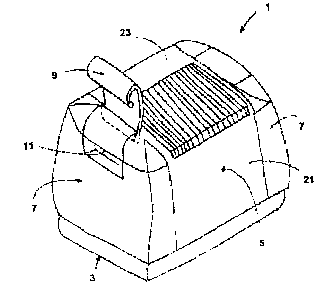
[0926] Turning to the figures, and in particular Fig. 1, an exemplary
humidifier in
accordance with aspects of the present invention is illustrated. A removable
humidification housing 5 sits on top of a water reservoir base 3. A water
bottle 7 is
mounted to the base 3. In the embodiment illustrated in Fig. l, two bottles 7
are
positioned adjacent to and on opposing sides of the housing 5.
[0027) The water bottles 7 may be mounted to the base 3 in the manner
disclosed in the
incorporated Tomasiak patent, U.S. Patent 5,480,588. Fig. 2 illustrates the
lower part
39 of the humidifier bottle 7. The bottle 7 includes a water dispensing cap 41
having
a dispensing valve 42. The bottles 7 are received by the base 3 for providing
water
thereto via the valve 42, while at the same time the bottles 7 provide lifting
and
carrying elements for the humidifier 1. To this end, spaced depending prongs
37
extend from the bottom of the bottle 7 and corresponding tangs 53 are received
within an openings 39 of the depending prongs 37 as shown in Fig. 3.
[9028] The housing 5 comprises an upwardly extending sidewall 21 that supports
a top
portion 23 as shown, for example, in Fig. 1. The user m,ay remove the housing
5 to
easily access the filter (not shown) by first unfastening a~ latch 9 thereby
ailowing
aceess to the bottles 7. The bottles 7 may be removed by tilting them away
from the
housing 5 to disengage the prongs 37 from the tang 53 and then lifting the
bottle 7
up. Once the bottles 7 have been removed, the user can lift the housing S
straight up
to clear the filter (not shown.
[0029] In the exemplary embadiment shown in Fig. 1, the latch 9 is mounted to
the top
portion 23 of the housing 5 as is further shown in Figs. 4-5. In the fastened
position,
the latch 9 may pivot around a fulcrum 17 to fasten to the bottle 7. The
bottle 7 may
further include a handle 11 situated at an upper end of 'the bottle 7. This
handle 1 1
forms a depression 1 S on the under side of the handle -I 1 thus allowing the
user to
comfortably fit his jher fingers inside for lifting and carrying the bottle 7
when
CA 02445138 2003-10-10
separated from the humidifier 1, such.as for refilling with water, or for
carrying the
humidifier 1 when the bottles 7 are mounted in the base 3. In the fastened
position
the latch 9 pivots towards the bottle 7 and resiliently flexes around the
handle 11. The
latch 9 may further adjoin with at least a portion of the underside of the
handle 1 T
thereby allowing adequate space for the user's fingers to fit within the
depression 15.
Additionally, in the exemplary embodiment the latch 9 naay pivot upwards and
away
from the bottle 7 in the unfastened position. This allows the user to freely
access the
bottle 7 for removal.
[0030] Figs. 6 and 7 illustrate an alternative embodiment of the present
invention,
wherein the latch 9 has a circular fastening end 29. The latch 9 is mounted to
the
housing 5 and pivots around the fulcrum T 7 to fasten wiithin a notch 27
formed in the
top portion 31 of the bottle 3. As shown in Fig. 7, the depression T 5 of the
handle 11
remains freely accessible by a user. '
[0031] Figs. 8-11 illustrate alternative embodiments of the humidifier bottle
latch
wherein the latch 9 is mounted to the bottle 7. The latch 9 is pivotally
fastened to the
housing 5 and has a latching end 26 and an activation end 28. The latching end
26 of
the latch 9 may mate with a raised edge 25 formed in the housing 5. The latch
9 may
be biased such that the latching end 26 is normally positioned downwardly as
viewed
in Figs. 8-1 l, i~ a latched position. In the embodiments illustrated, the
activation end
28 is pushed down to lift the latching end 26 such that it clears the edge 25.
Again, as
shown in Fig. 7, the depression T 5 remains freely accessible by a user while
the
removable housing 5 remains secured to the base 3 by rneans of the mounted
bottle
7. In the version shown in Figs. 10-11, the latch 9 extents approximately the
width of
the bottle 7.
joo32]
The particular embodiments disclosed above are illustrative only, as the
invention
may be modified and practiced in different but equivalent manners apparent to
those
skilled in the art having the benefit of the teachings herein. Furthermore, no
limitations are intended to the details of construction or design herein
shown, other
than as described in the clairrls bet~w. It is therefore evident that the
particular
embodiments disclosed above may be altered or modified and all such variations
are
considered within the scope and spirit of the invention. Accordingly, the
protection
6
CA 02445138 2003-10-10
sought herein is as set forth in the claims below.
7