Note: Descriptions are shown in the official language in which they were submitted.
CA 02445237 2003-10-16
13DV 14281
METHOD OFREPAIRING A STATIONARY SHROUD OF A GAS TURBINE
ENGINE USING PLASMA TRANSFERRED ARC WELDING
This invention relates to aircraft gas turbine engines and, more particularly,
to the
repair of a stationary shroud that has previously been in service.
BACKGROUND OF THE INVENTION
In an aircraft gas turbine (jet) engine, air is drawn into the front of the
engine,
compressed by a shaft-mounted compressor, and mixed with fuel. The mixture is
burned, and the hot combustion gases are passed through a gas turbine mounted
on
the same shaft. The flow of combustion gas turns the gas turbine by
impingement
against an airfoil section of the turbine blades and vanes, which turns the
shaft and
provides power to the compressor. The hot exhaust gases flow from the back of
the
engine, driving it and the aircraft forward.
In the gas turbine, an annular, circumferentially extending stationary shroud
surrounds the tips of the rotor blades. The stationary shroud confines the
combustion
gases to the gas flow path so that the combustion gas is utilized with maximum
efficiency to turn the gas turbine. The clearance between the turbine blade
tips and the
stationary shroud is minimized to prevent the leakage of combustion gases
around the
tips of the turbine blades. The stationary shroud provides a rubbing surface
for the
tips of the turbine blades. The design intent is for the turbine blade tips to
rub into the
stationary shroud, with the contact acting in the manner of a seal. The
clearance
between the blade tips and the stationary shroud, and thence the amount of
combustion gas that can bypass the turbine blades, is minimized, thereby
ensuring
maximum efficiency of the engine. The stationary shroud must be manufactured
to
and maintained at highly exacting tolerances in order to achieve this
efficiency during
extended service.
1
CA 02445237 2003-10-16
13DV14281
The gas path surface of the stationary shroud is exposed to abrasion by the
rotating
turbine blade tips and also to erosion, oxidation, and corrosion by the hot
combustion
gases. The base metal of the stationary shroud is typically not highly
resistant to the
environmental attack and abrasion, and therefore an environmentally resistant
rub
coating is applied on the gas path surface of the stationary shroud. Over a
period of
time as the engine operates, the surface of the environmentally resistant rub
coating
is worn away, and some of the base metal of the stationary shroud may also be
damaged and/or removed. The result is that the dimensions of the stationary
shroud
are reduced below the required tolerances for efficient operation of the gas
turbine
engine. Alternatively stated, the annular radius of the inwardly facing
surface of the
stationary shroud gradually increases, so that an increasing amount of
combustion gas
leaks around the tips of the turbine blades and the operating efficiency is
reduced. At
some point, the stationary shroud is no longer operating acceptably and the
operation
of the gas turbine degrades below acceptable levels.
Because of the high cost of the stationary shroud materials, rather than
dispose of the
stationary shrouds, it is desirable to repair the stationary shrouds by
restoring the
stationary shrouds to their original dimensions in accordance with preselected
tolerances as determined by the engine's size as well as to restore the
corrosion
resistant properties to the flow-path surfaces. In the past, this restoration
has been
accomplished by low pressure plasma spray (LPPS), thermally densified coatings
(TDC), the high-velocity oxyfuel (HVOF) process, or activated diffusion
healing
(ADH). The first three approaches restore the stationary-shroud dimensions
using the
rub-resistant coating material but do not restore the structural strength of
the
underlying shroud base metal. The fourth approach repairs holes and cracks in
the
shroud base metal, prior to re-application of the rub-resistant coating
material.
In the work leading to the present invention, the inventors have observed that
these
approaches achieve the desired restoration of the dimensions of the stationary
shroud,
but do not restore its mechanical performance. The stationary shroud no longer
has
2
CA 02445237 2003-10-16
13DV14281
its necessary mechanical properties, so that there is a risk of mechanical
failure of the
stationary shroud. There is needed an approach by which the mechanical
properties
as well as the dimensions of the coated stationary shroud are restored. The
present
invention fulfills this need, and further provides related advantages.
BRIEF SUMMARY OF THE INVENTION
The present invention provides a technique for restoring the mechanical
properties as
well as the dimensions, environmental resistance, and rub resistance of the
flow-path
surface of a stationary shroud of a gas turbine engine, and a stationary
shroud repaired
by this approach. The present method is typically utilized after the gas
turbine engine
has been in service and the stationary shroud has been subjected to extended
operation
in combustion gas, high temperatures, and rubbing from the movement of the
turbine
blades. The present approach may be utilized with conventional procedures
known
for use in other applications.
A method for repairing a stationary shroud of a gas turbine engine comprises
the steps
of furnishing the stationary shroud that has previously been in service, the
stationary
shroud being made of a base metal, removing any damaged material from a flow-
path
region of the stationary shroud to leave an initially exposed base-metal flow-
path
surface, and applying a base-metal restoration overlying the initially exposed
flow-
path surface. The step of applying includes the steps of furnishing a source
of a
structural material that is compatible with the base metal, and depositing the
source
overlying the initially exposed base-metal flow-path surface of the stationary
shroud
by plasma transferred arc (PTA) welding to form a repaired base-metal flow-
path
surface. The base-metal restoration is typically in-process machined to its
desired
dimensions, shape, and surface finish.
The source of the structural material may have substantially the same
composition as
the base metal, or a different composition. The source of the structural
material may
be a powder. A plasma transferred arc welder beam may be directed toward the
3
CA 02445237 2003-10-16
13DV 14281
initially exposed flow-path surface, and simultaneously the powder of the
structural
material may be injected into the plasma transferred arc welder beam so that
the
powder is fused and deposited. The source of the structural material may
instead be
a wire that is fed into the plasma transferred arc welder beam and fused onto
the
surface that is being restored.
The stationary shroud may be any stationary shroud, but it is preferably a
high
pressure turbine stationary shroud. The stationary shroud may be made of any
operable material, but it is preferably made of a nickel-base alloy or a
cobalt-base
alloy.
Preferably, an environmentally resistant rub coating is thereafter applied
overlying
the base-metal restoration. The an environmentally resistant rub coating
defines a
rub-coating surface, and the rub-coating surface is typically shaped, as by
machining,
to the required shape and dimensions. While this rub-coating material may be
any
corrosion resistant, oxidation resistant and rub tolerant powder, MCrAIY
compositions have been found to be most suitable.
The present invention is an advancement of current technology for repairing
and
restoring shrouds for engine service. Unlike stationary shrouds repaired by
the TDC
process, stationary shrouds repaired in accordance with the present invention
are not
temperature-limited because of additions of melting point depressants such as
boron
or silicon. The present invention is also an advance over the (LPPS) process,
since
no partial vacuum is required, making the process faster, cheaper, more
effective and
easier to perform. Other advantages include less process variation and no
preheat to
overshoot or undershoot. Very importantly, there is much less part distortion,
so that
the ability to restore the shroud segments to the original. drawing tolerances
can be
done more easily and with less machining. A less expensive powder material is
used
in the present approach, as compared with HVOF. The present approach provides
achieves results superior to ADH, because the stationary shroud is restored to
its
original dimensions using a structural material, rather than the rub-resistant
coating.
4
CA 02445237 2003-10-16
13DV 14281
The rub-resistant coating is preferably applied over the dimensionally
restored base
metal of the stationary shroud.
Other features and advantages of the present invention will be apparent from
the
following more detailed description of the preferred embodiment, taken in
conjunction with the accompanying drawings which illustrate, by way of
example, the
principles of the invention.
BRIEF DESCRIPTION OF THE DRAWINGS
Figure 1 is a cross-sectional view of a stationary shroud assembly, showing a
shroud
segment and the shroud flow-path surface adjacent to the tip of a turbine
blade, the
shroud support, the shroud hanger support and the support case;
Figure 2 is a perspective view of a stationary shroud segment;
Figure 3 is a partial perspective view of a stationary shroud assembly,
comprised of
a series of shroud segments assembled to form a portion of a cylinder around
turbine
blades;
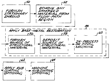
Figure 4 is a block flow diagram of an approach for practicing the present
approach;
Figure 5 is a schematic sectional view of the stationary shroud showing the
layers of
the restoration, taken generally on line 5-5 of Figure 2;
Figure 6 is a schematic view of the use of injected powder in plasma
transferred arc
welding; and
Figure 7 is a schematic view of the use of a wire feed in plasma transferred
arc
welding.
DETAILED DESCRIPTION OF THE INVENTION
Figure 1 is a cross-sectional view generally depicting a stationary shroud
assembly 20 in
relation to a turbine blade 22. The stationary shroud assembly 20 includes a
stationary
CA 02445237 2006-09-28
13DV14281
shroud 24 having a flow-path surface 26 in a facing relation to a turbine
blade tip 28
of the turbine blade 22. (The term "stationary shroud" as used herein refers
to
structure which does not rotate as the turbine blade 22 turns with its
supporting
turbine disk (not shown) and turbine shaft (not shown). The stationary shroud
24 is to
be distinguished from the rotating shroud that is found at the tip of some
other types
of blades and is a part of the blade, and which does rotate as the blade
turns.) A small
gap 30 separates the flow-path surface 26 from the turbine blade tip 28. The
smaller is
the gap 30, the less hot combustion gas 44 that can leak through the gap 30
and not
participate in driving the turbine blade 22. Also depicted are a stationary
shroud
support 32 from which the stationary shroud 22 is supported, a stationary
shroud
hanger support 34 from which the stationary shroud support 32 is supported,
and a
support case 36 from which the stationary shroud hanger support 34 is
supported.
For reasons of manufacturing, assembly, and thermal expansion compatibility,
the
stationary shroud 24 is typically formed of a circumferentially extending
series of
individual stationary shroud segments 38. Figure 2 illustrates one of the
stationary
shroud segments 38, and Figure 3 depicts the manner in which the individual
stationary shroud segments 38 are assembled together in a circumferentially
abutting
fashion to form the annular, generally cylindrical stationary shroud 24. The
structure
of the stationary shrouds is described more fully in US Patent 6,233,822.
When the gas turbine engine is operated, the turbine blades 22 rotate. As they
rotate
and are heated to elevated temperature, the turbine blades 22 elongate so that
the gap
30 is reduced to zero and the turbine blade tips 28 contact and cut into the
flow-path
surface 26 and wear away the material of the stationary shroud 24 at the flow-
path
surface 26. Over time, the gap 30 becomes larger as material is abraded from
both the
turbine blade tips 28 and the stationary shroud 24, and also lost from the
turbine blade
tips 28 and the stationary shroud 24 by erosion, oxidation, and corrosion in
the hot
combustion gases. As the gap 30 becomes larger, the efficiency of the gas
turbine
decreases. At some point, the gas turbine engine is removed from service and
repaired.
6
CA 02445237 2003-10-16
13DV14281
Figure 4 depicts a preferred approach for repairing the stationary shroud 24.
The
stationary shroud 24 that has previously been in service is furnished, step
50. In the
case of most interest, the stationary shroud 24 is a high pressure turbine
stationary
shroud. The stationary shroud is made of a base metal 42, see Figure 5. The
base
metal 42 of the stationary shroud 24 is preferably either a nickel-base alloy
or a
cobalt-base alloy. Examples of such base-metal alloys include L605, having a
nominal composition by weight of about 20 percent chromium, about 10 percent
nickel, about 15 percent tungsten, about 3 percent iron, about 1 percent
silicon, about
1.5 percent manganese, about 0.1 percent carbon, and the balance cobalt and
incidental impurities; ReneTM N5, having a nominal composition by weight of
7.5
percent cobalt, 7 percent chromium, 6.2 percent aluminum, 6.5 percent
tantalum, 5
percent tungsten, 3 percent rhenium, 1.5 percent molybdenum, 0.15 percent
hafnium,
0.05 percent carbon, 0.004 percent boron and the balance nickel and incidental
impurities; IN-738 having a nominal composition by weight of 8.5 percent
cobalt, 16
percent chromium, 3.4 percent aluminum, 3.8 percent titanium, 1.75 percent
tantalum,
2.6 percent tungsten, 1.75 percent tantalum, 0.012 percent boron 0Ø12
percent
zirconium, 0.05 percent niobium and the balance nickel and incidental
impurities;
ReneR 77, having a nominal composition in weight percent of about 14.6
chromium,
about 15.0 percent cobalt, about 4.2 percent molybdenum, about 4.3 percent
aluminum, about 3.3 percent titanium, about 0.07 percent carbon, about 0.016
percent
boron, about 0.04 percent zirconium, balance nickel and minor elements; and
MarM509, having a nominal composition by weight of about 10 percent nickel,
about
0.6 percent carbon, about 0.1 percent manganese, about 0.4 percent silicon,
about 22.5
percent chromium, about 1.5 percent iron, about 0.01 percent boron, about 0.5
percent
zirconium, about 7 percent tungsten, about 3.5 percent tantalum, and the
balance
cobalt and incidental impurities. This listing is exemplary and not limiting,
and the
present approach may be used with any operable material.
Any damaged material is removed from a flow-path region 40 of the stationary
shroud
24, step 52, to leave an initially exposed base-metal flow-path surface 70,
see Figure
7
CA 02445237 2003-10-16
13DV 14281
5. The flow-path region 40 generally corresponds with the location of the flow-
path
surface 26 of Figure 1, but is not exactly coincident because of the presence
of
damaged material and the loss of base metal 42 during service. The damaged
material
may include remnants of the prior rub coating, damaged base metal, and
oxidation,
corrosion, and erosion products, as well as soot. The damaged material may be
removed by any operable approach. In one approach, the flow-path region 40 is
first
degreased by any operable approach. The flow-path region 40 is then ground or
grit-blasted to remove any tightly adhering oxides. Next the flow-path region
40 is
acid stripped to remove the aluminides, followed by a fluoride-ion cleaning
(FIC).
A typical result of this removal of damaged material, and the prior removal of
base
metal 42 by oxidation and abrasion during service, is that the thickness to of
the base
metal 42 in a backside-pocket (thinnest) portion 74 of the flow-path region 40
of the
stationary shroud 24 is too thin, and below the thickness required by the
specifications. This sub-specification thickness is undesirable, because if a
rub
coating were applied directly to the exposed surface at this point, the
stationary
shroud 24 would have insufficient mechanical properties and insufficient
resistance
to bowing (chording) when returned to service.
A base-metal restoration 72 is applied overlying and in contact with the
initially
exposed flow-path surface 70 in the flow-path region 40, step 54. The base-
metal
restoration 72 has a thickness tA that, when added to to, increases the
thickness of the
backside-pocket portion 74 of the flow-path region 40 to a restored thickness
tR,
which is within the tolerance range of the thickness specification for the
backside-
pocket 74.
The step of applying 54 includes the steps of furn.ishing a source of a
structural
material that is compatible with the base metal 42, step 56, and depositing
the
structural material overlying the initially exposed base-metal flow-path
surface 70 of
the stationary shroud 24 by plasma transferred arc (PTA) welding to form a
repaired
8
CA 02445237 2003-10-16
13DV 14281
flow-path surface 76, step 58. Plasma transferred arc welding is a known
process for
other applications.
The structural material used in the restoration step 54 to apply the base-
metal
restoration 72 may have substantially the same composition as the base metal
42. The
use of substantially the same composition for the restoration as the base-
metal
composition is preferred, so that the base metal 42 of the stationary shroud
24 and the
base-metal restoration 72 are fully compatible both chemically, in respect to
properties such as the formation of new phases through interdiffusion, and
physically,
in respect to properties such as the bonding of the base metal 42 and the base-
metal
restoration 72, avoiding mismatch of the coefficients of thermal expansion,
and
melting points. The structural material used in the restoration step 54 to
apply the
base-metal restoration 72 may instead have a different composition than the
base
metal 42 to achieve particular properties that may not be achievable when the
base-
metal restoration 72 is the same composition as the base metal 42.
Two approaches are of particular interest for depositing the structural
material by
plasma transferred arc welding, step 58, as depicted in Figures 6-7. In the
approach
shown in Figure 6, a plasma transferred arc welder beam 82 is directed from
the
plasma transferred arc welder 80 toward the initially exposed flow-path
surface 70.
Simultaneously, a powder flow 84 of the restoration powder is injected from a
powder injector 86 into the plasma transferred arc welder beam 82 and upon the
initially exposed flow-path surface 70 so that the powder is fused and
deposited onto
the initially exposed flow-path surface 70. The power level of the plasma
transferred
arc welder 80 is selected so that the injected powder is melted and the
topmost portion
of the base meta142 is melted, but that the underlying portion of the base
metal 42 is
not melted. The plasma transferred arc welder 80 and the powder injector 86
move
together laterally across the initially exposed flow-path surface 70, so that
the injected
powder is progressively melted when exposed to the plasma transferred arc
welder
beam 82, and then progressively allowed to solidify as the plasma transferred
arc
9
CA 02445237 2003-10-16
13DV14281
welder 80 moves onwardly and no longer heats a particular area.
In the approach of Figure 7, the plasma transferred arc welder beam 82 is
directed
from the plasma transferred arc welder 80 toward the initially exposed flow-
path
surface 70. Simultaneously, a wire 88 of the structural material is fed into
the heated
zone with a wire feed, schematically indicated by a wire feed arrow 90, so
that the
metal of the wire 88 is fused and deposited onto the initially exposed flow-
path
surface 70. The wire 88 may be supplied in discrete lengths or as a continuous
coil.
The power level of the plasma transferred arc welder 80 is selected so that
the wire
88 is melted and the topmost portion of the base metal 42 is melted, but that
the
underlying portion of the base metal 42 is not melted. The plasma transferred
arc
welder 80 and the wire feed 90 move together laterally across the initially
exposed
flow-path surface 70, so that the injected powder is progressively melted when
exposed to the plasma transferred arc welder beam 82, and then progressively
allowed
to solidify as the plasma transferred arc welder 80 moves onwardly and no
longer
heats a particular area.
The two approaches of Figures 6 and 7 may be combined as well, with some of
the
source of the structural material being introduced as a powder as in Figure 6,
and
some of the source of the structural material being introduced as a wire, as
in Figure
7.
The present approach offers distinct advantages over other techniques. The
flow-path
region 40 which the base-metal restoration 72 is applied is typically rather
thin. To
avoid distorting the thin base metal 42, it is desirable that the heat input
during the
restoration 54 be no greater than necessary. The plasma transferred arc welder
80 has
a much lower heat input than other techniques such as a TIG welder, so that it
melts
the restoration material but does not introduce more heat than necessary.
However,
because the restoration material and the uppermost portion of the initially
exposed
flow-path surface 70 are melted during the heating, there is a strong
metallurgical
bond between the restoration 72 and the underlying base metal 42, unlike some
other
CA 02445237 2003-10-16
13DV14281
techniques such as some thermal spray processes. The present approach also
produces
a relatively large grain size in the restoration 72, when compared to LPPS and
HVOF
processes, which is desirable for creep and rupture properties.
In any case, the result is the solidified base-metal restoration 72, with its
repaired
flow-path surface 76, deposited overlying and upon the initially exposed flow-
path
surface 70. As noted above, the amount of structural material restoration 72
applied
in step 54 is such that, after the deposition step 58, the thickness tR (= to
+ tA) is
desirably within a pre-defined specification range required for the stationary
shroud
24 to be returned to service. However, it is difficult to achieve that result
precisely
and with a highly uniform surface, and the usual approach is to deposit the
structural
material to be slightly thicker than desired.
The deposited base-metal restoration is then in-process machined, numeral 60,
so that
the total restored thickness tR of the base metal is the desired value and the
shape of
the repaired base-metal flow-path surface 76 is correct. The powder deposition
process 58 is not sufficiently precise to achieve exactly the correct
thickness and
shape, and the in-process machining step 60 is used.
Optionally but strongly preferred, an environmentally resistant rub coating 78
is
applied overlying and contacting the base-metal restoration 72, step 62. The
rub
coating 78 is preferably a material, typically in the form of a powder and
having
enhanced environmental resistance which is rub compliant. Examples of such rub
coating materials include an MCrAIY(X) where M is an element selected from the
group consisting of cobalt and nickel and combinations thereof and (X) is an
element
selected from the group of solid solution strengtheners and gamma prime
formers
consisting of titanium, tantalum, rhenium, molybdenum, and tungsten, and grain
boundary strengtheners consisting of boron, carbon, hafnium, and zirconium,
and
combinations thereof; and BC-52 alloy, having a nominal composition, in weight
percent, of about 18 percent chromium, about 6.5 percent aluminum, about 10
percent
cobalt, about 6 percent tantalum, about 2 percent rhenium, about 0.5 percent
hafnium,
11
CA 02445237 2003-10-16
13DV14281
about 0.3 percent yttrium, about 1 percent silicon, about 0.015 percent
zirconium,
about 0.015 percent boron, about 0.06 percent carbon, the balance nickel and
incidental impurities. The rub coating is applied by any operable approach,
but
preferably by the HVOF (high-velocity oxyfuel) process. The rub coating 78 is
preferably in the range of about 0.005-0.150 inches in thickness, most
preferably in
the range of from 0.005-0.050 inches in thickness. The HVOF process, which
utilizes
a high velocity gas as a protective shield to prevent oxide formation, is a
relatively
low temperature thermal spray that allow for applicatior.L of a high density
oxide-free
coating in a wide variety of thicknesses, is known in the art. The HVOF
process
typically uses any one of a variety of fuel gases, such as oxygen,
oxypropylene,
oxygen/hydrogen mixtures or kerosene. Gas flow of the fuel can be varied from
2000-5000 ft/sec. Of course, the temperature of the spray will depend on the
combustion temperature of the fuel gas used, but will typically be in the
range of
3000-5000° F. Preferably, a slight excess thickness of the rub coating
78 is
applied, and then the excess is removed to shape the flow-path surface 26 and
achieve
the desired dimensional thickness of the rub coating 78. During the machining,
any
features that have been obscured by the steps 52, 54, and 60, such as holes or
corners,
are restored.
As in the case of the base-metal restoration 72, it is difficult to deposit
the rub coating
78 to precisely the desired thickness, shape, and surface finish. In one
approach, the
surface of the rub coating is optionally machined, step 64, to the desired
shape and
thickness, as well as to the desired surface finish.
Other features and advantages of the present invention will be apparent from
the
following more detailed description of the preferred embodiment, taken in
conjunction with the accompanying drawings, which illustrate, by way of
example,
the principles of the invention. The scope of the invention is not, however,
limited
to this preferred embodiment.
12