Language selection

Search

Patent 2445252 Summary

Third-party information liability

Some of the information on this Web page has been provided by external sources. The Government of Canada is not responsible for the accuracy, reliability or currency of the information supplied by external sources. Users wishing to rely upon this information should consult directly with the source of the information. Content provided by external sources is not subject to official languages, privacy and accessibility requirements.

Claims and Abstract availability

Any discrepancies in the text and image of the Claims and Abstract are due to differing posting times. Text of the Claims and Abstract are posted:

  • At the time the application is open to public inspection;
  • At the time of issue of the patent (grant).
(12) Patent: (11) CA 2445252
(54) English Title: PROCEDURE FOR CONSTRUCTION OF MULTI-LAYER CYLINDRICAL CONTAINERS AND CONTAINERS SO OBTAINED
(54) French Title: METHODE DE FABRICATION DE CONTENANTS CYLINDRIQUES MULTICOUCHES ET CONTENANTS AINSI FABRIQUES
Status: Expired and beyond the Period of Reversal
Bibliographic Data
(51) International Patent Classification (IPC):
  • B65D 8/20 (2006.01)
  • B65D 8/06 (2006.01)
  • B65D 25/20 (2006.01)
  • B65D 25/34 (2006.01)
(72) Inventors :
  • DEVESA COMPANY, JOAQUIN (Spain)
(73) Owners :
  • JOAQUIN DEVESA COMPANY
(71) Applicants :
  • JOAQUIN DEVESA COMPANY (Spain)
(74) Agent:
(74) Associate agent:
(45) Issued: 2007-12-11
(22) Filed Date: 2003-10-10
(41) Open to Public Inspection: 2004-05-20
Examination requested: 2004-05-20
Availability of licence: N/A
Dedicated to the Public: N/A
(25) Language of filing: English

Patent Cooperation Treaty (PCT): No

(30) Application Priority Data:
Application No. Country/Territory Date
200202665 (Spain) 2002-11-20
200300436 (Spain) 2003-02-24

Abstracts

English Abstract


The sheets (1) and (2) are cut separately in rectangular shapes and with
one of their corners recessed (1.2) and (2.4) and the sheet (1) slightly
larger
than the other one, double, on layer (2.1) an alignment of cylindrical lenses
(2.2)
which reflect images from the other internal sub-sheet (2.3), the two sheets
(1) and (2) are superimposed; they are joined and their rims hooked together,
in a
tube (3) with the vertical upper recesses; a small flange (1.3) is configured
at
the top covering the rim of the sheet (2), except for the recess thereof, with
one
of the ends of the small flange (1.3) overlapping the other; the lip (1.4) is
inserted in the stepped piece (4.1) of the bottom (4) of the container; the
latter is
flanged (4.2).


Claims

Note: Claims are shown in the official language in which they were submitted.

CLAIMS
1. A method for construction of multi-layer cylindrical containers comprising:
a) cutting a metallic sheet with a recess in a corner;
b) cutting a plastic sheet with a recess in a corner coincident with the
recessed
corner of the metallic sheet, wherein the plastic sheet has an inner layer of
plastic material and an external layer of plastic material that is formed by
an
alignment of a multiplicity of cylindrical sectors which constitute lenses
which
at certain viewing angles reflect images that may be incorporated on the inner
layer of plastic material, and wherein the metallic sheet is slightly greater
in
height than the plastic sheet;
c) superimposing the metallic sheet and the plastic sheet without adhesives
and
securing the metallic sheet and the plastic sheet to each other;
d) uniting end sides of the metallic sheet and the plastic sheets and hooking
the two
sheets together, configuring a tube comprising the metallic sheet and the
plastic
sheet;
e) configuring a flange at an end of the tube by rounding off a rim of the
metallic
sheet over a rim of the plastic sheet, wherein the rim of the plastic sheet is
embedded inside the flange, and wherein an end of the flange overlaps another
end of the flange and the rim of the plastic sheet is flush with a lower rim
of the
flange;
f) inserting a lower lip of the metallic sheet in a bottom piece of the
container, the
bottom piece having a stepped end; and
g) configuring a flange at a second end of the tube such that the bottom piece
is
connected to the tube.
2. The method of claim 1 wherein lids of the multi-layered cylindrical
containers
are obtained by superimposing a plastic sheet on a metallic sheet or sheets,
wherein the
metallic sheet or sheets leave a rim projecting from the metallic sheets on
all the
periphery thereof, and forming a flange by bending the projecting rim of the
metallic
sheet or sheets over a rim of the plastic sheet.

6
3. The method of claim 1 comprising:
a) an interior metallic sheet which may contain a second metallic coating;
b) a double plastic sheet slightly smaller than the metallic sheet, wherein
the double
plastic sheet comprises an external layer with an alignment of a multiplicity
of
cylindrical sectors and an internal layer with images;
c) a flange of the interior metallic sheet which incorporates the double
plastic sheet
except in the recess wherein a rim of the double plastic sheet is flush with
the
lower rim of the flange; and
d) the bottom piece having an internal step wherein the bottom edge of the
metallic
sheet is inserted.
4. The method of claim 3 wherein the tube and the multi-layer cylindrical
container
are prepared in any geometric configuration of a rim and a skirt including
round, oval or
polygonal or mixing straight segments with curved ones and where the bottom
piece is
flat, curved concavely or curved convexly.

Description

Note: Descriptions are shown in the official language in which they were submitted.


CA 02445252 2003-10-10
PROCEDURE FOR CONSTRUCTION OF MULTI-LAYER CYLINDRICAL
CONTAINERS AND CONTAINERS SO OBTAINED
DESCRIPTION
s OBJECT OF THE INVENTION
The invention disclosed herein consists of a procedure for construction of
multi-
layer cylindrical containers and containers so obtained, of among the
different
containers on the market intended for the purpose of conservation and
exhibition of individual products.
to This invention is characterized in a special construction of the container,
of
multi-layer tubular constitution, the interior in sheet metal and the exterior
in
cylindrical lenticular thermoplastic material.
This invention is also characterized in a special construction of the cover of
the
container, in any geometric configuration thereof, as well as having a base
both
is flat and curved.
BACKGROUND OF THE INVENTION
The containers for conservation and exhibition of individual products add
value
to the latter and are excellent means of advertising the same.
zo These means of exhibition are built in the most diverse materials and forms
and
are based on erectable laminar pieces or on others with very diverse finishes.
Within the tubular elements, one starts with a curved metallic sheet with
hooked
ends, or a plastic sheet, welding it by the rims of its longest longitudinal
sides.
Then the two opposing bases and the product inside the enclosure so built are
2s incorporated.
The applicant is unaware of the existence of multi-layer containers, metallic
and
of plastic material, of the characteristics of that disclosed herein.
DESCRIPTION OF THE INVENTION
3o The invention object of the present specification relates to a procedure
for
construction of multi-layer cylindrical containers and the obtained
containers,
the procedure of this invention being characterized in:
Cutting both sheets, the sheet of plastic material being slightly less in
height,
and, simultaneously, carrying out the recessing thereof in one of their
corners,
3s this recessing being also dimensionally smaller in the sheet of plastic
than in the

CA 02445252 2003-10-10
2
metalllC one.
Superimposing the same, without adhesives.
Uniting their end sides and hooking them together, configuring with both
sheets,
the metallic one and that of plastic, with a tube.
s Configuring a small flange, by rounding off the upper rim of the metallic
sheet,
covering the rim of that of plastic, with overlapping of one of the ends on
the
other one, in the area of the corner recess of both sheets.
Inserting the lower lip of the metallic sheet in the conventional internal
stepped
bottom of the container.
to The flanging of the bottom, the introduction of the product and inserting
the
cover also conventional.
This invention is likewise characterized in a special construction of the
cover of
the container, in any geometric configuration of the rim and of the skirt
thereof,
round, oval, polygonal or mixing straight segments with other curved ones, as
is well as arranging the base thereof to be both flat or curved concavely or
convexly.
To such ends it has a special construction of the cover, both for the
application
thereof in cylindrical tubular or polyhedral containers, of laminar origin and
for
others of less height, conventional of stamped body and rim finished off by
2o roller, tampon or another known procedure of finishing rims, which hold
secure
both layers of sheets, previously conformed, appropriately superimposed and
the layer of plastic being of slightly smaller dimensions than the metallic
one in
order to proceed, thereafter, to form a small flange edging the projecting
segment of the metallic layer over the rim of the plastic layer.
2s
~ESCRIPTI~N ~F THE ~R/~VlliN(3S
The present descriptive specification is completed with a set of drawings,
which
illustrate in a non-restrictive manner the preferred embodiment of the
invention.
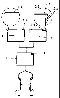
Figure 1 is a plan of the over-mounting of the sheets and the corner cutting
3o thereof.
Figure 2 shows an elevation in section of a container of the invention,
exploded
to show bottom and cover.
Figure 3 is the container, once closed, with details of the finish of the
small
flange overlapping both sheets and of the flanging of the bottom.
3s Figure 4 shows the construction of the circular cover of the preferred

CA 02445252 2003-10-10
3
embodiment, as well as a detail of its finish.
Figure 5 shows its application to the tubular container of laminar origin, of
the
main patent, as well as to a stamped box for holding GDs.
s PREFERRED EIVIBODIIiAENT OF THE INVENTION
In the light of that described above, the present invention relates to a
container
procedure for construction of multi-layer cylindrical containers and
containers so
obtained.
The same belongs to the group of the different containers on the market
to intended for the purpose of conservation and exhibition of individual
products
and, more particularly, to that of drinks of high unit price, although its
application
can extend to other products, including non-alimentary.
This invention is characterized in a special construction of the container,
with
conventional cover and bottom, as well as tubular multi-layer constitution,
the
Is interior in sheet metal and the exterior in cylindrical lenticular
thermoplastic
material.
To this end, one proceeds to cut both sheets in rectangular shapes, one of
them, the interior sheet (1 ), in conventional metallic material, preferably
of the
same type as the cover and the bottom, which can be provided or not with
2o another metallic coating (1.1 ).
While the other sheet (2) is cut slightly smaller in height, the plastic
material is
double with an external layer (2.1 ) which presents an alignment of a
multiplicity
of cylindrical sectors (2.2) which constitute lenses which, depending on the
viewing angle, reflect diverse images incorporated in the innermost plastic
sub
2s sheet (2.3).
One likewise proceeds, simultaneously with each of these sheets (1 ) and (2),
to
the respective cutting of recesses (1.2) and (~.4) of one of their corners,
which
subsequently must be in the upper vertical position. It must also be satisfied
that
this recessing is dimensionally smaller in height in the double sheet (2) of
3o plastic than in the metallic one (1 ).
The two sheets (1 ) and (2) are superimposed, without adhesives and, with
simple appropriate tools, are mutually secured to each other.
Then their end sides are joined and hooked to each other conventionally,
configuring a tube (3) with both sheets, the metallic one and that of plastic.
3s At the top, one proceeds thereafter to configure a flange (1.3), by
rounding off

CA 02445252 2003-10-10
4
the rim of the metallic sheet (1 ), which covers the rim of that of plastic,
so that
one of the ends of the small flange overlaps the other, in the area of the
corner
recess of both sheets.
Thus the plastic sheet (2) is completely embedded, by its upper horizontal
rim,
s inside the small flange (1.3) of the metallic sheet (1 ), except in the
segment of
the recess (2.4), which is flush with the lower rim of the small flange (1.3).
Thus
the overlapping of the flange (1.3) is uniform over the whole mouth of the
tube
(3), by not being superimposed on the bend of the hook of the plastic sheet
(2).
Of the lower vertical side, the lip (1.4) of the metallic sheet, resulting
from the
Io larger cut in the plastic sheet that is abutting against it, is that which
is used for
inserting the stepped (4.1 ) conventional internal bottom piece (4) of the
container.
It is then sufficient to flange (4.2) the bottom to finish the same, introduce
the
product and insert a conventional cover (5).
Is Alternatively, when the body (6) need not have an excessive height it can
be
built by pressing, the same as the cover (7), by mounting previously stamped,
formed and superimposed the plastic sheets (1 ) on the metallic sheet or
sheets
(2), the sheet or sheets (2) leaving a rim (8) projecting beyond the sheets (1
) on
all the periphery thereof, proceeding finally to form a small flange (9)
edging the
2o projecting rim (8) of the metallic sheet or sheets (2) over the rim of the
plastic
layer (1~.
This pressed body (6), in different heights depending on the requirements and
the pressing technique applied, is intended to hold both the aforementioned
CDs and any other product, be this alimentary (cakes, sweets, biscuits,
2s chocolates in compartmented trays, etc.) or garments (underwear,
accessories
and others) or any product of high unit value and capable of being packed.
Both the tube (3) and the equivalent body (6) are prepared with any geometric
configuration of the rim and the skirt: round, oval, polygonal or mixing
straight
segments with other curved ones, as well as having the base thereof both in a
3o flat form and curved concavely or convexly.
The essential nature of this invention is not altered by variations in
materials,
form, size and arrangement of the component elements, described in a non-
restrictive manner, this being sufficient for an expert to proceed to the
reproduction thereof.

Representative Drawing
A single figure which represents the drawing illustrating the invention.
Administrative Status

2024-08-01:As part of the Next Generation Patents (NGP) transition, the Canadian Patents Database (CPD) now contains a more detailed Event History, which replicates the Event Log of our new back-office solution.

Please note that "Inactive:" events refers to events no longer in use in our new back-office solution.

For a clearer understanding of the status of the application/patent presented on this page, the site Disclaimer , as well as the definitions for Patent , Event History , Maintenance Fee  and Payment History  should be consulted.

Event History

Description Date
Time Limit for Reversal Expired 2010-10-12
Inactive: Adhoc Request Documented 2010-07-14
Letter Sent 2009-10-13
Inactive: Office letter 2009-06-01
Revocation of Agent Requirements Determined Compliant 2009-06-01
Revocation of Agent Request 2009-03-31
Grant by Issuance 2007-12-11
Inactive: Cover page published 2007-12-10
Pre-grant 2007-09-25
Inactive: Final fee received 2007-09-25
Notice of Allowance is Issued 2007-05-24
Letter Sent 2007-05-24
Notice of Allowance is Issued 2007-05-24
Inactive: Approved for allowance (AFA) 2007-04-25
Inactive: Office letter 2006-10-30
Inactive: Entity size changed 2006-10-30
Amendment Received - Voluntary Amendment 2006-10-20
Inactive: Corrective payment - s.78.6 Act 2006-10-20
Inactive: S.30(2) Rules - Examiner requisition 2006-04-20
Inactive: IPC from MCD 2006-03-12
Amendment Received - Voluntary Amendment 2005-10-05
Letter Sent 2004-05-31
Application Published (Open to Public Inspection) 2004-05-20
Request for Examination Requirements Determined Compliant 2004-05-20
All Requirements for Examination Determined Compliant 2004-05-20
Request for Examination Received 2004-05-20
Inactive: Cover page published 2004-05-19
Inactive: Inventor deleted 2004-03-15
Inactive: First IPC assigned 2003-12-17
Inactive: IPC assigned 2003-12-17
Inactive: IPC removed 2003-12-17
Inactive: Correspondence - Formalities 2003-12-16
Inactive: Filing certificate - No RFE (English) 2003-11-14
Filing Requirements Determined Compliant 2003-11-14
Application Received - Regular National 2003-11-14

Abandonment History

There is no abandonment history.

Maintenance Fee

The last payment was received on 2007-09-25

Note : If the full payment has not been received on or before the date indicated, a further fee may be required which may be one of the following

  • the reinstatement fee;
  • the late payment fee; or
  • additional fee to reverse deemed expiry.

Please refer to the CIPO Patent Fees web page to see all current fee amounts.

Fee History

Fee Type Anniversary Year Due Date Paid Date
Application fee - small 2003-10-10
Request for examination - small 2004-05-20
MF (application, 2nd anniv.) - small 02 2005-10-10 2005-09-29
MF (application, 3rd anniv.) - standard 03 2006-10-10 2006-10-06
2006-10-20
MF (application, 4th anniv.) - standard 04 2007-10-10 2007-09-25
Final fee - standard 2007-09-25
MF (patent, 5th anniv.) - standard 2008-10-10 2008-08-25
Owners on Record

Note: Records showing the ownership history in alphabetical order.

Current Owners on Record
JOAQUIN DEVESA COMPANY
Past Owners on Record
None
Past Owners that do not appear in the "Owners on Record" listing will appear in other documentation within the application.
Documents

To view selected files, please enter reCAPTCHA code :


To view images, click a link in the Document Description column. To download the documents, select one or more checkboxes in the first column and then click the "Download Selected in PDF format (Zip Archive)" or the "Download Selected as Single PDF" button.

List of published and non-published patent-specific documents on the CPD .

If you have any difficulty accessing content, you can call the Client Service Centre at 1-866-997-1936 or send them an e-mail at CIPO Client Service Centre.


Document
Description 
Date
(yyyy-mm-dd) 
Number of pages   Size of Image (KB) 
Abstract 2003-10-10 1 31
Description 2003-10-10 4 279
Claims 2003-10-10 2 110
Drawings 2003-10-10 4 76
Representative drawing 2003-12-19 1 5
Cover Page 2004-04-23 2 40
Drawings 2006-10-20 4 72
Claims 2006-10-20 2 53
Representative drawing 2007-11-16 1 5
Cover Page 2007-11-16 2 41
Filing Certificate (English) 2003-11-14 1 159
Acknowledgement of Request for Examination 2004-05-31 1 176
Reminder of maintenance fee due 2005-06-13 1 109
Commissioner's Notice - Application Found Allowable 2007-05-24 1 165
Notice: Maintenance Fee Reminder 2009-07-13 1 118
Maintenance Fee Notice 2009-11-24 1 170
Second Notice: Maintenance Fee Reminder 2010-04-15 1 122
Notice: Maintenance Fee Reminder 2010-07-13 1 122
Correspondence 2003-11-14 1 31
Correspondence 2003-12-16 2 60
Fees 2005-09-29 1 27
Correspondence 2006-10-30 1 15
Fees 2006-10-06 2 52
Correspondence 2007-09-25 2 52
Fees 2007-09-25 2 53
Fees 2008-08-25 2 52
Correspondence 2009-03-31 2 46
Correspondence 2009-06-01 1 13
Correspondence 2009-06-01 1 28